Interference Avoidance using Spatial Modulation based Location Aware Beamforming in Cognitive Radio IOT Systems

Adv. Sci. Technol. Eng. Syst. J. 3(2), 49–57 (2018);
 DOI: 10.25046/aj030206
The Internet of Things (IOT) is a revolutionary communication technology which enables numerous heterogeneous objects to be inter-connected. In such a wireless system, interference management between the operating devices is an important challenge. Cognitive Radio (CR) seems to be a promising enabler transmission technology for the 5G-IOT system. The “sense-and-adapt” smart transmission strategy in CR systems can help to overcome the problem of multiple access interference (MAI) in IOT systems. In this paper, a 5G-IOT smart infrastructure system is arranged in the form of CR based virtual antenna array (VAA) system. In VAA based wireless system, knowledge of users’ locations can help the transmitter to achieve interference avoidance by steering the main beam towards the intended recipient. This idea has been applied to the VAA-IOT system, where smart antenna array based location aware beamforming are applied at both transmitter and receiver cluster of smart sensors with the help of spatial modulation principle. The waveform of choice for the CR-IOT clusters is Generalized Frequency Division Multiplexing (GFDM) while corresponding waveform for the primary user (PU) cluster is conventional Orthogonal Frequency Division Multiplexing (OFDM). Computer simulation shows that under multipath fading conditions, the implemented system can reduce the interference to the primary user (PU) system, leading to better coexistence.
1. Introduction
This paper is an extension of work originally presented in 2017 International Conference of Applied System Innovation, held at Sapporo, Japan [1]. In this work, a beamforming scheme is presented which is based on transmitter activation by spatial modulation (SM) technique. Spatial Smoothing (SS) based Multiple Signal Classification (MUSIC) algorithm is applied for direction of arrival (DOA) estimation of the PU. Based on the DOA data, the combined spatial modulation-beamforming scheme is designed for avoiding interference to the PU. In [1], an overview of the methodology was presented. However, in this work, details about application of the SS-MUSIC as well as receiver side data detection are presented. Computer simulations are performed to demonstrate the effectiveness of the designed scheme for better interference avoidance in CR scenario.
Increasing demand for higher data rate and quality of mobile communications has led to the development of advanced multicarrier signaling schemes such as OFDM and GFDM among others. GFDM is a recently proposed non-orthogonal multicarrier waveform which is a potential candidate for 5G wireless technology. Its benefits are flexible carrier aggregation and low out-of-band (OOB) radiation [2-4]. Due to its flexibility in subcarrier allocation, the GFDM based user can sense the spectral bands in a CR environment and intelligently allocate the subcarriers to the bands where the interference temperature threshold can be satisfied. Apart from frequency bands, space and angle dimensions can be exploited too with the recent advances in multiple antenna technologies. In such a smart heterogeneous infra-structure, multi-antenna based GFDM system can lead to enhanced system performance and low cross-tier interference. This can be achieved with the application of beamforming technology at the Femto-Cell transceiver system. Moreover, cognitive radio technology can be combined with beamforming at the Femto-Cell network enabling it to become a self-aware entity [5, 6]. The cognitive Femto-Cell system can use spatial modulation principle to encode the location estimates of the Macro-Cell PUs and select the Femto-Cell users closest to the Femto-Cell SU receiver system. The selected SU transmitters can perform null-steering based beamforming to avoid cross-tier interference by directing nulls towards Macro-Cell PUs. In this work, the CR-IOT [7-9] system is considered as a cognitive Femto-Cell under-laid with an existing main Macro-Cell infrastructure. This kind of cognitive interference management strategy can maximize Femto-Cell CR-IOT system performance while minimizing interference on the Macro-Cell PU system, leading to better spectral coexistence between the primary Macro-Cell user and the secondary Femto-Cell CR-IOT user.
2. System Model
It is assumed that the primary Macro-Cell and secondary Femto-Cell use the same uplink and downlink frequencies and the same bandwidth. The Macro-Cell uses OFDM for transmission, while the Femto-Cell uses GFDM as its signaling scheme. Figure 1 shows the system model.
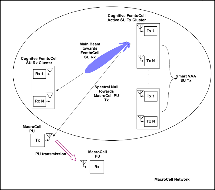 Figure 1. CR-IOT Femto-Cell VAA system under-laid with Macro-Cell PU system
The Femto-Cell based CR-IOT transmitter system is divided into multiple clusters. Each cluster contains a number of low power single antenna terminals arranged in the form of virtual antenna array (VAA) [10, 11]. The VAA based Femto-Cell CR-IOT system collects DOA information about the Macro-Cell PU and performs null-steering based beamforming to transmit its data. It uses spatial modulation principle to encode the DOA information of the PU in the form of bit blocks. This bit-block is used to identify a suitable transmit cluster which is then activated. The terminals in the active SU cluster transmit data to the SU receiver using null-steering based beamforming.
3. Transmitter Side Processing
Let there be ‘Nc’ SU transmitter clusters in total. Let there be ‘N’ terminals within each cluster. A central controller acts as the cluster head. The central controller has the role of the cognitive engine (CE). It is responsible for analyzing the received signal parameters and taking decisions on spectrum band occupancy status and estimated locations of the PUs and SUs. The transmit side processing operation can be divided into 2 phases, namely sensing phase and transmission phase.
- Sensing Phase
The sensing phase operations performed at the SU transmitter side can be pictorially depicted as in Figure 2 below.
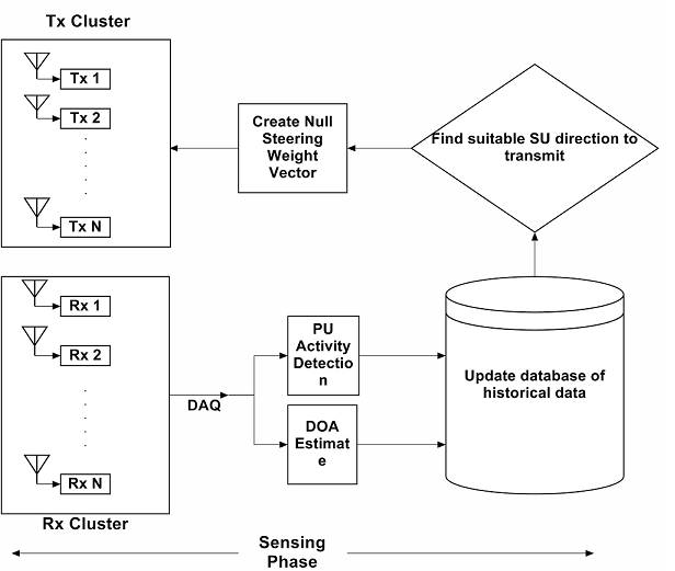 Figure 2. Sensing Phase at the Femto-Cell based CR-IOT transmitter cluster
- PU parameters like Interference Temperature (IT), PU transmission power, available spectrum hole, PU location estimates (for e.g. DOA of received PU signal) etc. are collected and forwarded to the central controller, by the SU clusters.
- Based on received parameters, the central controller calculates the distance of the clusters from the receiver SU. This can be achieved by localization algorithms like angle of arrival (AOA), received signal strength (RSS) estimation etc.
- The central controller maintains a database of possible location estimates of the SU receiver clusters and PU terminals, as well as channel occupancy status within the spectrum band. The DOA estimates are matched with the database entries to verify the presence of PU activity at that location.
Based upon DOA estimation result of the received signal, the central controller creates a null-steering based beamforming weight vector. This is applied to the transmit signal during the transmission phase to steer spectral nulls towards the PU transmitter in order to avoid interference, whereas the main beam is steered towards the SU receiver cluster.
3.2. DOA Estimation by Spatial Smoothing MUSIC
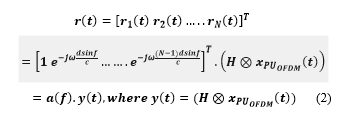
SS-MUSIC [12, 13] is chosen for DOA estimation of the incoming signal under multipath propagation. Let the PU-OFDM signal be denoted by xPU_OFDM(t).
![]() In the above equation, ‘W’ indicates the discrete Fourier transform (DFT) matrix. ‘WH’ indicates the inverse discrete Fourier transform matrix. The term‘s’ indicates the data subcarriers which can be M-ary QAM or M-ary PSK modulated symbols. In general for an antenna array with N terminals, the received signal at all elements of the array can be expressed by the following mathematical equation:
In the above equation, ‘W’ indicates the discrete Fourier transform (DFT) matrix. ‘WH’ indicates the inverse discrete Fourier transform matrix. The term‘s’ indicates the data subcarriers which can be M-ary QAM or M-ary PSK modulated symbols. In general for an antenna array with N terminals, the received signal at all elements of the array can be expressed by the following mathematical equation:
 Suppose the antenna array comprising ‘N’ terminals be divided into ‘L’ overlapping sub-arrays. Each sub-array contains ‘M’ terminals, with M>K, K being the number of source directions. Then, N=M+L-1.
Let xi(t) be the received signal vector at the ith sub-array. Let aM(ф) be the steering vector associated with each sub-array.
![]() With ‘K’ DOAs, the received signal ‘xi(t)’ for the ith sub-array can be expressed by the following mathematical equation:
With ‘K’ DOAs, the received signal ‘xi(t)’ for the ith sub-array can be expressed by the following mathematical equation:
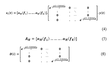
![]() The correlation matrix at each sub-array can be computed as follows:
The correlation matrix at each sub-array can be computed as follows:
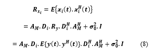 The average of all the correlation matrices at all the sub-arrays can be expressed as follows:
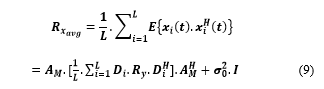 The conventional MUSIC [12] algorithm can be applied on the matrix ‘Rx_avg’ to obtain the DOA estimate of the incoming PU-OFDM signal. The dimension of the matrix ‘AM’ is M-by-M. The dimension of the matrix within square brackets is K-by-K. Hence, it is evident that the dimension of ‘Rx_avg’ is M-by-M.
By calculating the eigen-values of Rx_avg, 2 disjoint eigen-spaces can be identified. One is the signal subspace, and it consists of signal eigen-vectors on which noise is overlapped. The other one is the noise subspace which comprises eigen-vectors only due to noise. The signal eigen-vectors correspond to the ‘K’ (with K≤M-1) greatest eigen-values. The noise eigen-vectors correspond to the other (M-K) eigen-values. The MUSIC algorithm then searches for those steering vectors which are orthonormal to the noise subspace.
Let ui be the ith eigen-vector of Rx_avg corresponding to the eigen-value σi2.
Step 1: We perform eigen-decomposition of the M-by-M matrix ‘Rx_avg’.
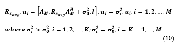 Step 2: The above expression can be re-expressed as follows:
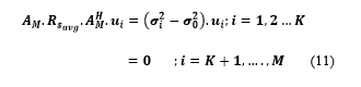 Step 3: We partition the M-dimensional vector space into signal subspace Us and noise subspace Un:
 Step 4: The steering vector associated with the DOA of the PU-OFDM signal is in the signal subspace, the latter being orthogonal to the noise subspace. Hence, the MUSIC algorithm searches through all the angles ‘ф’ and plots the spatial spectrum given by the following equation:
 Whenever the scanned angle ф=фi, the DOA of the PU-OFDM signal, the MUSIC spatial spectrum will exhibit a peak, providing an estimate of the DOA of the PU-OFDM signal.
3.3. Data Transmission Phase
This phase consists of 2 sub-phases, namely VAA cluster index modulated CR-IOT transmit signal generation and null-steering based transmit side beamforming.
i. VAA cluster index modulated CR-IOT transmit signal generation
Multiple-antenna techniques constitute a key technology for modern wireless communications, which trade-off superior error performance and higher data rates for increased system complexity and cost. The basic idea of SM-Beamforming is to map a block of information bits into information carrying units. Each information carrying unit comprises a symbol chosen from a complex constellation diagram and a unique cluster index that is chosen from a set of transmitter clusters. Each transmitter cluster contains a VAA of transmitters arranged in the form of a uniform linear array (ULA). As a consequence, we have a hybrid modulation and MIMO technique [14, 15], in which the modulated signal belongs to a tridimensional constellation diagram [15-17], which jointly combines signal and spatial information (cluster index). At the transmitter side, the bit-stream emitted from the central controller is divided into blocks containing (log2Nc+NM.log2M) bits each, with log2Nc and log2M being the number of bits needed to identify a transmitter cluster and a transmitter symbol from the symbol constellation diagram respectively. Here, ‘NM’ denotes the total number of information symbols to be transmitted for a particular time slot. Each block is then processed by a SM mapper, which splits each of them into two sub-blocks of log2 (Nc) and NM.log2 (M) bits each. The spatial mapper comprises 2 separate tables, namely active cluster index (ACI) mapping table and information symbol mapping table. The ACI mapping table contains a list of the angular locations of the SU transmitter clusters, and bit combinations of size log2 (Nc) corresponding to each transmitter cluster. The incoming bit sub-block of size log2 (Nc) selects that SU transmitter cluster index which is nearest in distance to the SU receiver. It is assumed that the CE already has prior knowledge of the distances based on prior location estimation. The other bit sub-block of size NM.log2 (M) selects NM symbols according to the information symbol mapping table. The ACI mapping table is depicted in Table 1 below:
Table 1. Active Cluster Index (ACI) Mapping Table.
| SU Tx Cluster Index | SU Tx Cluster Locations | Bit Pattern |
| 1 | 30 degrees | 00 |
| 2 | 45 degrees | 01 |
| 3 | 60 degrees | 10 |
| 4 | 75 degrees | 11 |
The information symbol mapping table is shown in Table 2 below:
Table 2. Information Symbol Mapping Table.
| Symbol | Bit Pattern | |
| 1+j | 00 | |
| 1-j | 01 | |
| -1+j | 10 | |
| -1-j | 11 | |
According to the above scheme, only one cluster of SU transmitters is activated at a particular frame instant while the other clusters remain silent. This helps to avoid the inter-cluster interference. In other SM schemes [15-18], only one transmitter antenna is active at a particular time instant, thereby transmitting only one constellation symbol per instant. However in our proposed transmission scheme, multiple information symbols are transmitted by the antenna array leading to improved spectral efficiency.
The cluster index modulated symbol stream is passed through the GFDM modulator, after which null-steering based beamforming is performed by the array of SU terminals within the activated cluster. The process can be pictorially depicted in Figure 3 below:
Details of baseband GFDM transceiver implementation can be obtained from [2].
- Null-Steering Transmit Side Beamforming
The digital baseband signal snapshots x=[x1, x2… xN]T in a transmit beamforming cluster with N single antenna sensors (virtual antenna array) can be represented by the following equation:
![]()
 Figure 3. SM-Beamforming operation in CR-IOT GFDM Transmitter
In the above equation, w(фSU) = [w1(фSU), w2(фSU), ….., wN(фSU)]T represents the beamforming weight vector under a specific optimization criteria towards the desired direction фSU [19],[20]. In other words, фSU is the direction in which the intended SU receiver is located. ‘xSU_GFDM’ refers to the spatially modulated symbol transmitted by the activated SU cluster. It is assumed that the sensors within each transmit cluster are closely spaced. Under this assumption, the effective channels between the different transmit antennas inside the cluster and the receiver antenna differ by phase shift included in the steering vector of the transmit cluster. The steering vector for ULA in direction ‘ф’ can be represented by the following equation [21]:
![]() In the above equation, the constant ‘k’=2π/λ, where λ is the wavelength of the RF signal frequency. The distance between the elements of the cluster is expressed as‘d’. The received snapshot of the signal received at a direction ‘ф’ is represented by the following equation:
In the above equation, the constant ‘k’=2π/λ, where λ is the wavelength of the RF signal frequency. The distance between the elements of the cluster is expressed as‘d’. The received snapshot of the signal received at a direction ‘ф’ is represented by the following equation:
![]() Suppose there is ‘M’ number of PUs operating in the same frequency band as the SU transmitter. Let the angles of the PUs from the SU transmitter be denoted by фPU,1, фPU,2,…., фPU,M. Let the null-steering matrix be denoted by ‘A’. Then the matrix ‘A’ consists of the steering vectors to all the PU directions.
Suppose there is ‘M’ number of PUs operating in the same frequency band as the SU transmitter. Let the angles of the PUs from the SU transmitter be denoted by фPU,1, фPU,2,…., фPU,M. Let the null-steering matrix be denoted by ‘A’. Then the matrix ‘A’ consists of the steering vectors to all the PU directions.
![]() The N-by-N matrix, PA, refers to the orthogonal projection matrix onto the subspace spanned by the columns of A. It is expressed mathematically as follows:
The N-by-N matrix, PA, refers to the orthogonal projection matrix onto the subspace spanned by the columns of A. It is expressed mathematically as follows:
![]() Conventional null-steering beamforming problem can be formulated as follows [19]:
Conventional null-steering beamforming problem can be formulated as follows [19]:
 The solution to the above optimization problem is given as follows [19]:
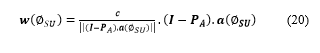
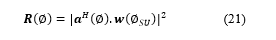
In the above equation, ‘I’ refers to N-by-N identity matrix. The radiation pattern of the activated SU cluster represents the spatial response of the VAA performing the null-steering beamforming with the derived beamforming weights ‘w (фSU)’. Mathematically it can be expressed as follows:
 4. Receiver Side Processing
4.1. Spatial Signature based Matched Filtering
In general, the wireless channel impulse response between the ith terminal in the sth SU transmitter cluster and the jth terminal in the receiver cluster can be represented by the following mathematical equation [22]:
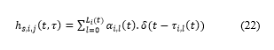 In the above equation, ‘αi,l(t)’ denotes the complex channel amplitude. The number of multipath components is denoted by ‘Li (t)’.The path delay of the lth multipath component is denoted by ‘τi,l(t)’.Let ‘Hs,i,j’ denote the frequency domain channel coefficients between the ith transmitter antenna of the sth SU transmitter cluster and jth receiver antenna.
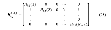
Let ‘Hdiag s,i,j’ denote a diagonal matrix containing the elements of ‘Hs,i,j’ along the main diagonal.
 Let ‘xi SU_GFDM’, i=1, 2…NT , denote the transmitted GFDM signal from the ith transmitter antenna, before application of the null-steering beamforming weight vector. Its mathematical expression is same as that for baseband GFDM signal shown in [2]. Let ‘SiSU_GFDM’, i=1, 2…NT , denote the pre –IFFT GFDM signal as expressed below. As mentioned earlier, details of the mathematical expression for ‘xi SU_GFDM’ can be found in [2].
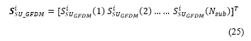
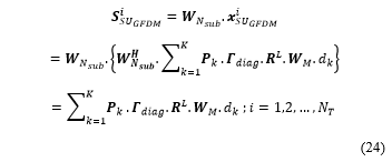 Further, ‘SiSU_GFDM’ can be represented by the column vector as shown below:
 It is assumed that the cyclic prefix (CP) is longer than the maximum delay spread of the channel. So after removal of the CP, the channel appears circular to the symbols. As such, application of FFT converts the circulant channel matrix to diagonal matrix, with frequency domain channel coefficients along the main diagonal.
The null-steering weight vector can be expressed as a column vector as follows:
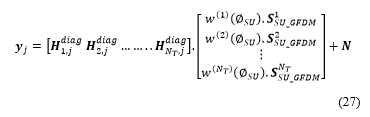
 The received signal at the jth receiver antenna can be expressed as follows:
 The above equation can be re-expressed as:
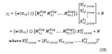 In (28), the sign ‘ʘ’ indicates element-wise multiplication.
Let ‘bj’ denote the spatial signature of the jth receiver antenna.
 Let ‘b’ denote the matrix of spatial signatures at all the receiver antennas.
 Then, the received signal at ‘NR’ receiver antennas can be expressed in terms of the transmitted signal and spatial signature associated with each receiver antenna as follows:
![]() It is assumed that the channel is temporally slowly fading and that each post-FFT sample of the received GFDM signal encounters independent and identical Rayleigh distribution. Moreover, the channel stays constant over a number of symbols and the receiver has perfect knowledge of the slowly varying channel. The receiver computes the pseudo-inverse of the spatial signature matrix ‘b’ to recover the transmitted spatially modulated GFDM signal.
It is assumed that the channel is temporally slowly fading and that each post-FFT sample of the received GFDM signal encounters independent and identical Rayleigh distribution. Moreover, the channel stays constant over a number of symbols and the receiver has perfect knowledge of the slowly varying channel. The receiver computes the pseudo-inverse of the spatial signature matrix ‘b’ to recover the transmitted spatially modulated GFDM signal.
4.2. Active Transmitter Cluster Index Estimation
While it is assumed that the receiver has perfect knowledge of the spatial signatures, the receiver does not have knowledge which transmitter cluster is active for that particular frame instant. The receiver performs spatial signature based matched filtering on the received signal using spatial signature belonging to each SU transmitter cluster and stores the result in vector form in a buffer. Next, the receiver computes the squared absolute value of each stored vector in the buffer and compares the result to find out the maximum value. The index of the maximum value gives an estimate of the active transmitter SU cluster.
The procedure is tabulated in Table 3 below:
Table 3. Spatial Signature based Matched filtering
|
5. Simulation Results and Analysis
In this section, simulation results are provided to evaluate the performance of the proposed system under multipath Rayleigh fading channel environment. It is assumed that the clusters are closely spaced. Inter-element distance within each cluster is d=0.5λ, where ‘λ’ is the wavelength. Cluster elements are arranged in the form of ULA. The center frequency of operation of both the CR-IOT Femto-Cell and primary Macro-Cell is fc=2.3 GHz. The number of transmitter and receiver terminals within each cluster in the CR-IOT Femto-Cell network is 16. The multicarrier signaling scheme chosen for the Femto-Cell CR-IOT system is GFDM, which uses M-ary QAM constellation. The Macro-Cell PU system uses OFDM waveform, which also uses M-ary QAM constellation. The PU-OFDM transmitter is assumed to be at 45 degrees.
The following table shows the specifications of the Femto-Cell CR-IOT GFDM waveform.
Table 4. GFDM system parameters
| Simulation Parameters for SM-beamformer GFDM system | |
| Total number of time slots 5
|
|
| Active Subcarrier Indices 100:200 | |
| Pulse Shaping Filter RRC | |
| RRC Overlap Factor 0.1 | |
| Number of SU Tx clusters 4 | |
| Number of SU Tx terminals per cluster 16 | |
| Number of SU Rx clusters 1 | |
| Number of SU Rx terminals per cluster 16 |
In Figure 4 showing antenna array pattern, null is steered at 45 degrees which is the Macro-Cell PU-OFDM transmitter’s location. The SS-MUSIC algorithm provides the DOA estimate of the PU-OFDM transmitter, which helps to steer null towards the PU location. As evident from Figure 4, the red dotted line at 45 degrees indicates the direction of the Macro-Cell PU-OFDM transmitter.
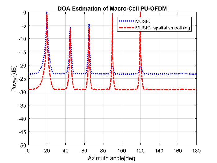 Figure 4. Cognitive Null Steering towards Macro-Cell PU-OFDM user
SS-MUSIC is preferred over conventional MUSIC primarily because of the fact that under multipath propagation, the latter does not perform well in identifying all the sources. This is because under multipath propagation environment, 2 or more DOAs might belong to the same source .i.e. for ‘K’ number of DOAs, actually the number of sources might be less than ‘K’ under multipath environment.
Figure 5 shows DOA estimation performance comparison between SS-MUSIC and conventional MUSIC for 2 sources arriving at the receiver from different directions, under multipath propagation conditions.
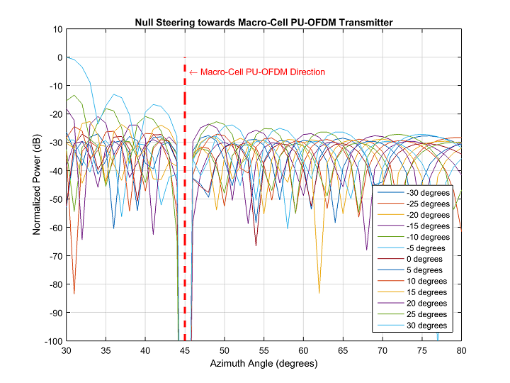 Figure 5. SS-MUSIC vs conventional MUSIC
As evident from Figure 5, for signals with multipath components too close to the main direction, the estimation capability of SS-MUSIC is better due to the application of the smoothing procedure. In the above figure, resolution of the main DOA (45o) and the multipath DOAs (20o, 65o, 90o and 120o) by the SS-MUSIC is better than that with MUSIC.
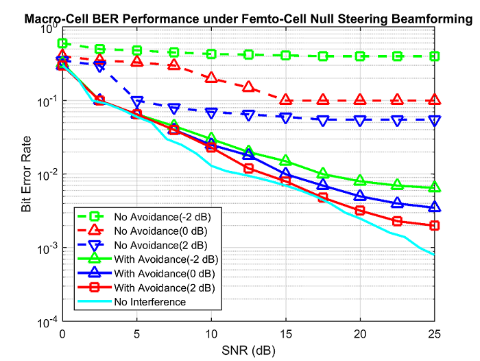 Figure 6. BER performance of Macro-Cell based PU-OFDM
Figure 6 compares the BER curves as a function of SNR for different signal-to-interference ratio (SIR) values for the Macro-Cell PU-OFDM user under conditions of no interference avoidance and with interference avoidance. As evident from the above figure, the Macro-Cell PU suffers significant performance loss under no interference avoidance scenario; however considerable performance improvement is achieved with the application of the cognitive null-steering based beamforming at the Femto-Cell CR-IOT GFDM transmitter.
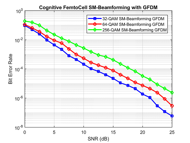 Figure 7. BER performance of Femto-Cell based CR-IOT GFDM
The proposed SM-beamforming system is very well capable of avoiding interference to the PU system for signal-to-noise ratio (SNR) less than or equal to 15 dB. At higher SNR values, it is observed that there is presence of residual interference. This happens due to imperfect steering of nulls at higher SNRs, for different SIR values.
Figure 7 shows the BER performance of the Femto-Cell based CR-IOT GFDM employing SM-beamforming scheme. As expected, BER for 256-QAM system is higher than that of 32-QAM and 64-QAM system under multipath Rayleigh fading channel conditions.
6. Conclusion
This paper introduces the application of SM based null-steering beamforming in VAA based CR-IOT system, under multipath fading channel conditions. Computer simulation results show that the proposed scheme can lead to good BER performance of the PU system by appropriate design of the null-steering beam-former. Moreover, the application of beamforming at the spatial modulation based SU transmitter also provides good BER performance of the SU system under multipath channel conditions. Spatial Smoothing based MUSIC is selected for DOA estimation due to its superiority over conventional MUSIC under multipath propagation. However, performance analysis of other DOA estimation algorithms needs to be evaluated for multicarrier signaling case. As a future work, transmit-receive beamforming schemes with DOA estimation will be investigated under full duplex spatial modulation based transmission conditions.
Conflict of Interest
The authors declare no conflict of interest.
Acknowledgment
This work was supported by National Taipei University of Technology, Taiwan.
- Datta, H.P. Lin, D.B.Lin, “Spatial modulation based location aware beam-forming in GFDM modulated cognitive radio systems”, in International Conference on Applied System Innovation, Sapporo Japan, 2017. https://doi.org/ 10.1109/ICASI.2017.7988357
- Gaspar, N. Michailow, A. Navarro, E. Ohlmer, S. Krone, G. Fettweis, “Low Complexity GFDM Receiver Based on Sparse Frequency Domain Processing” in Proceedings of the IEEE 77th Vehicular Technology Conference, Dresden Germany, 2013. https://doi.org/ 10.1109/VTCSpring.2013.6692619
- Michailow, M. Matthé, I.S. Gaspar, A. Navarro, L.L. Mendes, A. Festag, “Generalized Frequency Division Multiplexing for 5th Generation Cellular Networks” IEEE Trans. Comm.., 62(9), 3045-3061, 2014. https://doi.org/10.1109/TCOMM.2014.2345566
- Michailow, I. Gaspar, S. Krone, M. Lentmaier, G. Fettweis, “Generalized frequency division multiplexing: Analysis of an alternative multi-carrier technique for next generation cellular systems” in Proceedings of the IEEE International Symposium on Wireless Communication Systems, Paris France, 2012. https://doi.org/ 10.1109/ISWCS.2012.6328352
- Gur, S. Bayhan, F. Alagoz, “Cognitive femtocell networks: an overlay architecture for localized dynamic spectrum access.” IEEE Mag. Wireless Comm, 17(4), 62-70, 2010. https://doi.org/ 10.1109/MWC.2010.5547923
- Z. Shakir, R. Atat, M.S. Alouini, “On the interference suppression capabilities of cognitive enabled femtocellular networks”, Proceedings of the IEEE International Conference on Communications and Information Technology, Hammamet Tunisia, 2012. https://doi.org/ 10.1109/ICCITechnol.2012.6285835
- Rawat, K.D. Singh, J.M. Bonnin, “Cognitive radio for M2M and Internet of Things: A survey”, Comp Comm., 94, 1-29, 2016. https://doi.org/10.1016/j.comcom.2016.07.012
- Katzis, H. Ahmadi, “Challenges Implementing Internet of Things (IoT) Using Cognitive Radio Capabilities in 5G Mobile Networks”, Internet of Things (IoT) in 5G Mobile Technologies, 8, 55-76, 2016.
- Fantacci, D. Marabissi, “Cognitive Spectrum Sharing: An Enabling Wireless Communication Technology for a Wide Use of Smart Systems”, Future Internet, 8, 23, 2016. https:// doi:10.3390/fi8020023
- Dohler, E. Lefranc, H. Aghvami, “Space-time block codes for virtual antenna arrays”, Proceedings of the IEEE International Symposium on Personal, Indoor and Mobile Radio Communications (PIMRC), Lisboa, Portugal, 2002. https://doi.org/ 10.1109/PIMRC.2002.1046733
- Dohler, E. Lefranc, H. Aghvami, “Link capacity analysis for virtual antenna arrays”, Proceedings of the IEEE 56th Vehicular Technology Conference, Vancouver, Canada, 2002. https://doi.org/ 10.1109/VETECF.2002.1040381
- D. Rao, K.V.S. Hari, “MUSIC and spatial smoothing: A statistical performance analysis”, Proceedings of the Twenty-Third Asilomar Conference on Signals, Systems and Computers, Pacific Grove, USA, 1989. https://doi.org/ 10.1109/ACSSC.1989.1201035
- Paulraj, V.U. Reddy, T.J. Shan, T. Kailath, “Performance Analysis of the Music Algorithm with Spatial Smoothing in the Presence of Coherent Sources”, Proceedings of the IEEE Military Communications Conference, Monterey, USA, 1986. https://doi.org/ 10.1109/MILCOM.1986.4805849
- R, Schmidt, “Multiple emitter location and signal parameter estimation”, IEEE Trans. Antennas and Propagation, 34 (3), 276-280, 1986. 1109/TAP.1986.1143830
- D. Renzo, H. Haas, P.M. Grant, “Spatial modulation for multiple-antenna wireless systems: a survey”, IEEE Communications Mag., 49 (12), 182-191, 2011. https://doi.org/10.1109/MCOM.2011.6094024
- D. Renzo, H. Haas, A. Ghrayeb, S. Sugiura, L. Hanzo, “Spatial Modulation for Generalized MIMO: Challenges, Opportunities, and Implementation”, Proceedings of the IEEE, 102 (1), 56-103, 2014. https://doi.org/ 10.1109/JPROC.2013.2287851
- Mesleh, H. Haas, C.W. Ahn, S. Yun, “Spatial Modulation-A low Complexity Spectral Efficiency Enhancing Technique”, in Proceedings of First International Conference on Communications and Networking in China, Beijing, China, 2006. https://doi.org/ 10.1109/CHINACOM.2006.344658
- Jeganathan, A. Ghrayeb, L. Szczecinski, “Spatial Modulation: Optimal Detection and Performance Analysis”, IEEE Communications Letters, 12(8), 545-547, 2008. https://doi.org/ 10.1109/LCOMM.2008.080739
- Zarifi, S. Affes, A. Ghrayeb, “Collaborative Null-Steering Beamforming for Uniformly Distributed Wireless Sensor Networks”, IEEE Trans. Signal Process. 58 (3), 1889-1903, 2010. https://doi.org/ 10.1109/TSP.2009.2036476
- Friedlander, B. Porat, “Performance analysis of a null-steering algorithm based on direction-of-arrival estimation”, IEEE Trans. Acoust., Speech, Signal Process. 37 (4), 461 –466, 1989. https://doi.org/ 10.1109/29.17526
- Godara, “Application of antenna arrays to mobile communications. II. beam-forming and direction-of-arrival considerations”, Proc. IEEE 85 (8), 1195 –1245, 1997. https://doi.org/ 10.1109/5.622504
- B. Ertel, P. Cardieri, K.W. Sowerby, T.S. Rappaport, J.H. Reed, “ Overview of spatial channel models for antenna array communication systems”, IEEE Pers. Comm., 5 (1), 10-22, 1998. https://doi.org/ 10.1109/98.656151