Modelling and Simulation of Reduce Harmonic Distortion in Non-linear Loads

Adv. Sci. Technol. Eng. Syst. J. 5(5), 364–369 (2020);
 DOI: 10.25046/aj050545
Harmonic distortion is a problem that can be caused by the use of power electronic devices. The effect of harmonics has an impact on changes in the input voltage source waveform which is referred to as wave defects. This incident has an impact on electronic faults and overheating of the power transformer coil as a supplier. One cause of the emergence of harmonics is the use of non-linear loads on the electric power system. Utilization of non-linear loads such as arc fires (metal casting), welding, magnetic core in transformers and rotating machines, synchronous machines, adjustable speed drives, solid-state switches High voltage DC transmission and Photovoltaic invertors can produce input wave defects. The filter is modelled through a reference current which is used as a PWM pulse generator reference signal to trigger the inverter, further generating a filter current that is injected into the system. Inverter control uses the Propositional Integrator (PI) control approach. From the simulation test results using the Psim software, it is shown that the recorded input waves due to harmonic distortion can be corrected by placing an active filter into the power system.
1. Introduction
Modeling and simulation have been widely applied in the field of electric power systems, through modeling and simulation, being able to observe and analyze system performance like the actual system, this is done by simulation [1]. The use of various power electronic equipment such as power converters and other non-linear loads in the industry and by consumers at this time has an impact on an increase in damage to the electrical system voltage and distorted waveforms called harmonics. The presence of harmonics in the power grid results in greater power losses in distribution, disruptions in communication systems and the chance of failure of the operation of electronic equipment that has high sensitivity, including microelectronic control systems. Power quality problems that occur in consumers due to harmonics are a serious concern [2]. Power quality problems that occur to consumers due to harmonics are a serious concern. International standards on electric power quality (IEEE-519, IEC 61000, EN 50160) insist that electrical equipment and facilities should not produce harmonic content greater than the value specified, and
also sets a distortion limit to the supply voltage. So that efforts to control harmonics can be done one of them by using active filters [3-5].
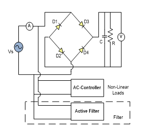
Figure 1: Non-Linear Loads System using Active Filter
Figure 1 shows a non-linear load consisting of a single-phase AC to DC converter with a C filter and a controlled AC load, which are two non-linear loads that cause harmonic generation. An active filter injects current output which will reduce harmonics due to the two non-linear loads. Problems from non-sinusoidal currents due to non-linear loads. The pulsed current has been discussed (corrected) using the “hight power factor pre-regulator” with an uncontrolled rectifier load with a boost converter, this has been discussed in [2]. Application of use for this system if used on a heater can change the system output (output). The processing power demand of a very large pre-regulator with AC control produces harmonics.
Harmonics are a series of current or voltage waves whose frequency is an integer multiple of the base frequency of the voltage or current itself [9]. The integer multiplier at the frequency of the harmonics is the order of n of the harmonics. For example, the basic frequency of an electrical system in Indonesia is 50 Hz, so the second harmonics are 2 x 50 Hz (100 Hz), the third is 3 x 50 Hz (150 Hz), and so on until the nth harmonics that have n x 50 Hz frequencies. Wave defects caused by interactions between the system’s sinusoidal waveforms and other wave components are better known as harmonics, which are other wave components that have integer multiples frequencies from their fundamental components.
2. Inverter and Control Equivalent Models
A Circuit-equivalent Models for Current-controlled Inverters are used as a control circuit for Models for Three-Phase Inverters [10]. however, in this design, Single-phase inverters are used as active filters to reduce harmonics. Use of a single-phase full-bridge inverter as an active filter. The use of Fuzzy control has been recommended to minimize harmonics in single-phase inverters. In a conventional PWM inverter, a gate signal for the switching element in the first leg will be generated compared to a sinusoidal modulation signal via a triangle carrier wave. A phase shift signal of 180 ° from the first foot is applied to the second leg of the inverter. The gate signals for switches S1, S4 and S2, S3 are synchronized respectively [11]. Figure 2 shows the inverter used as an active filter.
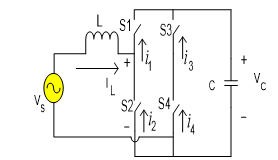
Figure 2: Single-Phase Inverters are Used as Active Filters
Figure 2 shows the active filter scheme, assuming that Vc > ôVsô. During the positive half-wave source voltage, iL The value can be set to a positive value by making Vx = 0; IL can be set near zero by making Vx = Vc, During the half-wave negative.
source voltage, iL will be negative by making Vx=0; iL can be set to zero by making Vx = -Vc. Specifically switches S3 and S4 can be used to strengthen Vx £ 0 and Vx ³ 0, respectively, while switches S1 and S2 are used to activate IL.
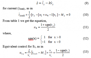
For modelling and control, assume the state of each inverter switch is.
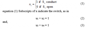
A definition of u for other switches will be obtained, Vx = [u1 u4 – u2 u3]Vc. Or, using an equation Vx = [u1 + u4 – 1] Vc, and ic = [u1 + u4 – 1] iL. With the above analysis, the equation for the inductor current and the capacitor voltage is obtained
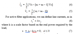
where k is a scale factor based on the real power required by the load,
s = is – k.vs = 0; (7)
From equation (7) we can control to control . Filters can make positive or negative according to switch operation. Besides, the accuracy of this design ensures ½ ½>½k ½. From equation (7) we can control to control. Filters can make positive or negativity according to switch operation. Besides, the accuracy of this design ensures ½ ½>½k ½. for the u1 value under the condition the filter control constant used is 0. Whereas for the u1 value under the condition the filter control constant used is 1. for the u3 value under the condition the filter control constant used is 0. whereas for the u1 value under the condition the filter control constant used is 1. The active filter control value setting for a non-linear load is shown in table 1.
Table 1: The Nonlinear Control Setting Used
in the Application of an Active Filter
| Control setting | ||
| u1 | 0 | 1 |
| u2 | 1 | 0 |
| u3 | 1 | 0 |
| u4 | 0 | 1 |
3. Concept of Equivalent Control and Control design for Active Filters.
The concept of equivalent control is based on shift control. From Kirchhoff’s law, the current at the source will be obtained,
![]()
where I load is a combination of current from a nonlinear load, then,
Active filter circuit design based on Figure 2, then we can take the equation:
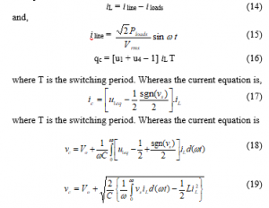
The inductance value of filter L is determined by equation (19). With u1eq it is running from u1. In this equation, the determination of the limit u1 is 0 £ u1eq £ 1. The PI control will be used to adjust the capacitor current. Changes in current capacitors will be related to changes in the magnitude of the line current and changes in the average power caused by nonlinear loads. Capacitor current is connected to the low-pass filter which produces an average capacitor current. will be compared between the nominal capacitor current and the difference from the PI control. The PI control output, the comparison factor, k, is used to control the reference for the line current.
4. Simulation of a Non-linear Loads without Active Filter and using Active Filter
4.1. Non-linear Load Simulation without Active Filter
Figure 1 is used as a basis for simulating the use of active filters in non-linear loads, the system can be simulated with the Psim program. Where here will be compared the results of system simulations without using an active filter with a system that uses an active filter. The parameter values used in this simulation can be seen in table 2.
Table 2: Data for Simulation Tests
| Name | Symbol | Value |
| AC Controller | R | 30 W |
| Uncontrolled Rectifier | C | 1250 mF |
| R | 33 W | |
| Aktif Filter | L
C |
1.75 mH
1280 mF |
Based on the parameters above, the system in the simulation with the Psim program can be seen in figure 3, where the system with two nonlinear loads without using an active filter.
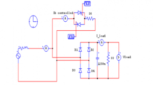
Figure 3: Simulation Non-Linear Loads without Active Filters
Figure 3, shows an electric circuit with multi-non-linear loads. The image is a reference in simulating the effect of non-linear loads. The circuit image consists of a single-phase rectifier with a C filter. On the other hand, a controlled AC load is also installed as assuming a non-linear multi-load. Input voltage 220 Volt with a frequency of 50 Hz as a source to supply non-linear load needs. A simulation device for measuring the input current waveform is mounted on the input and output loads. To see the effect of non-linear load performance. A single-phase rectifier uses a capacitor filter in parallel with another load that is a controlled AC load. Each load is connected to an AC voltage source of 220 V, 50 Hz. The simulation uses Psim software, with the simulation results shown in figure 4 a-d.
Figure 4.a shows the output waveform of a controlled rectifier as a non-linear load. Rectifier that converts an AC source to DC for a specific load requirement.
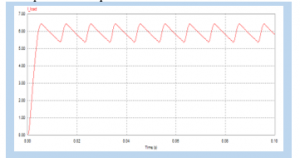
Figure 4.a: Load Current in Single-Phase Rectifier
The effect of ripple reduction in a rectifier using the C input filter causes the input current source to become distorted, as shown in figure 4.b
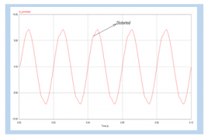
Figure 4.b: Input current at controlled AC load
The input current at a non-liner load without using a filter indicates that the input waveform has been distorted, such as the simulated display shown in figure 4.c
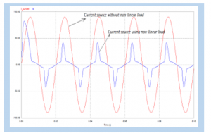
Figure 4.c: Current Source Using Non-Linear Loads and
Current Source without Non-Linear Loads.

Figure 4.d: Harmonic Spectrum- FFT Input Current of Non-Linear Loads
without Active Filters
Figure 4.a is the output of a single-phase wave rectifier with filter C. Filter C is intended to reduce the ripple in the need for a direct current source, generated by the rectifier. Figure 4.b is a display of input waves from a controlled AC load. From the picture, it can be seen that the waveform is not sine (distorted) this is due to the effect of the controlled AC load, Whereas Figure 4.c. shows the comparison of the source current when not yet burdened by non-linear loads, and after being burdened by non-linear loads. From the image display, there is a distortion in the source current wave. This is caused by the influence of two non-linear loads attached to the circuit. Furthermore, to see the amount of distortion caused by harmonics, the harmonic spectrum in Figure 4.d shows the suitability of the harmonics in the source current [12]. wave form the current in each phase is not pure sinusoidal, meaning that the system current has been distorted by harmonics due to non-linear loads. The simulation results for the current harmonic spectrum in Figure 4.d can be seen the THD Harmonics value as in Table 3.
Table 3. Harmonics Input Currents Without Active Filters
| Harmonic components | Freq.
(Hz) |
Current (IS) |
| Fundamental currents | 50 | 19.0 |
| 3rd Harmonics (I3) | 150 | 6.78 |
| 5rd Harmonics (I5) | 250 | 5.65 |
| 7rd Harmonics (I7) | 350 | 4.02 |
| The 9rd Harmonics (I9) | 550 | 1.51 |
| Total Harmonic Distortion (THD) % | 51.65 | |
The harmonic distortion value in the harmonic spectrum simulated in Figure 4.d is 51.65%, while according to the IEEE 519-1992 standard it has been set that the allowable THD limit is 15%. From the calculation results, total harmonic distortion (THD) in table 3 has exceeded the standard. Harmonic improvement due to non-linear loads is carried out by installing active filters, to observe the effect of active filters in reducing harmonic distortion.
4.2. Simulation of a Nonlinear Loads using Active Filter
The filter design to reduce harmonics in this simulation uses active filters that are controlled using PI controls. The active filter is a new type of harmonic elimination filter device in the power system. This filter is composed of power electronic devices. The main components contained in the active filter area. Inverter The inverter is used as an active filter that is connected in parallel with the load voltage source to compensate for the harmonics. Controller The controller is used in an active filter circuit to reduce the error signal at the load voltage source. The non-linear load simulation design mounted on the active fist is shown in Figure 5.
The working principle of the shunt active filter is to compensate for the load current in a simple way, namely injecting harmonic currents whose phase is 1800 different from that of the load generated, thereby eliminating each other. The active filter gets the input from the source voltage and load current which is used to obtain the harmonic reference current in the control system. Theory reactive active power (p-q) is used as a control to get reference current. The reference current will be used to reference the PWM generator which will be compared with the carrier signal which will generate pulses. The pulse is used to trigger the inverter which is then used to generate a filter current wave for injection. Use of VSI (Voltage Source Inverter) to allow the adjustment of harmonic currents in the active filter. This inverter uses a dc capacitor as supply and can perform a switching process at high frequencies to produce a signal that is able to overcome the harmonic currents generated by non-linear loads. Proportional integral control (PI) with the input signal in the proportional integral control with a filter amplifier (LP) is the difference between the harmonic signal from the band pass filter, the inverter output signal is negative feedback, this PI control is used in the Voltage Source Inverter control as an active filter.
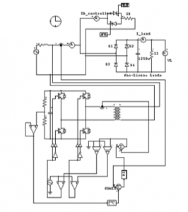
Figure 5: Simulation Circuit of Non-Linear Load using Active Filter

Figure 6. a: Source Current Waveform using Active Filter
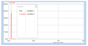
Figure 6.b: Harmonic Spectrum-FFT Input Voltage
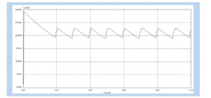
Figure 6.c: Load Current Waveforms
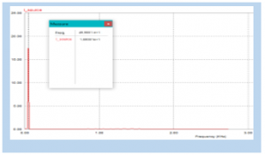
Figure 6.d: Harmonic Spectrum-FFT Input Current
Figure 5, shows a simulation of a non-linear load mounted on an active filter. Observation of simulation performance through the effect of filter installation on the input current. Without an active filter, it can be seen that there are harmonics in the input current due to the non-linear load. After installing the active filter, the simulation results are shown in Figure 6 (a-d).
Figure 6 a-d shows the simulation results of each non-linear load using an active filter. The response plot from the simulation results shows that wave defects in the input current arising from non-linear harmonic loads can be reduced using active filters using PI control.Figure 6.1 is a form of input current using an active filter with a DC voltage output from the load rectifier shown in Figure 6.c.
Figures 6.c and 6d show the harmonic spectrum for input voltage and input current using active filters, respectively. It can be seen from the observation that harmonics can be reduced using an active filter, so that the FFT of the spectrum in Figures 6.c and 6.d is only the fundamental voltage and current at the fundamental frequency of 50 Hz, shown in table 4.
Table 4. Harmonics Input Currents and Voltage Using Active Filters
| Harmonic components | Freq.
(Hz) |
Current (IS) |
| Fundamental current | 49.9801 | 18.93 |
| Fundamental Voltage | 50.82 | 219.03 |
From these results it can be seen that the difference in harmonic improvement without using an active filter (table 3) and by using an active filter (table 4). From the two comparisons, the results show that the use of an active filter can improve the input current wave defects (system harmonics), based on the IEEE 519-1992 standard, the harmonics are less than 5%.
5. Results and Discussion
From the circuit simulation in Figure 3 with an unfiltered system and Figure 6. which illustrates the system using an active filter, the following results will be shown: When a single-phase source is connected to a multi-linear non-load system, the controlled rectifier and AC load driver causes the input side, the current to be distorted and contain harmonics as shown in Figures 4.b and 4c. The FFT of the input current containing harmonics is shown in Figure 4.d. showing non-sinusoidal current waves. Input currents have pulsating (wave vibrations) if the system is maintained with non-sinusoidal conditions that will affect the system’s work and can damage the equipment. (heating of the winding and transformer core). The non-linear multi-load system is connected in parallel with a single-phase active filter as shown in figure (5). To keep producing a DC output like Figure 6.c, the rectifier is given a filter capacitor, as a result, a wave defect will occur. This wave defect is corrected with an active filter so that the current at the input side will return sinusoidal as shown in Figure 6.a. Simulation results for multi-load non-linear with active filter show the waveform on the input side (Source Side) again does not experience waveforms (distorted) spectrum harmonics (FFT) seen in Figure 6.b only fundamental harmonics only, this shows that the use of active filters reduces harmonics and corrects input current waveform defects.
6. Conclusion
Non-linear load simulation without active filter and using an active filter with PI control, it can be concluded:
- Non-linear load distorts the input current. The harmonics content in the input current through the FFT plot graph shows the harmonics 3, 5, 7 dan 9 have significant values.
- PI control system inputted on the inverter circuit as an active filter has a good function in reducing harmonics. The simulation results show that the input current FFT after using an active filter is only the fundamental current. This shows that harmonics have improved with the installation of an active filter.
Conflict of Interest
The authors declare that there is no conflict of interests regarding the publication of this paper.
Acknowledgement.
This research did not receive any specific grant from funding agencies in the public, commercial, or not-for-profit sectors. This paper was produced from the results of research activities supported by LPPM UNIMED
- A. Rahmaniar, Junaidi, Ganefri, A.Hamid K, N.Jalinus, J.Jama, “ Modelling and Simulation: An Injection Model Approach to Controlling Dynamic Stability Based on Unified Power Flow Controller,” Journal of Theoretical and Applied Information Technology, 97(20), 2334-2345, 2019.
- M. Halpin, W.Xu, S Ranade, P.F. Ribeiro.”Tutorial on Harmonics Modeling and Simulation”, IEEE Power Engineering Society Harmonics Working Group, 1998
- F. Z. Peng, George W.O. Jr, D.J. Adams, “Harmonic and Reactive Power Compensation Based on the Generalized Instantaneous Reactive Power Theory for Three-Phase Four-Wire Systems,” IEEE Transactions On Power Electronics, 13(1), 1998. DOI: 10.1109/63.728344
- M. Rafiei, H. Toliyat, R.G. T. Gopalarathnam, “An Optimal and Flexible Control Strategy for Active Filtering and Power Factor Correction Under Non-Sinusoidal Line Voltages”, IEEE Transactions On Power Electronics, 13(16), 2001, DOI: 10.1109/61.915499
- K. Hemachandran, B.Justus, S.S. Darly, “Harmonic Mitigation In A Single Phase Non-Linear Load Using SAPF With PI Controller” Recent Advances in Electrical Engineering and Computer Science, 157-161, 2015, Doi: 10.13140/RG.2.1.2897.7365.
- Faiz J, Shahgholian G,” Modeling And Simulation Of A Three-Phase Inverter With Rectifier-Type Nonlinear Loads”, Armenian Journal of Physics, 2(4), 307-316, 2009.
- J.R. Johnson, “Managing harmonics and resonance with active harmonic filters in an offshore ring main oil field,” in 13th International Conference on Harmonics and Quality of Power, 2008, DOI: 10.1109/ICHQP.2008.4668749
- S.M. Adnaan, “ Design And Simulation Of A Nonlinear Load Model Used to Simulate Voltage Notches And Harmonics Caused By A 6-Pulse Three-Phase Rectifier,” International Journal of Science, Engineering and Technology Research, Volume 06(06), 984-995, 2017.
- E.H Mayoral, M. A. H López, E.R Hernandez, H.J.C. Marrero, J.R.D Portela, V.I.M Oliva, ” Fourier Analysis for Harmonic Signals in Electrical Power Systems”, InTech, 2017.
- B. Johnson, Minghui Lu, V.Purba, S.Dhople, “Circuit-equivalent Models for Current-controlled Inverters”, IEEE, 2019, DOI: 10.1109/COMPEL.2019.8769670
- D. A. Torrey, A.M.A.Zamel, “Single-Phase Active Power Filters for Multiple Non-Linear Loads,” IEEE Transactions on Power Electronics, 10 (3), 1995, DOI: 10.1109/63.387990.
- D. Shmilovitz, “On the Definition of Total Harmonic Distortion and Its Effect on Measurement Interpretation,” IEEE Transactions On Power Delivery, 20(1), 2005, DOI: 10.1109/TPWRD.2004.839744.