Open Energy Distribution System-Based on Photo-voltaic with Interconnected- Modified DC-Nanogrids
 , Nourhan Ahmed Maged 1, Naser Abdel-Rahim 2, Fahmy Bendary 3
Adv. Sci. Technol. Eng. Syst. J. 6(1), 982–988 (2021);
 DOI: 10.25046/aj0601108
This manuscript exhibits a perfect design for a flexible number of modified DC nanogrids within an open energy distribution network (OEDN) that interconnected via a DC bus. Each modified nanogrid implies a single-input multi-output switched boost inverter (SIMO-SBI). The DC-output for each inverter is robustly controlled to keep the DC-bus interconnected voltage constant. The proposed control uses model reference technique to defeat the non-linearity of the system. In addition, a control algorithm is proposed to manage the optimum power flow and increase the system reliability. The MATLAB/Simulink program is used in modelling and simulation of the suggested arrangement to achieve the robustness of the proposed OEDN with multiple 5-Kw interconnected nanogrids fed from photovoltaic (PV) arrays. Several simulation results are introduced for both open and closed loop control to verify the robustness and validity of the system against the main parameters’ changes. In accession, the smoothing power flow between nanogrids indicates that the proposed algorithm for the controller is sophisticated and able to supervise the power among all nanogrids of an OEDN.
1. Introduction
AC generation, distribution and transmission for long distances had been in existence for even more than a century with the high spread for the AC loads in the markets [1].
Conventional AC grid depends mainly on traditional energy sources – such as oil, coal and natural gas – that are permeable and polluting the environment. Also, this classical grid uses a centralized control system that is sensitive to any fault occurrence and cause an outage for the whole network such as New York blackout in Aug. 2003. So, decentralized control techniques are good solutions for this traditional network [2].
Renewable energies such as solar, wind, geothermal, biomass are environmental friendly distributed generation (DG) resources. Most of these renewable resources such as photovoltaic systems and fuel cells produce a DC output power that can directly feed to the DC loads without AC conversion. Unfortunately, the generated power from those renewable resources is limited and intermittent. These small-rated resources can be classified according to its rating capacity as: mini grid rate from 50 kW to 1.5 MW, micro grid rate from 5 kW to 50 kW, nano grid rate from 1.5 kW to 5.0 kW, and the smallest one is a pico grid rate less than 1.5 kW [3].
These compact DC grids can be interconnected with each other via a simple-configuration DC bus instead of AC interconnections. DC-interconnection don’t need to synchronization, quickly integrated with distributed generation (DG), and no skin effect for transmission lines [4].
Classical DC nano-grid has large numbers of two-stage converter-inverter set. The interconnection of this combined set causing some problems such as communication interference with noise. In addition, the main disadvantage of the two-stage converter-inverter set is that it needs to be protected against overlapping of the two inverter-switches on the same arm [5].
The authors in [6-8] described a new modified model for the DC nanogrid with the help of single-input multi-output switched boost inverter (SIMO-SBI). It improves the system efficiency and increase its reliability. In addition, it produces simultaneously DC and AC voltages in a single stage.
In [9], the authors presented a complete analysis for SBI, control circuits, and open-loop control strategy fed from photovoltaic (PV) generator was proposed. Also, in [10], The authors proposed a closed-loop control technique to ensure the robustness of the system against main parameter variations. In addition, the authors introduced a buck-boost converter as a host controller for a battery management system utilized within an autonomous nanogrid.
So, this study is an extension of the previous work of references [9, 10] as a part of an internal research project at Electronics Research Institute, Egypt. It utilizes the features of DC-interconnection to join between several autonomous nanogrids within an OEDN. Before interconnection, a model reference robust control scheme is tested to keep the interconnection dc-link voltage constant. Also, a sophisticated control algorithm is proposed for power management between two-interconnected nanogrids as a case study. This guarantees an optimal and smooth bi-directional power flow between nanogrids even though one of them has been disrupted. This algorithm depends mainly on load demands for each nanogrid. The performance and robustness of the proposed system is tested after modelling and simulation of mathematical models with the help of Matlab/ Simulink software program. Test results ensure the robustness of the proposed system against parameter variations and the validity of the proposed system to be applied for several off- or on-grid DC interconnection.
This manuscript is organized as follows: section 2 compares between the classical AC grid and the OEDN. But, section 3 involves the proposed interconnection of multiple modified DC nanogrids within an OEDN. Section 4 discusses the single input – multi output switched boost inverter (SBI) topology with its open and closed loop algorithms. Section 5 introduces the design of the proposed OEDS as a case study. It also includes the test results of the proposed OEDN control technique to evaluate its performance and check the robustness against load variations. Finally, section 6 is the conclusion.
2. The Classical AC Network via OEDN
There are three stages in the AC-grid cycle: generation, transmission, and utilization. If a fault occurs in any part of this network, it will cause a trip for the whole system. Moreover, the classical power grid can’t accommodate the rapid rise in electricity demand. It is also unyielding to promote the introduction of clean energy or other types of technology that will make it more competitive. To solve these mentioned problems, figure 1 proposes some guides. It also shows that the valuable solution for delivering effective, sustainable, safe and reliable power to the customer is the decentralized renewable grids. So, this paper introduces one of these solutions by interconnecting nanogrids with each other’s via a DC link to form an open energy distribution network (OEDN) [4] as described in Figure 2.
The OEDN is a modern type of the decentralized network that described by building up several numbers of interconnected modified DC nanogrids via a local DC power bus and managed in a distributed way to form a reliable OEDN [4]. The authors in
In [11, 12], the author studied the main advantages of interconnecting grids. They also proposed a multi-level grid system in the form of interconnecting renewable energy microsystems.
So, this framework proposed an alternate control mechanism for interconnecting scattered modified islanded nanogrids to form a complete OEDN. Table 1 shows a comparison between a single designed nanogrid system and a complete OEDN.
The OEDN gives many benefits rather than the separated single DC nanogrid as it improves the grid performance and guarantees stability of the system. It ensures the continuity of the load feeding even though one of the nanogrid had been disrupted. Since, this allows a power management through nanogrids to all loads without interruption from other available nanogrids [11]. The OEDN structure relies on the two main DC layers [4]. The first layer implies a group of interconnected modified DC nanogrids based-on the single input-multi output switched boost inverter (SBI). And the second layer is a DC power bus that interconnects nanogrids to each other. The DC links are chosen for both levels due to their advantages such as: the DC link is more simpler to integrate than the AC link. The DC link makes mathematical model analysis simpler since there is no need for synchronization (no frequency, no phase shift and no AC-complex control). In addition, the DC link increases the reliability of the transmission lines and enhances the safety of the grid due to lack of reactive power [11].
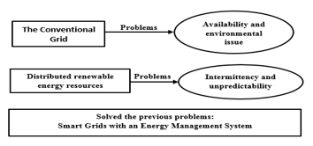 Figure 1: several problems with solutions for the classical grid
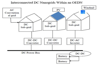 Figure 2: The structure of interconnected DC Nano grids within an OEDS
3. A Modified DC-Nanogrid against Traditional One
The standard DC nano-grid requires a 2-stage AC-DC power conversion system to support both DC and AC loads. So, its design has several challenges as it involves a great number of converters and inverters, as seen in Figure 3. Moreover, different separated security and control algorithms are needed for each stage. This series of conversions rises the system total cost and losses.
But on the other hand, a single-stage conversion system was proposed to overcome some drawbacks mentioned in the standard one. Those updated nanogrids are modified with few numbers of conversion stages [12-14].
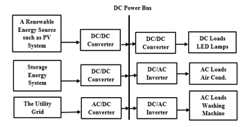 Figure 3: The standard nanogrid structure
Table 1: Show a comparison between OEDN and single nanogrid system
| An OEDS | Single nanogrid |
| Power generated is uncentralized | Power generated at the end user |
| 50 – few hundred households | Less than 50 households |
| Coverage ranges from a few hundred meters to 1-2 kilometres |
Coverage ranges less than 100 metres |
| Need a few large numbers of DC / AC conversion sets | A few numbers of DC/AC inverters are required |
4. A Single Input Multi Output – Converter
The suggested modified DC nanogrid system is based on a single entry switched boost inverter (SBI) as shown in figure 4. SBI is a single-stage power converter capable of providing DC and AC loads simultaneously from the same DC input voltage. It can also provide an output AC voltage whether higher (boosting) or lower (bucking) than its DC input voltage. It prevents noise due to electromagnetic interference (EMI) compared with the classical two stage power converters [14]. Moreover, SBI doesn’t need to a dead time circuit as its operation technique depends on the shoot-through state. The SBI operation is originated its basic concept from the Inverse Watkins topology and the Z-source inverter (ZSI) operating idea. But, the SBI has many benefits compared with the ZSI – as explored in table 2 [15-19].
4.1. Topology of a Single Stage Switched Boost Inverter
The circuit diagram of the SIMO-SBI contains five IGBT switches, two passive elements (an inductor (L) with capacitor (C)), two diodes ( , ), and a low pass LC passive filter is connected across the AC output of the inverter to mitigate un-desirable harmonic components as shown in figure 5. SBI has two operating modes non-shoot through state mode and shoot through state mode. The AC Output voltage of the SBI can be controlled by the following equations:
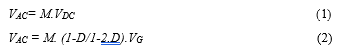
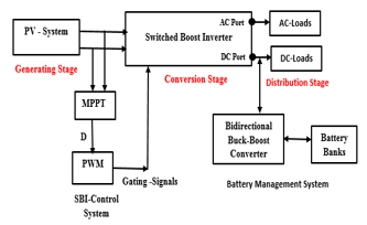 Figure 4: Block diagram for the suggested modified DC nanogrid
Table 2: Comparison between ZSI and SBI
| SIMO
Inverters |
Active Switches | Reactive switches | Noise Interference | Accuracy |
| SBI | More | Less | Less | More |
| ZSI | Less | More | More | Less |
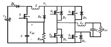 Figure 5: The Circuit diagram of the SIMO-SBI
So, M and D are chosen in such a way to control its peak output AC voltage ??? . Also, the sum of shoot-through duty ratio (D) and the modulation index (M) should be less than or equal to unity, i.e.
 4.2. Open Loop Control Algorithm for a SIMO-SBI
The SBI open loop control technique derives its basic idea from the traditional sinusoidal pulse width modulation (PWM) technique. But, the standard PWM scheme should be changed in order to allow use of its shooting-through mode territory. So, this new approach has been used during the positive and negative half periods of the sinusoidal modulation signal Vm (t). The SBI open loop control algorithm was discussed in details in [9, 20]. SBI doesn’t need to a dead time circuit in its operation technique. On the other hand, its main drawback was summarized in its limiting duty ratio (D) (0-0.5) which cause high harmonics in its output voltages when the duty ratio gets closer to the end of the range (0.4 – 0.5).
Figures 6 and 7 are included as samples in the process of main-parameter changes manually for SBI to adjust its performance before interconnection. Figure 6 demonstrates the performance of the switched boost inverter as a buck converter to obtain an AC output voltage less than its DC input at duty ratio equal 0.22.
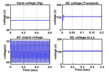 Figure 6: The SBI operation in a bucking mode (with D=0.22)
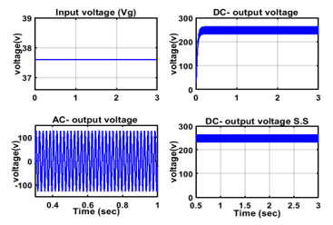 Figure 7: The SBI operation in a boosting mode with (D=0.4515)
While, figure 7 illustrates the performance of the inverter as a boost converter and to raise AC output voltage higher than its DC input with a duty ratio equal 0.4515. So, the robust closed loop control should be used to maintain the SBI output voltages constant, especially through the critical range of the duty ratio (0.4 – 0.5).
4.3. Closed Loop Control Algorithm for a SIMO-SBI
The purpose of the closed loop control is to keep the system stable even after it has been subjected to a certain variety. The output of the inverter is highly sensitive to any slight change in its duty ratio [19].
As, the output of the inverter will go to infinity if the system duty ratio (D) is 0.5. And the system output is observed to be erratic with a very high percentage of harmonics when its duty ratio becomes closer to 0.45. So, the system DC output voltage of the SBI should be controlled by using a robust closed-loop control algorithm to keep it constant.
This control algorithm is mainly depending on comparing the DC output voltage and the DC reference voltage and the resulting error is managed by a PID control strategy. The PID controller was chosen due to its simplicity, easy in continuous tuning, provides good stability, and rapid response. The parameters of the PID controller were designed based on the Ziegler-Nichols formulas. The proportional, integral, and derivative gains are selected as [20]:
![]() The output of this controller is used to readjust the PWM pattern applied to the inverter switches. This controller strategy is applied to overcome the disadvantages of the inverter and to monitor its DC output value. As a consequence, its AC output voltage will regulate according to Equation 2, at a constant modulation index (M=0.5), as discussed in details in [10].
The output of this controller is used to readjust the PWM pattern applied to the inverter switches. This controller strategy is applied to overcome the disadvantages of the inverter and to monitor its DC output value. As a consequence, its AC output voltage will regulate according to Equation 2, at a constant modulation index (M=0.5), as discussed in details in [10].
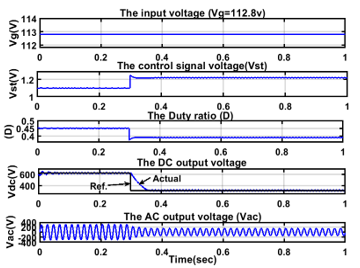 Figure 8: The input voltage, control signal, the duty ratio, the DC/AC output voltages respectively by decreasing the reference voltage from 622 to 311v.
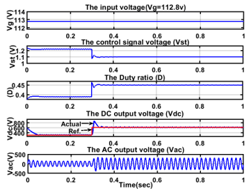 Figure 9: the input voltage, control signal, the duty ratio, the DC/AC output voltages respectively by increasing the reference voltage from 311 to 622v.
For insurance of the robustness of the controller in maintaining the DC-link voltage constant before interconnection the following sample figures test the time response of the closed loop control under disturbances. Figures 8 ,9 demonstrates the system response to the sudden increase/ decrease in the DC reference output voltage of the SBI ( from (622 to 311 V) and vice versa (with step time 0.3). This robustness of the controller keeps the inverter DC output voltage constant. This can be achieved for each interconnected modified DC nanogrid to form a complete stable OEDN.
Hence, each proposed modified DC nanogrid in the OEDN contains solar photovoltaic (PV) arrays supply as a renewable energy distributed generation (DG). Although PV is a clean, pure, natural replenished resource, and environmental friendly, but also is an intermittent resource that is very sensitive to the sun’s heat, temperature, humidity and climatic conditions. So, this standalone system will require a power storage scheme such as batteries to retain the excess energy produced from the renewable PV systems. Also, storage system supplies energy in the load peak hours, or through nights and cloudy days.
However, the battery storage system is connected to the system via a bi-directional buck-boost converter that control the battery loading / unloading algorithm. This converter interconnects between both sides of the SBI DC-bus and the lead acid battery banks. This will happen during the charging process of the battery bucking the voltage of DC-link from 622 V to 240V of the battery-bank voltage. On the other hand, through discharging process, it operates as a booster to raise battery voltage form 240V to the DC-link voltage (i.e., 622V). This process can be achieved through a sophisticated algorithm discussed in [10, 20]. This technique guarantees consistency of operation of the scheme without a lack of load requirements. The block diagram for the battery management system is shown in figure 10.
5. The Open Energy Distribution Network (OEDN) Control Algorithm
The SBI robust closed loop control technique allows to maintain the DC-nanogrid output voltages constant under different system operating conditions. It allows for smooth power transfer from one nanogrid to another by applying a simple additional control algorithm to manage the load demands [21,22]. The OEDN control algorithm is depending on a bi-directional controlled-switch that is used to allow power flow between the adjacent nanogrids as seen in Figure 11.
In the proposed system, the control signal turns the switch Sng1 on when any of either the DC or AC load requirements of nanogrid 1 is lower than that obtained from its PV source. So, The Sng1 is turned on to allow the excess power to transfer easily and smoothly from grid 1 to grid 2. While, the control signal turns the switch Sng2 on when any of either the DC or AC loads requirements of nanogrid 2 is lower power than that obtained from its PV source.
In other words, nanogrids with different values of generated power will able to transfer excess power between them according to load demands. As a consequence, this control algorithm allows the smooth flow of excess power from one grid to another. The regulation of the working switches is relying mainly on the signal from the output of the comparator control algorithm is facilitating the energy swap between several interconnected nanogrids in an OEDN. Figure 12 introduced the control schematic diagram and Figure 13 provides in details the flow chart for this proposed algorithm.
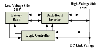 Figure 10: Battery management system
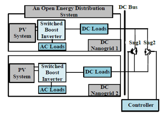 Figure 11: The block diagram for an OEDS control system
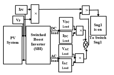 Figure 12: The two interconnected nanogrids control algorithm
5.1. Case study: an OEDN-based two DC-nanogrids
The following results introduce the efficiency of the proposed OEDN control algorithm to operate stably under various conditions. They also demonstrate the performance of the SBI output voltages with its rigorous robust closed loop control technique. Matlab / Simulink software package was used in modelling and simulation of the proposed system [23].
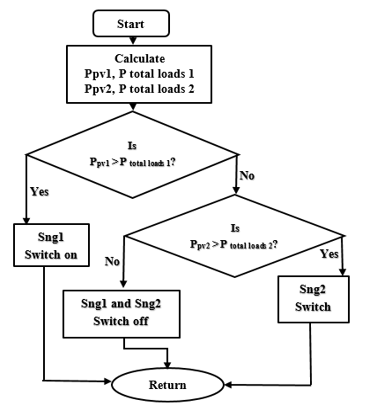 Figure 13: The OEDS controller flow chart
The Following test results demonstrate the system robustness under different conditions. Figures 14 and 15 show the flow of power in a full OEDN with two interconnected grids from separate solar generators. All nanogrids are energized from independent solar generators with checking stability of the overall control system under any fault conditions within the same OEDN. Each figure shows the AC, DC output and the total load powers for the two DC-interconnected nanogrids within an OEDN .
Figure 14 shows that the generating power of one grid PV source is 6 kW and 4.5 kW for other. If the load of the first one will consume the full power in the first 0.4 sec. Then, if the power of that load are distributed abruptly and minimizing its consumption to just 4.5 kW. At the same time, the demands of the other load in (NG2) increased and need to this excess power to its load.
So, the extra power of the first nanogrid will transfer in the same time to the load of other grid to compensate the power shortage. At this instant (i.e., t=0.4 Sec.), the demand power for other grid will be increased to 1.5 kW. As a sequence, figures 14 ((a) and (b)) represents the AC and DC output powers of both interconnected nanogrids followed by the total load power with their different requirements at 0.4 sec (as shown in figure 14c).
While, figure 15 shows two other nanogrids with different generating powers. As, the first nanogrid with a PV source of rating 6.5 kW. The utilities of this nanogrid consume all power through 0.4 sec. Then, Its consumption is reduced to just 5.5 kW. So, the extra power of the first nanogrid will transfer in the same time to satisfy the shortage of power in the other nanogrid loads. The previous two cases ensured the system ability of the exchange power stably between the interconnected modified DC nanogrids in an OEDN.
Note: if there is a surplus power from Ng1 and Ng2, then this excess power will be transferred to the battery banks for storage and emergency use.
(a) The power consumed by AC- loads for both nanogrids
(b) The power consumed by DC- loads for both nanogrids
(c)The total interconnected power transferred for both nanogrids
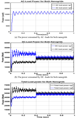 Figure 14: AC,DC and total power of the two PV-based nano-grids with rated generated power of values 6 and 4.5 kW respectively
6. Conclusion
This paper explored the importance of the DC interconnection and DC distribution systems. It identified a perfect design for the OEDN with interconnected DC grids. A bi-directional robust control technology was introduced to assure an efficient energy transmission between the linked DC nanogrids. It guarantees the system optimum operation even if any of the grid generating sources are cut off. Thusly, it converted the centralized scheme to a decentralized one with high reliability of mental process.
Moreover, The modified, adapted SIMO power electronic SBI with its adaptive monitoring control system was carried out in each nano-grid. It tends to ameliorate the performance of the inverter by adjusting its outputs to high levels. In this mode, it allows the AC output voltages to be grown to a value (220 V rms) which is suitable for the loads in EGYPT.
Also, DC-interconnection among nanogrids is suitable and efficient more than AC in the two cases (autonomous off – and on-grid) systems.
- The power consumed by AC- loads for both nanogrids
- The power consumed by DC- loads for both nanogrids
- The total interconnected power transferred for both nanogrids
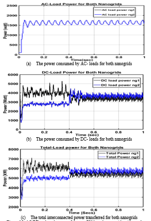 Figure 15: AC,DC and total power of the two PV-based nano-grids with rated generated power of values 6.5 and 5 kW respectively
Conflict of Interest
The authors declare no conflict of interest.
Acknowledgment
This research is supported by the Electronics Research Institute, (ERI), Egypt.
- P. Asmus, “Microgrid, virtual power plants and our distributed energy future,” The Electricity Journal, 23(10), 72–82, 2010, doi: 10.1016/j.tej.2010.11.001.
- A. Raheem, S.A. Abbasi, A. Memon, S.R. Samo, Y. H. Taufiq-Yap, M.K. Danquah, R. Harun, “Renewable energy deployment to combat energy crisis in Pakistan.,” Energy, Sustainability and Society, 6(1), 1-13, 2016, doi: 10.1186/s13705-016-0082-z.
- C. Marnay, B. Nordman, J. Lai, “future roles of milli-micro and nano-grids,” CIGRÉ International Symposium, the Electric Power System of the Future-Integrating Super-Grids and Microgrids, Bologna, Italy, 2011.
- A. Werth, N. Kitamura, K. Tanaka, “conceptual study for open energy systems: distributed energy network using interconnected DC nanogrids,” IEEE Transactions on Smart Grid, 2(4), 1621- 1630, 2015, doi:10.1109/TSG.2015.2408603.
- R. Adda, O. Ray, S. Mishra, “implementation and control of switched boost inverter for DC nano-grid applications”, IEEE Energy Conversion Congress and Exposition, USA, 15-20, 2012, doi: 10.1109/ECCE.2012.6342289.
- D. Burmster, R. Rayudu, W. Seah, D. Akinyele, “A review of nanogrid topologies and technologies,” Renewable and Sustainable Energy Reviews, 67, 760-775, 2017, https://doi.org/10.1016/j.rser.2016.09.073.
- O.D. Castle, A. El Shahat. “Single-input-multi-output (SIMO) converter for nano-grids applications,” South east Con IEEE, 1-5, 2017, doi: 10.1109/SECON.2017.7925282.
- R. Adda, O. Ray, S. Mishra,” synchronous-reference-frame-based control of switched boost inverter for standalone DC nanogrid applications,” IEEE Transactions on Power Electronics, 3(28), 1219-1233, 2013, doi: 10.1109/TPEL.2012.2211039.
- E.A. Ebrahim, N.A. Maged, N. Abdel-Rahim, F. Bendary, “a novel approach of a single input multi output switched boost inverter,” JEE Journal of Electrical Engineering, 3(3), 90-101, 2018, Corpus ID: 220422035.
- E. A. Ebrahim, N.A. Maged, N. Abdel-Rahim, F. Bendary, “Closed-loop Control of a Single-Stage Switched-Boost Inverter in Modified DC-Interconnected Nano-grids,” IET, The Journal of Engineering (JoE), 2020(10), 843-853, 2020, doi: 10.1049/joe.2019.1248.
- M. C. Falvo, L. Martirano, “From smart grids to sustainable energy microsystems,” Proc. 10th Int. Conf. Environ. Elect. Eng., Rome, Italy, May 2011, doi: 10.1109/EEEIC.2011.5874756.
- M. Brenna, M. Falvo, F. Foiadelli, L. Martirano, D. Poli, “sustainable energy microsystem (SEM): preliminary energy analysis,” IEEE PES Innov. Smart Grid Technol. (ISGT), Washington, DC, USA, 1–21, 2012, doi: 10.1109/ISGT.2012.6175735
- A.S. Shilpa, H.V. Shetty,” Switched Boost Inverter with PWM Control and Development of a Prototype Model,” International Journaln of Advanced Research in Electrical , Electronic and Instrumentation Engineering, 8(3), 2014. doi: 10.15662/ijareeie.2014.0308011
- R. Adda, S. Mishra, A. Joshi, “A PWM Control Strategy for Switched Boost Inverter,” IEEE Energy Conversion Congress and Exposition (ECCE), 991-996, 17 Sep. 2011, doi: 10.1109/ECCE.2011.6063880.
- P.C. Loh, D.M. Vilathgamuwa, Y.S. Lai, G.T. Chua and Y. Li, “Pulse-Width Modulation of Z-Source Inverters,” IEEE 39th IAS Annual Meeting. Conference in Industry Applications Conference, 20(6), 1346 – 1355, 2004, doi: 10.1109/IAS.2004.1348401.
- B. Ebrahim, M.H. Nozadian, E.S. Asl and S. Laali. “Developed embedded switched-Z-source inverter,” IET Power Electronics, 9(9), 1828-1841, 2016. doi: 10.1049/iet-pel.2015.0921.
- Y. Huang, M, Shen, FZ. Pengand and J. Wang, “Z -Source Inverter for Residential Photovoltaic Systems,” IEEE Transactions on Power Electronics, 3(6), 1776-1782, 2006, doi: 10.1109/TPEL.2006.882913.
- J. Liu, J. Hu, L. Xu, “Dynamic Modeling and Analysis of Z – Source Converter—Derivation of AC Small Signal Model and Design-Oriented Analysis,” IEEE Transactions on Power Electronics, 7(5), 1786-96, 2007, doi: 10.1109/TPEL.2007.904219.
- M.K. Nguyen, Y.C. Lim, S.J. Park, “A Comparison between Single-Phase Quasi- Z-Source and Quasi-Switched Boost Inverters,” IEEE Transactions on Industrial Electronics, 62(10), 6336-6344, 2007, doi: 10.1109/TIE.2015.2424201.
- N.A. Maged, DC-based energy distribution system for Inter-connected nano-grids, M.Sc. thesis, Benha University, Egypt, 2018.
- E. A. Ebrahim, N.A. Maged, N. Abdel-Rahim, F. Bendary, “Photovoltaic-Based Interconnected-Modified DC-Nanogrids within an Open Energy Distribution System.,” 6th International Conference on Advanced Control Circuits and Systems (ACCS) & 2019 5th International Conference on New Paradigms in Electronics & information Technology (PEIT). IEEE, 253-258, 2019, doi: 10.1109/ACCS-PEIT48329.2019.9062843.
- E. A. Ebrahim, N.A. Maged, N. Abdel-Rahim, F. Bendary, “ DC-Based Interconnected-Modified Nanogrids within an Open Energy Distributed System (OEDS),” CIRED conference, 25th International Conference on Electricity Distribution, 2019, http://dx.doi.org/10.34890/992.
- Math Works, Matlab / Simulink User’s Guide, Math Work Co., USA, 2014.
No related articles were found.