Development of Hexa Spacer Damper for 765 kV Transmission Lines’ Vibration Damping
 , Sumana Chattaraj 2, Dharmbir Prasad 3, Rudra Pratap Singh 3, Md. Irfan Khan 4, Harish Agarwal 4
Adv. Sci. Technol. Eng. Syst. J. 6(1), 472–478 (2021);
 DOI: 10.25046/aj060151
In this paper, hexa spacer damper is proposed and its vibration damping effect on the 765 kV power transmission network under the influence of fluctuating wind (10-60 Hz) loading is validated. This asymmetrical loadings led the bundle of Zebra ACSR conductor to be twisted and hence, cause mechanical and electrical instabilities across the span length. These issues may be addressed using the undertaken spacer damper. This paper highlights design, development and field tests of the proposed solution. The product has been validated using CATIA V5 software tools and for the field trial – 27 numbers of these dampers have been placed at various sub-spans across the line at Hydro Québec Test Station, Canada. The damping efficiency has been recorded using system integrated data acquisition set up. The proposed products are an important item of overhead line hardware and are extensively used to ensure that bundled conductors to provide mechanical and electrical performance reliability in service.
1.Introduction
Today, energy has become prime necessity of growing population’s livelihood and simultaneously reliability of the transmission network is vital for uninterrupted power supply service [1]. It’s quite common to transmit the power at higher voltage level (like HV, EHV and UHV) for keeping the various losses within the permissible limits [2]. Thus, application of conductor bundling is widely adopted method to nullify the impact of voltage gradient, and hence reduction in cascading losses causes by radio interference and corona and meeting economical aspects of project deployment. The conductor bundling is get affected due to wind and ice load twisting effect, which may further led to interruption in transmission service [3-5]. For transmission line there are various parameters are considered at the time of erection and commissioning. Among all these parameters one of the most important thing is the vibration on the ACSR conductors [6, 7]. Most of the general issues are comes from this scenario even it affects communication lines too [8, 9]. The conductors are attached to the towers through rigid contacts for reducing the chances of failure, but if the wind speed is preferably higher then there might be extensive chances of vibration on the conductors. At this situation the rigid supports on the structure exerts shear force on the conductor and as a result they can fail. To get rid of this situation, we cannot apply some flexible coupling of the conductors on the tower to reduce the vibration effect. One most effective way to reduce it by application of spacer damper on the conductor, it is possible only if the conductors are very close to each other [10]. The spacer damper provides a constant space between the conductors as well as due to the damping characteristics of rubber padding on the arms it also provides an effective damping so that the chances of failure on the conductor coupling on the joint locations can be reduced.
In continuation with introduction, remaining portion of the paper is presented as: construction overview has been studied in Section II and related mathematical derivation in Section III. The proposed spacer damper has been virtually modeled in Section IV. Thereafter, in Section V, a description of field experimentation has been presented. Finally, the current study has been concluded in Section VI.
2. Constructional Overview
The spacer damper is to be required for mainly keeping a safe distance between conductors’ bundle [11]. This type of damper is aluminum made rigid focal casing with numbers of arm count based on number of conductors in a bundle of particular transmission line [12]. In this study, a hexa spacer damper has been proposed for undertaken transmission line. Its shape is equilateral hexagon and the clamp body is made of aluminium (Al) alloy, which is connected with rigid frame at centre to provide effective gripping to the conductor. Major parts of the proposed damper have been presented in Table I.
Table 1: Specification of major components involved in tests.
| S. No. | Particulars | Features | Quantity | |
| 1 | Body of clamp | Al alloy | 1 | |
| 2 | Arm of clamp | Al alloy | 6 | |
| 3 | Holding sleeve | Al extrusion | 6 | |
| 4 | Cushion for damping | Neoprene rubber | 6 | |
| 5 | Washer | Steel HDG | 6 | |
| Properties of applied conductor | ||||
| 6 | Diameter of applied conductor | 28.6 mm | ||
| 7 | Strands of ACSR conductor (Zebra) | 54/7 | ||
| 8 | Applied conductors count | 6 | ||
| 9 | Mass/ length of conductor | 1.621 kg/m | ||
| 10 | Maximum bending amplitude | 265 μm | ||
| 11 | Nominal tension of applied conductor | 35 kN | ||
| 12 | Rated value of tensile strength | 131.9 kN | ||
For damping sub-conductors’ vibration energy at connecting point, an elastomeric bush has been used in-between clamp arms and supporting frame. And the spacer body too highly flexible in order to sustain such vibrations and damping.
3. Mathematical Modeling
In this section, mathematical modeling of the proposed solution has been carried out before initiating product development and applicable field testing. Here, Figure 1 shows the load application on the hexa-spacer damper. We have evaluated the load application and as per the design concept by the help of force component division we have applied the loads.
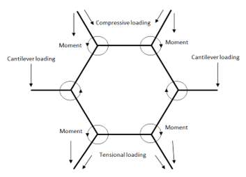 Figure 1: Loading application on the main structure
For the application of loads first on the manual mathematical calculation we have shown general mathematical expressions related to the vibration force and static loads due to the conductor weight. For the scenario of damping and loading three types of loadings are to be considering here these are elastic force, damping force and pounding force. The elastic force experienced by the system can be evaluated by a simple mass and spring system. The elastic forces in different directions can be taken as (1) – (3) [6, 13],
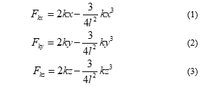 where, represent spring constant and the is the effective length of the spring. For our case, we can assume the length of the arm is the length of the spring or damping damper device.
The damping force is the internal force exerted by the damping device like the rubber padding on the coupling portions of the arms with the main body of the spaced damper. For mathematical evaluation some general formula can be followed, those are stated below (4) – (5) [6, 13]
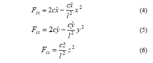 here, is the damping constant for the damping material provided on the product and , and are velocities of the mass block for this case we can say the mass block is the attached conductor to the spacer damper.
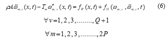
According to the Hertz’s contact law pounding force is stated by one dimensional but for our system we have evaluated this for two dimensional points of view. In the present study, safe spacing among six bundle conductors has been kept using hexa spacer damper across the span length as shown in Figure 2. In this diagram, dampers are positioned from the left side using , where, . Total span length segmented into sub-spans like . Corresponding formulation for the conductor bundling has been illustrated in the succeeding section:
This sub-conductor motion (i.e., transverse) of -th sub-span is formulated as by the transverse wave equation as presented in (6) [6, 13],
 Thenafter, conductors’ homogeneous motion equation while ignoring the aerodynamic forces will be simplified as (7) [6, 13],
![]() Here, considering both horizontal and vertical tension (i.e., where ) to be same for the sub-conductor. Therefore, segregation of dependent factors (like time and space) from the displacement quantity may be formulated as in (8) – (9) [6, 13]
Here, considering both horizontal and vertical tension (i.e., where ) to be same for the sub-conductor. Therefore, segregation of dependent factors (like time and space) from the displacement quantity may be formulated as in (8) – (9) [6, 13]
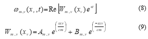 where, among two different traveling waves of -direction; its negative one pertaining towards amplitude while positive one amplitude.
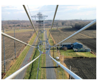 Figure 2: Field test layout of the proposed damper.
4. Virtual modeling of Spacer Damper
Software simulation is one of the most effective solutions for getting the behavior of the product on loading conditions. Here, we have used CATIA V5R20 for its three-dimensional design with proper dimensions and have also performed its load simulation testing on this product. The loadings are basically compound loading on the structure and as per the loaded condition on the structure we are just showing the mechanical characteristic and its material properties has been presented in Table II. Since, we have to check the stability of the device in loaded condition therefore; we have to show the failure mode analysis. After selecting the material on the product the further step is to define the boundary conditions on the structure. Boundary conditions are the possible parameters taken as input for applying the loads on the above stated structure. If the boundary conditions are not specified properly then there will not be a meaning of actual load testing. Corresponding simulation results has been presented in Figure 3 – 6.
Table 2: Material parameters
| Material | Aluminum |
| Young’s modulus | 7e+010N_m2 |
| Poisson’s ratio | 0.346 |
| Density | 2710kg_m3 |
| Coefficient of thermal expansion | 2.36e-005_Kdeg |
| Yield strength | 9.5e+007N_m2 |
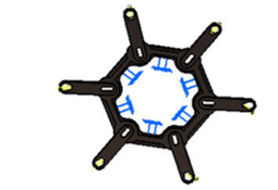 Figure 3: Applying boundary condition on the product
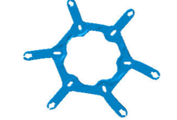 Figure 4: Meshing and deformation for load application
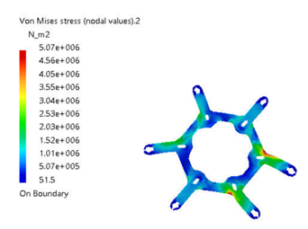 Figure 5: Stress concentration (Von-mises stress with color code scaling)
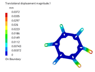 Figure 6: Translational displacement (Deformation with color code scaling)
5. Experimentation at Site
With the increase in demand for electricity all over the world, the span and the number of bundle for transmission line are showing a trend of increase [14]. Thus, to improve reliability of 765 kV transmission line spacer dampers (27 numbers) should be deployed across the transmission line as presented in Table III. The data acquisition sequence is chosen using software developed at IREQ based on LabVIEW programming language. The hardware used for the data acquisition is from National Instruments. The data acquisition system utilizes the most recent technology including fiber optic to carry the transducer signals which has low latency hence precise time graph analysis. Vibration amplitudes are measured according to industry standards [9]. The data acquisition loop begins with the acquisition of the weather data: more precisely wind velocity; azimuth and elevation as well as air temperature at a rate of 10 points per second (pts/sec) during 300 sec.
Table 3: Spacer damper installation across the undertaken transmission line.
| Span (m) | Spacer
damper counts |
Sub-span (m) |
| 150 | 3 | 30 – 47 – 43 – 30 |
| 400 | 7 | 32 – 51 – 55 – 59 – 63 – 57 – 51 – 32 |
| 450 | 7 | 35 – 58 – 62 – 66 – 69 – 65 – 60 – 35 |
| 425 | 7 | 34 – 54 – 58 – 63 – 66 – 62 – 54 – 34 |
| 150 | 3 | 30 – 47 – 43 – 30 |
Wind velocity, azimuth and elevation are measured using four ultrasonic anemometers [15, 16]. On the other hand, the processing or using the discrete spectral frequencies has been adopted. Only those recordings with an apparent frequency in the range between 0.6 – 2.5 Hz were selected. In this paper, we have validated mechanical strength of the spacer damper to check sustainability of different body parts while conductors abnormality in oscillations.
 Figure 7: Maximum P-P displacement in sub-span.
In the field test, as part of apparent frequency the P-P amplitude is noted in Table IV as relentless cycle behavior. Thenafter, corresponding graphical analysis of the results is presented in Figure 7. For further study (like – vector and matrix), the conductor has been considered as located at certain height with a maximum span ( i.e., 450 m) and getting affected under wind exposure. This particular circumstance reflecting actual field test oscillation effect on the installed spacer damper, which has been plotted in Figure 8 to highlight wind exposition at the site. While covering this field test a wide range of velocities in various directions based on sub-span oscillations and Aeolian vibrations have been taken. Furthermore, the bending-amplitude (RMS) of the conductor will be evaluated [17], and results are graphically compiled in Figure 9.
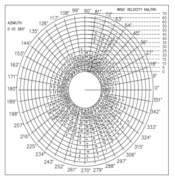 Figure 8: Wind-expositions’ polar plotting
Table 4: Peak-peak displacement (maximum).
| Sub-span | P-P displacement (mm) | Maximum (mm/s) |
| 1 | 26 | 8.5 |
| 2 | 60 | 10 |
| 3 | 56 | 13 |
| 4 | 59 | 11 |
| 5 | 56 | 14 |
| 6 | 79 | 12 |
| 7 | 52 | 10 |
| 8 | 28 | 7.8 |
here, the bending-amplitude (RMS) value in sub-spans is recorded and then graphically presented in Figure 11. While, asses this particular graph, it may be seen that its variation is upto 80 mm/s value.
The averaged value of which is 5 km/h at an interval of 10º is presented in Table 5. It has been found a variation of azimuth angle 270º – 280º with wind speed covering about 50- 55 km/h.
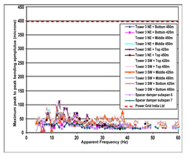 Figure 9: Bending-amplitudes’ maximum (RMS) value.
Table 5: Results of (maximum value)
| Sub-spans | (mm/s) | Wind conditions | |
| Azimuth angle (o) | Velocity
( in km/h) |
||
| 1 | 4.4 | 270 – 280 | 50 – 55 |
| 2 | 6.3 | 270 – 280 | 50 – 55 |
| 3 | 6.1 | 270 – 280 | 50 – 55 |
| 4 | 5.7 | 270 – 280 | 50 – 55 |
| 5 | 6.4 | 270 – 280 | 50 – 55 |
| 6 | 6.5 | 270 – 280 | 50 – 55 |
| 7 | 5.6 | 280 – 290 | 45 – 50 |
| 8 | 4.4 | 270 – 280 | 50 – 55 |
6. Conclusions
The product has been designed and validated using CATIA V5 software tools before initiating field trials. Since, we have applied the loads on the structure as per the weights of the conductors and according to those loading we have the output results for stress concentration and deformation therefore it is now very easy to conclude the mechanical load capacity of the proposed model. We have used a loading of 1621 kg per km of conductor, the span between two towers are 425m and according to that conductor weights will be 688.925kg. Now the usage of spacer dampers on this span is 7 so we can say each arm of the damper carrying a load of 98.417 kg in different modes like compression and tension. After application of this load we have found the maximum stress concentration on this product is which is quite preferable for the product as well as the material used as Aluminum. Along with it for the compound load application the maximum deformation on the structure is 0.0327 mm. The value of deformation is very less. Therefore, as a final conclusion we can say the product is structurally strong enough to sustain the applied load on it. The proposed solution’s feasibility could be checked from Table 6.
Table 6: Summary of recorded field results.
| Particulars | Standards | Findings |
| Clamps peak-peak bending amplitude (max) | < 398 μm | 141 μm |
| Clamps RMS bending amplitude (max) | < 80 μm | 29 μm |
| Peak-peak (max) displacement for sub-span oscillations | < 350 mm | 79 mm |
| (max) for sub-spans | < 80 mm/s | 14 mm/s |
| (mean) for site wind | < 70 mm/s | 6.5 mm/s |
Conflict of Interest
The authors declare no conflict of interest with any other individual or organization.
Acknowledgement
Authors are thankful to Mechanical and Environmental Testing Laboratory of Hydro Québec Test Station, Canada for facilitating the hexa-spacer damper field trials.
Appendix
The computational data associated with its design is presented in Appendix A.
- Power Sector at a Glance ALL INDIA, Central Electricity Authority, Government of India. (Accessed on 30th Nov, 2020)
- R.D. Begamudre, “Extra high voltage AC transmission engineering”, New Age International, 2006.
- R. Claren, G. Diana, F. Giordana, E. Massa, “The Vibrations of Transmission Line Conductor Bundles”, IEEE Trans. Pow. App. Sys., PAS-90(4), 1796-1814, 1971. DOI: 10.1109/TPAS.1971.293173
- L.E. Kollár, M. Farzaneh, “Vibration of bundled conductors following ice shedding”, IEEE Trans. Pow. Del., 23(2), 1097-1104, 2008. 10.1109/TPWRD.2007.915876
- S. Mukherjee, S. Chattaraj, M.K. Shaw, P. Barua, D. Prasad, “Control of Wind-Induced Instabilities associated with Conductors through application of Dampers”, IEEMA J., 10(4), 58-62, 2018.
- S. Mukherjee, D. Prasad, M.I. Khan, P. Barua, H. Agarwal, “Hexa Spacer Damper for Vibration Energy Decaying of 765 kV Transmission Line”, In 2019 Innovations in Power and Advanced Computing Technologies (i-PACT), 1, 1-6, 2019. DOI: 10.1109/i-PACT44901.2019.8960087
- IEEE T&D Committee, “Standardization of conductor vibration measurements”, IEEE Trans. Power App. Syst, 85(1), 10-12, 1996. DOI: 10.1109/TPAS.1966.291515
- K. Anderson, P. Hagedorn, “On the Energy Dissipation in Spacer Dampers in Bundled Conductors of Overhead Transmission Lines”, J. Sound Vib., 180(4), 539-556, 1995. doi.org/10.1006/jsvi.1995.0099
- D. Prasad, R.P. Singh, S. Mukherjee, S. Chattaraj, K. Sarkar, M.I. Khan, 2020. Approaches to smart grid network communication and security. In Advances in Smart Grid Power System, 103-158, Academic Press, 2020. doi.org/10.1016/B978-0-12-824337-4.00005-9
- N.A. Saadabad, H. Moradi, G. Vosoughi, “Semi-active control of forced oscillations in power transmission lines via optimum tuneable vibration absorbers: With review on linear dynamic linear aspects”, Int. J. Mech. Sci., 87, 163-178, 2014. doi.org/10.1016/j.ijmecsci.2014.06.006
- E.S. Abd-Elaal, J.E. Mills, X. Ma, “A review of transmission line systems under downburst wind loads”, J. Wind Engg. Ind. Aero., 179, 503-513, 2018. doi.org/10.1016/j.jweia.2018.07.004
- F. Foti, L. Martinelli, “A unifield analytical model for the self-damping of stranded cables under Aeolian vibrations”, J. Wind Engg. Ind. Aero., 176, 225-238, 2018. doi.org/10.1016/j.jweia.2018.03.028
- F. Kiessling, P. Nefzger, J.F. Nolasco, U. Kaintzyk, “Overhead power lines: planning, design, construction”, Springer, 2014.
- A. Sakhavati, M. Yaltagiani, S.S. Ahari, S.M. Mahaei, “765 kV transmission line design (Electrical section)”, Int. J. Electr. Comp. Engg (IJECE), 2(5), 698-707, 2012. http://dx.doi.org/10.11591/ijece.v2i5.1591
- P.W. Davall, M.M. Gupta, P.R. Ukrainetz, “Mathematical Analysis of Transmission Line Vibration Data”, Elec. Pow. Sys. Res., pp. 269-282, 4(1), 1978. doi.org/10.1016/0378-7796(78)90013-5
- H. Verma, “Aerodynamic and structural modeling for vortex-excited vibrations in bundled conductors (Doctoral dissertation, Technische Universität)”, 2009.
- J. Chan, D. Havard, C. Rawlins, G. Diana, L. Cloutier, J.L. Lilien, C. Hardy, J. Wang, A. Goel, “EPRI Transmission Line Reference Book: wind-induced Conductor Motion”, 2009.