Lightning Detection System for Wind Turbines Using a Large-Diameter Rogowski Coil

Adv. Sci. Technol. Eng. Syst. J. 10(1), 1–6 (2025);
 DOI: 10.25046/aj100101
A lightning detection system based on a large-diameter Rogowski coil and an analog integrator was developed for wind turbine applications and is presented in this paper. To accurately detect lightning current, the Rogowski coil was designed with a lower cutoff frequency of 0.1 Hz. The analog integrator, comprising an inverting active integrator, and an amplifier, was used to restore the original waveform of the lightning current. Tests were conducted to verify the bandwidth of the system using alternating current, damped sinusoidal current, and a rectangular pulse. The system demonstrated a bandwidth of 0.1 Hz to 100 kHz, which is within the standard acceptable range. This lightning detection system offers a significantly lower cost compared to commercial alternatives, making it highly suitable for practical applications.
1. Introduction
For sustainable development and achieving carbon neutrality, wind turbines are increasingly being used for power generation [1]. Over the past decade, Japan has been the second-largest wind power installer in the world, with a cumulative capacity of 5,213 MW [2]. Wind turbines operate effectively in areas with strong winds, such as coastal or offshore locations, but this also places them at a high risk of being struck by lightning [3]-[5]. It is important to stop wind turbines and perform manual inspections after a lightning event is detected to prevent further damage and ensure safety. To achieve this, a lightning detection system (LDS) is deployed to identify such events.
As stated by the JEM and IEC standards [6],[7], the LDS consisting of a large-diameter Rogowski coil and an analog integrator is one of the alternative methods for the detection of lightning events. In practice, this coil is securely installed at the wind turbine tower near the foundation, wrapped around its exterior. This configuration allows the detection of impulse current from the tower.
Rogowski coil induces voltage is proportional to the time derivative of the lightning current (il), and its transfer function exhibits a positive slope gain. To retrieve the original shape of the lightning current il and maintain its gain constantly, an analog integrator is used. It has a negative slope gain in its transfer function, which cancels out the slope gain of the Rogowski coil.
In this paper, a cost-effective lightning detection system for wind turbine applications is presented. The system has a bandwidth of 0.1 Hz to 100 kHz and comprises a large-diameter Rogowski coil and an analog integrator. The design details are presented in Section 2. Frequency characteristic tests were performed to ensure sufficient bandwidth and are presented in Sections 3 and 4. Finally, the conclusion is presented in Section 5.
2. Lightning Detection System
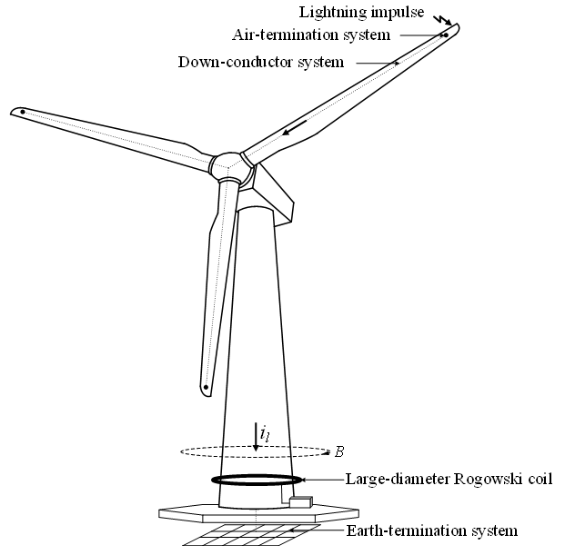
The possibility of a lightning strike at the blade tip of wind turbines is high, as it typically becomes the highest point during operation. A permanently mounted air-termination system, known as a receptor, serves as the contact point between wind turbines and lightning [7]. Once lightning strikes, lightning current il flows from the receptor, a down-conducting system, wind turbine tower, and eventually reaches an earth-termination system at a foundation, as illustrated in Figure 1.
As lightning current il flows to the earth-termination system, it generates a time-varying magnetic field (B) around its conductor. This enables current sensors, such as the Rogowski coil, to detect lightning events if installed anywhere along this current path.
Commercially available Rogowski coil-based LDS units can cost a million yen or more each. In contrast, the developed LDS has a total cost of approximately 33,000 yen, comprising 23,000 yen for the large-diameter Rogowski coil and 10,000 yen for the analog integrator making them significantly cost-effective.
Since the output voltage from the Rogowski coil feeds into the integrator, the frequency characteristics of the LDS can be analyzed by multiplying the Rogowski coil transfer function Hr(s) and the integrator transfer function Hi(s) as in (1)
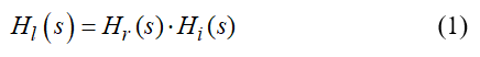
Details for obtaining the Rogowski coil and integrator transfer function are as follows.
2.1. Large-diameter Rogowski coil
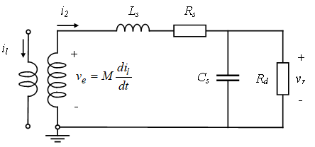
Rogowski coils were introduced in 1912 by German physicist [8]. For simplicity in investigation, it is modeled using lumped parameters, as illustrated in Figure 2, where M represents mutual inductance, Ls represents self-inductance, Rs represents self-resistance, Cs represents stray capacitance, Rd represents damping resistance, i2 represents coil loop current, and vr represents the coil output voltage [9]. Applying Kirchhoff’s voltage law, loop voltage is
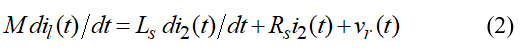
Assume that Ls ∙ di2(t)∕dt ≫ Rs ∙ i2(t) + vr(t), and stray capacitance Cs are neglected, so voltage drops across self-resistance Rs and damping resistance Rd can be neglected. Hence, loop current il(t) ≈ Ls ∙ i2(t) ∕M. This type of coil is known as a self-integrating Rogowski coil, suitable for detecting very short-duration current pulses [10].
To obtain the coil output voltage in the time domain vr(t), apply Kirchhoff’s current law, and the current loop is
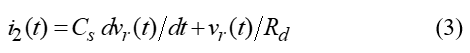
Substitute (3) into (2) and then apply integration with respect to time (t). In practice, stray capacitance Cs and Ls ∕ Rd are assumed to be approximately zero. The voltage drops across self-inductor Ls and the current consumed by stray capacitor Cs can, therefore, be neglected. Thus,
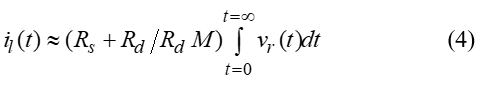
From (4), lightning current il can be reconstructed using an external integrator. This type of Rogowski coil is known as an external-integrating Rogowski coil, which is suitable for relatively long-duration current pulses and was utilized as part of LDS in this study [11].
The frequency characteristics of Rogowski coils can be determined from their transfer function by substituting (3) into (2) and applying Laplace transform. The transfer function of the Rogowski coil, Hr(s), is
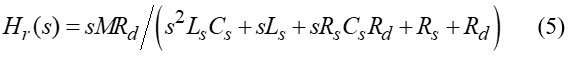
Rogowski coil is a helical toroidal coil of wire. Lead from one end returns to another end through the center of the helical coil. Hence, both terminals are positioned at the same end. Mutual inductance M, self-inductance Ls, stray capacitance Cs, and self-resistance Rs can be calculated from its dimensions as in (6) to (9), respectively [12]-[15].
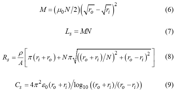
Where ri is the coil inner radius, ro is the coil outer radius, N is the number of turns, u0 is the permeability of free space (4π ×10-7 H/m), ε0 is the permittivity of free space (8.85 × 10⁻¹² F/m), and ρ is the resistivity of the coil wire.
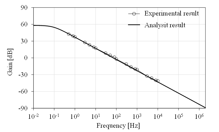
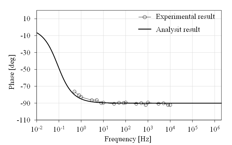
The developed large-diameter Rogowski coil has an inner radius ri of 2 m, allowing it to wrap around the tower of a wind turbine. To achieve a bandwidth of 0.1 Hz to 100 kHz, Rogowski coils are designed with an outer radius ro of 2.04 m and 1400 turns. The coil, made from commercially available wire-reinforced PVC ducting with a diameter of 40 mm, costs approximately 23,000 yen. Aluminum wire is used for the coil, with a cross-sectional area of 1.78 × 10⁻⁸ m² and resistivity ρ of 2.7 × 10⁻⁸ Ω/m. The damping resistance Rd is derived from the impedance of an RG-58 50 Ω coaxial cable, resulting in an infinite damping resistance Rd. From (6) to (9), mutual inductance M, self-inductance Ls, stray capacitance Cs, and self-resistance Rs are calculated as 15.65 µH, 0.22 mH, 766 pF, and 291.3 Ω, respectively. The gain and phase characteristics of the coil, analyzed by (5), are shown in Figure 4 and 5 respectively. It exhibits a linear gain slope of approximately 20 dB/decade and a phase shift of roughly -90 degrees for a frequency range from 0.1 Hz to 100 kHz, which satisfies the target range. The external integrator used with the Rogowski coil has been designed to cancel out the coil gain slope, and the detailed design is presented in the following section.
2.2. Analog Integrator
Analog integrators for the Rogowski coil serve two purposes: to regain the original shape of the lightning current il and to maintain a constant gain. In previous studies, integrators were usually designed with two poles and one or no zeros [10],[16],[17]. The interaction between poles can lead to more complex dynamic behavior in the integrator [18]. The analog integrator used in this study is shown in Figure 3. It is designed to have a single pole with no zero, resulting in more predictable and stable behavior. The analog integrator consists of an inverting active integrator and an amplifier. Bias resistors R2 and R3 minimize the effect of offset voltage, while R5 and R8 limit the bias current. The amplifier circuit is utilized to make it more effective for the digital recorder to record the output voltage vo.
Let Vn and Vp denote inverting and non-inverting operational amplifier (Op-amp) terminal voltages, respectively, with respect to ground. In and Ip denote bias currents entering inverting and non-inverting Op-amp terminals, respectively. For simplicity in analysis, let Vp ≈ Vn, Ip ≈ 0, and In ≈ 0 [19]. The transfer function of the developed analog integrator, Hi(s), is
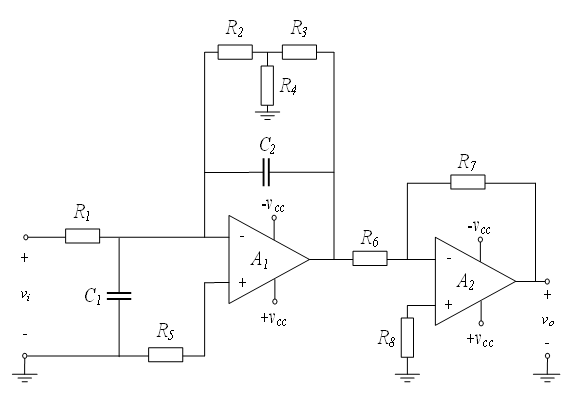
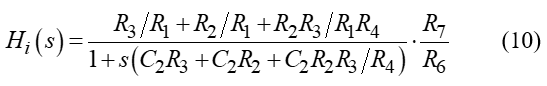
To achieve a gain of about -20 dB/decade and phase shift of-90 degrees from a frequency of 0.1 Hz to 100 kHz, circuit parameters for R1, C1, R2, R3, R4, R5, C2, R6, R7, and R8 were set to 10 kΩ, 2.25 µF, 200 kΩ, 200 kΩ, 100 kΩ, 6.8 kΩ, 2.25 µF, 10 kΩ, 100 kΩ, and 10 kΩ, respectively. Resulting in a pole at approximately -0.556, ensuring the stability of the system. LT112 operational amplifiers were used for both Op-amps A1 and A2 due to their high slew rate of 60 V/µs. Power supplies were used. An output voltage was set to 15 VDC and -15 VDC for Vcc and Vee, respectively. The overall cost of assembling the analog integrator was approximately 10,000 yen. The frequency characteristics of the developed integrator, analyzed by (10), show a linear gain slope of -20 dB/decade and a phase shift of approximately -90 degrees as illustrated in Figure 6 and 7 respectively for the frequency range of 0.1 Hz to 100 kHz, which satisfies the target range.
3. LDS Frequency Characteristic Test
Frequency characteristic tests were performed to verify that LDS is capable of measuring lightning current il without attenuation or phase error. To ensure that each component in the LDS is functioning as designed, three separate frequency characteristic tests were conducted: a bandwidth test on the large-diameter Rogowski coil, the analog integrator, and the LDS.
To demonstrate the alignment between the test results and the analysis, the assessment includes the calculation of the maximum relative error (MRE), defined as
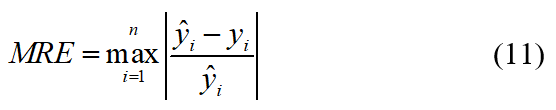
where ŷi and yi represent the ith element of analysis and test result, and n is the total number of considered data points [20].
3.1. Frequency Characteristic Test of the Rogowski Coil
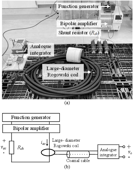
The test was conducted using alternating current (AC) voltage as recommended by the JEM standard [6]. A sinusoidal waveform from a function generator and a bipolar voltage amplifier were used to generate a variable-frequency voltage. A sufficient bandwidth shunt resistor (Rsh) was employed to draw current from the source and serve as a reference current measuring point. Schematic for the test is shown in Figure 8, with the analog integrator removed. The test results for gain and phase shift are presented in Figures 4 and 5 respectively.
At frequencies lower than 100 kHz, the MRE of gain and phase is 0.31 and 0.11, occurring at frequencies of 50 kHz and 1 Hz, respectively, demonstrating good alignment between the analysis and test results. At frequencies higher than 100 kHz, the stray capacitance between each turn of the coil wire becomes significant, impacting the coil characteristics and resulting in large errors between the analysis and test results. However, these frequencies are beyond the intended use and do not affect the overall performance of the LDS.

3.2. Frequency Characteristic Test of Analogue Integrator
To assess the frequency characteristics of the developed analog integrator, a sinusoidal waveform from a function generator was directly applied to the integrator. Comparing the amplitude of the input and output voltages, the test results for gain and phase shift are presented in Figures 6 and 7 respectively. MSE is 2.25 and 0.04 for gain and phase at frequencies of 80 Hz and 0.8 Hz respectively ensuring well alignment of analysis and the test results.
3.3. Frequency Characteristic Test of LDS
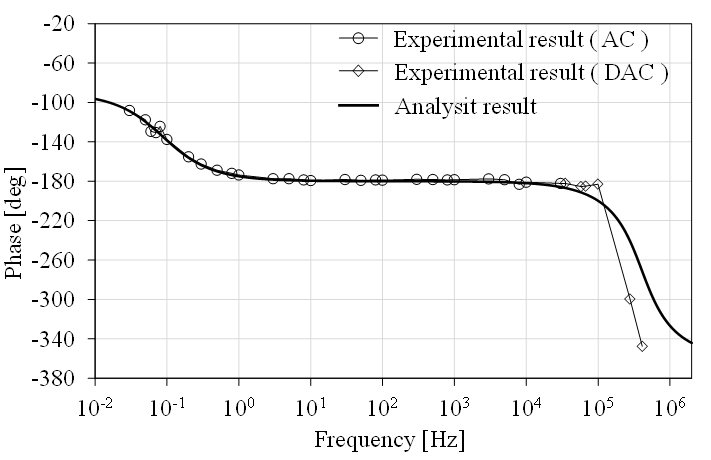
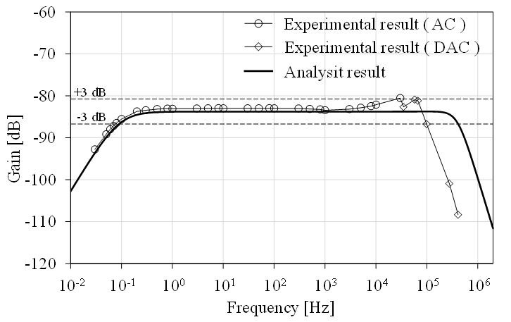
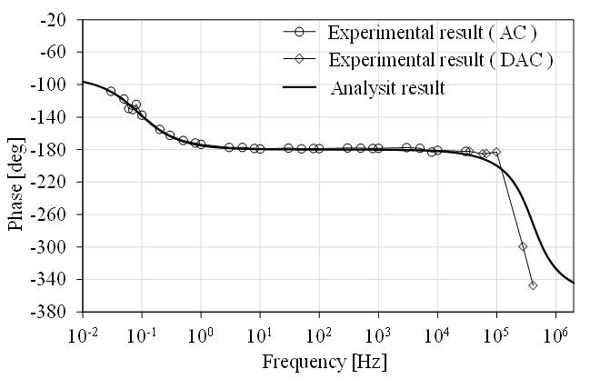
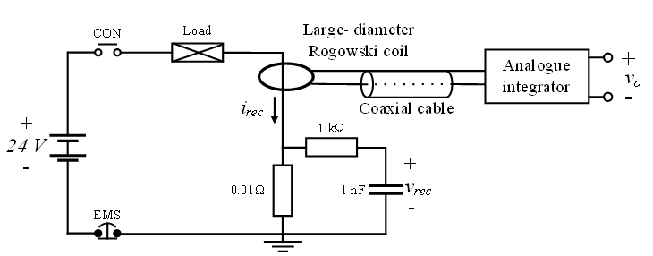
Frequency characteristic testing of LDS was divided into two ranges: below 30 kHz and above 30 kHz. The test schematic and actual test are depicted in Figure 8. Test results for gain and phase shift are shown in Figures 9 and 10, respectively. Analysis using (1) and test results are well aligned. For frequencies below 100 kHz, the MSE of gain and phase is 0.04 and 0.08, occurring at approximately 30 kHz and 100 kHz, respectively. At higher frequencies, the analog integrator components exhibit bandwidth limitations. However, these frequencies are beyond the range of interest and will not affect the LDS performance in practical use. The test details are as follows.
- LDS test at a frequency below 30 kHz, the test was conducted with its schematic and actual test configuration depicted in Figure 8, using AC voltage as a source. Input current and output voltage were measured to determine gain and phase shift.
LDS test at a frequency above 30 kHz, a relatively high current is required to assess frequency characteristics. To overcome this challenge, tests were conducted using damped alternating current (DAC), the waveform suggested as an alternative by the JEM standard [6].
4. LDS Low Cutoff Frequency Verification
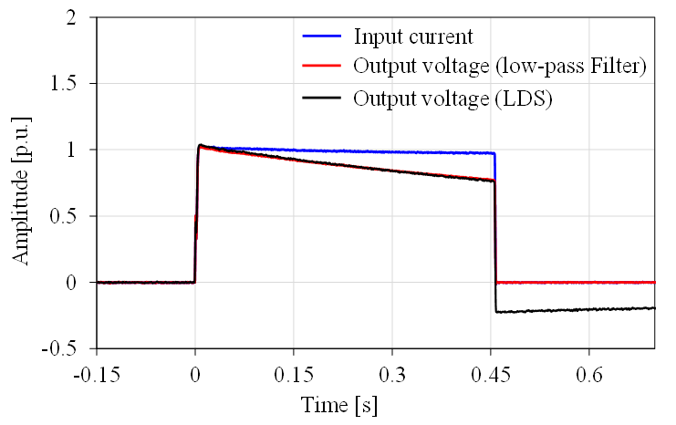
A low cutoff frequency of LDS is a crucial parameter as it directly impacts measurements of total charge. To verify the cutoff frequency, a rectangular pulse response of LDS is compared to that of a known low-pass filter with a specific cutoff frequency.
Due to its sharp transitions, a rectangular pulse contains a broad spectrum of sinusoidal frequencies. When applied to a low-pass filter, the flat top of the pulse gradually decays toward zero. The higher the cutoff frequency, the faster this decay occurs. To confirm the cutoff frequency of the LDC at 0.1 Hz, a first-order low-pass filter with a cutoff frequency of about 0.08 Hz was selected. The filter was composed of a 15 kΩ resistor and a 130 µF capacitor [21].
The test was conducted as schematic shown in Figure 11. The pulse had an amplitude of approximately 1000 A and a duration of 450 ms. The reference pulse response was obtained by replacing the LDS with the filter. Input current and output voltage were measured, and the results, shown in Figure 12, demonstrate good alignment for the time range of approximately 0 to 450 ms. This confirms that the LDS has a lower cutoff frequency of at least about 0.08 Hz, meeting the intended design specification of 0.1 Hz.
5. Conclusion
A lightning detection system for wind turbine applications is presented in this paper. The system consists of the large-diameter Rogowski coil and the analog integrator. It operates with a bandwidth range of 0.1 Hz to 100 kHz and a linear gain of approximately -83 dB. The developed large-dimeter Rogowski coil is designed with a diameter of 4 m, 1400 turns in total, and a slope of 20 dB/decade. The developed analog integrator has a slope gain of -20 dB/decade and consists of the inverting active integrator and an amplifier.
A series of tests were conducted to assess the frequency characteristics of the LDS, particularly the lower and upper cutoff frequencies. LDS frequency characteristics were measured using alternating current (AC) for frequencies below 30 kHz and damped alternating current (DAC) for higher frequencies. The results align well with the analysis, with a maximum gain error of less than 3 dB, confirming the upper cutoff frequency to be 100 kHz. Additionally, the lower cutoff frequency of the LDS was verified using a rectangular pulse response, confirming that it is lower than 0.1 Hz.
The developed LDS complies with the standard required bandwidth while offering significant cost-effectiveness compared to commercial alternatives. This makes the LDS suitable for field applications in lightning detection for wind turbines.
Acknowledgment
Authors would like to give special acknowledgment to High Voltage Laboratory, Graduate School of Electrical and Electronic Engineering, Chubu University for the support and facilities.
- Council, Global Wind Energy. “GWEC global wind report 2019.” Global wind energy council: Bonn, Germany (2017).
- Council, Global Wind Energy. “GWEC global wind report 2024.” Global wind energy council: Brussels, Belgium (2024).
- Cummins, K. L. “Overview of the Kansas Windfarm 2013 Field Program, 23rd Intl.” In Lightning Detection Conference, Vaisala, Tucson, AZ. 2014.
- Wang, D., N. Takagi, T. Watanabe, H. Sakurano, and M. Hashimoto. “Observed characteristics of upward leaders that are initiated from a windmill and its lightning protection tower.” Geophysical research letters 35, no. 2 (2008).
- Ishii, Masaru, Mikihisa Saito, Masaaki Chihara, and Daisuke Natsuno. “Transferred charge and specific energy associated with lightning hitting wind turbines in Japan.” IEEJ Transactions on Power and Energy 132, no. 3 (2012): 294-295.
- Lightning current detection-Part, New Power Generation System. “1515: Test methods of Lightning current detection system for wind turbines.” The Japan Electrical Manufactures’ association, JEM (2023): 1515.
- Turbines-Part, Wind. “24: Lightning protection.” International Electrotechnical Commission, IEC (2010): 61400-24.
- Rogowski, Walter, and Wilhelm Steinhaus. “Die messung der magnetischen spannung.” Electrical Engineering (Archiv fur Elektrotechnik) 1, no. 4 (1912): 141-150.
- Transformers-Part, Instrument. “10: Lightning protection.” International Electrotechnical Commission, IEC (2017): 61869-10.
- Liu, Yi, Fuchang Lin, Qin Zhang, and Heqing Zhong. “Design and construction of a Rogowski coil for measuring wide pulsed current.” IEEE Sensors Journal 11, no. 1 (2010): 123-130.
- Li, Weibo, Chengxiong Mao, and Jiming Lu. “Study of the virtual instrumentation applied to measure pulsed heavy currents.” IEEE transactions on instrumentation and measurement 54, no. 1 (2005): 284-288.
- Robles, G., M. Argueso, J. Sanz, R. Giannetti, and Bernardo Tellini. “Identification of parameters in a Rogowski coil used for the measurement of partial discharges.” In 2007 IEEE Instrumentation & Measurement Technology Conference IMTC 2007, pp. 1-4. IEEE, 2007.
- Hlavacek, Jan, Radek Prochazka, Karel Draxler, and Vladislav Kvasnicka. “The Rogowski coil design software.” In Proc. 16th IMEKO TC4 Int. Symp, pp. 295-300. 2008.
- Xiang, Minjiang, Houlei Gao, Baoguang Zhao, Chengzhang Wang, and Chun Tian. “Analysis on transfer characteristics of Rogowski coil transducer to travelling wave.” In 2011 International Conference on Advanced Power System Automation and Protection, vol. 2, pp. 1056-1059. IEEE, 2011.
- Rezaee, Morteza, and Hossein Heydari. “Mutual inductances comparison in Rogowski coil with circular and rectangular cross-sections and its improvement.” In 2008 3rd IEEE Conference on Industrial Electronics and Applications, pp. 1507-1511. IEEE, 2008.
- Limcharoen, Worrakan, and Peerawut Yutthagowith. “Rogowski coil with an active integrator for measurement of switching impulse current.” In 2013 10th International Conference on Electrical Engineering/Electronics, Computer, Telecommunications and Information Technology, pp. 1-4. IEEE, 2013.
- Wang, Baocheng, Deyu Wang, and Weiyang Wu. “A Rogowski coil current transducer designed for wide bandwidth current pulse measurement.” In 2009 IEEE 6th International Power Electronics and Motion Control Conference, pp. 1246-1249. IEEE, 2009.
- Ogata, Katsuhiko. Modern Control Engineering. United Kingdom: Prentice Hall, 2010.
- Alexander, Charles K., Matthew NO Sadiku, and Matthew Sadiku. Fundamentals of electric circuits. Boston, MA, USA: McGraw-Hill Higher Education, 2007.
- Hoffman, Joe D., and Steven Frankel. Numerical methods for engineers and scientists. CRC press, 2018.
- Chattopadhyay, D., and P. C. Rakshit. Fundamentals of Electric Circuit Theory. S. Chand Publishing, 2000.
No related articles were found.