Modeling and Control of Collaborative Robot System using Haptic Feedback

Adv. Sci. Technol. Eng. Syst. J. 2(3), 1549–1555 (2017);
 DOI: 10.25046/aj0203193
When two robot systems can share understanding using any agreed knowledge, within the constraints of the system’s communication protocol, the approach may lead to a common improvement. This has persuaded numerous new research inquiries in human-robot collaboration. We have built up a framework prepared to do independent following and performing table-best protest object manipulation with humans and we have actualized two different activity models to trigger robot activities. The idea here is to explore collaborative systems and to build up a plan for them to work in a collaborative environment which has many benefits to a single more complex system. In the paper, two robots that cooperate among themselves are constructed. The participation linking the two robotic arms, the torque required and parameters are analyzed. Thus the purpose of this paper is to demonstrate a modular robot system which can serve as a base on aspects of robotics in collaborative robots using haptics.
1. Introduction
The Perception of robot motions is really important. In recent years, there has been in increasing interest in distributed robotic systems. In such a system, a task is not completed by a single robot but instead by a team of collaborating robots. Team members may exchange sensor information, may help each other to scale obstacles, or may collaborate to manipulate heavy objects. A team of robots has distinct advantages over single robots with respect to actuation as well as sensing. When manipulating or carrying large objects, the load can be distributed over several robots so that each robot can be built much smaller, lighter, and less expensive. As for sensing, a team of robots can perceive its environment from multiple disparate viewpoints. A single robot, on the other hand, can only sense its environment from a single viewpoint, even when it is equipped with a large array of different sensing modalities. There are many tasks for which distributed viewpoints are advantageous: surveillance, monitoring, demining, plume detection, etc.
Comparing the motions of a robot is very censorious activity. Elaborating some motions may be arduous as the operator should manage the overall motion; for example, these questions include: “ The robots which are designed are with respect to the environment. Will the robot work with the same efficiency?”, “Is the operator getting the same outcome?”, “Are the motions of the robot constrained to specified trajectories?”, “Will both the geometric specifications of the path as well as the velocity at which the robot traverses the path be followed?, “What are the control issues in the robotic control?” or “What are the fundamental problems in mobile robotics?”The word “cobot”. “Co” stands for “collaborative”. We can find it in “co-working”, “co-design”, “co-development”, and the list goes on. Work together, find better solutions together, and produce faster together. Here’s the idea. Together. With new technologies coming up fast and better ways of communication, people and companies start to handle resources and skills in a better way. Make people work in open spaces, encourage them to interact with different background and culture individuals, try new flexible organization processes, are parts of this new collaborative mind. The idea is simple: work smarter together for better results. Cobots can have many roles — from autonomous robots capable of working together with humans in an office environment that can ask you for help, to industrial robots having their protective guards removed as they can react to a human presence under EN ISO 10218 or RSA BSR/T15.1.
When two robot systems can share understanding using any agreed knowledge, within the constraints of the system’s communication protocol, the approach may lead to a common improvement. This has persuaded numerous new research inquiries in human-robot collaboration. We have build up a framework prepared to do independently following and performing table-best protest object manipulation with humans and we actualize two different activity models to trigger robot activities. The idea here is to explore collaborative systems and to build up a plan for them to work in a collaborative environment which has many benefits to a single more complex system. In the paper, two robots that cooperate among themselves are constructed. The participation linking the two robotic arms, the torque required and parameters are analyzed. Thus the purpose of this paper is to demonstrate a modular robot system which can serve as a base on aspects of robotics in collaborative robots using haptics. The primary aim is to design an actively articulated robotic arm and dynamically control its orientations i.e. yaw, pitch and roll using negative feedback to assure stability or the desired orientation at all times.
The collaborative robots seen so far are based on hard coding and are run with respect to each other. This barrier may create some issue during the interaction of the robot like if the time gives to robotic arm is different than the other after several cycles the robot will stop working in a synchronize mode and could create a problem. We are planning to an interactive platform that could create not only human-robot interaction as well as robot-robot interaction. This could reduce the barrier and could work in synchronized mode. Even we are able to make the system open source that it could be used by the college student and work on the background rather working on the fabrication part. We are using detailed simulation software only for the simulation, so the student could work on the developed CAD model to test the respective operation without direct using the provided hardware. This could reduce the risk of damage to the fabricated hardware.
2. Literature Review
In the previous paper [1], we had introduced how autonomous robots would benefit from improvements in haptic intelligence and overview of telerobotics systems. In the real world, we want robots to help to perform tasks in the remote environment. We have demonstrated the design and manufacture of a touch robotic arm that is inspired by a motive to increase efficiency. A multi-robot system can investigate an unknown domain speedier than a single robot system, even with the imperative of performing meeting to permit correspondence. In [2], the author has demonstrated the issue of how two heterogeneous robots can mastermind to meet in an obscure domain from obscure beginning areas. In [3], the author has ideated another approach for two-sided control in delta robot which has been proposed so as to lessen gravity impact [4]. In [5], [6], the author portrays the advancement of automated innovations that empower another vision of shared versatile assembling by groups of robots. In [7], the author. concentrates on the improvement and combination of the sensor arm used to convey a spectrometer from a multi-meter scale robot to centimeter scale rocks. The sensor arm joins off the rack equipment for movement control, activation, and detection. In [8], the author has tended to the inquiries of whether and when a robot ought to step up with regards to joint human-robot undertaking execution by contrasting three activity models with trigger robot activities: human-started help, robot-started receptive help, and robot started proactive offer assistance. In [8], [9], the author has clarified a review on participation between two master-slave modular robots in the paper. Kinematics of the system is contemplated. A tri-dimensional estimation arrangement of Optotrak 3020 is utilized to input the end position of the two robots. He tended to [9] the undertaking of organizing the movements of different controllers when either their directions or their ways are given. By exploiting a principal time scaling law for controllers in light of their elements, we distinguish adequate conditions for crash free coordination of the robots when the velocity profiles can be consistently time-scaled and the robot begins times can differ. [10] The demonstration of the transportation of numerous things to stations that make ask. The collaborative collection technique can outperform the individual accumulation strategy with up to 15.4% diminishment in maximum traveling cost. At that point [11] proposed scientific models for these surmisings in view of streamlining cost, attracting the similarity to the guideline of objective activity. In [12] and [13], the respective authors presented a robot control system which has been particularly intended for a subjective robot which offers space and undertaking with a human. The approach is productive in light of successful individual and collective abilities. In [14], the author looked into tactile sensing applications incapable robot hand control. The fundamental sorts of material sensors and their reconciliation with robot hands are discussed. Tactile data processing techniques and its applications are displayed.
3. Design
3.1. Specifications
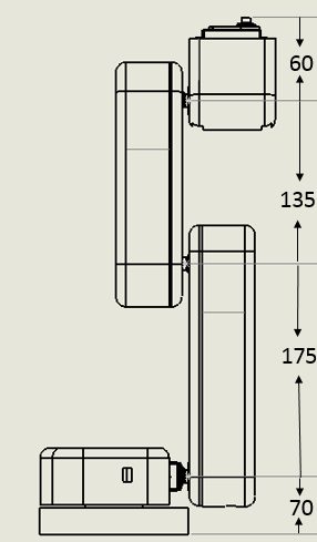 Figure 1: Robotic Arm Structure (dimensions in mm)
Table 1: Specifications of Robotic Arm
| Sr. No. | Parameters | Specification |
| 1 | DOF | 5 axes |
| 2 | L1 | 175mm |
| 3 | L2 | 135mm |
| 4 | L3 | 60mm |
| 5 | Height | 440mm |
| 6 | Joint-1 | 180 degrees |
| 7 | Joint-2 | 180 degrees |
| 8 | Joint-3 | 180 degrees |
| 9 | Joint-4 | 180 degrees |
| 10 | Joint-5 | 180 degrees |
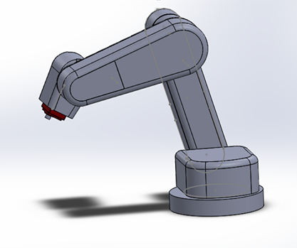 Figure 2: The redefined robot imported from the 3 D model into Solidworks model.
The aim was to build a collaborative robot system that could work with a single control unit. The primary aim was to develop a single system that could help the robot to communicate with each other and work together. There are five degrees of freedom (DOF) robotic arm. The entire robotic system was designed in Solidworks and manufactured using 3D printing process. The goal was to make the control system which could be easily operated and understood by the operator. A robot with the same dimension that is going to be manufactured is imported in the V-REP software. In this method, the robot is made to follow defined paths that are plotted using path planning function. The robot is programmed to follow the plotted path. Inverse kinematics helps the robot to follow the specified path. Individual joints calibrate their own angle and the end effector tries to reach the defined path. While following the path the robot joint angle values differ from joint to joint. Absolute joint values are obtained in V-REP during operation and even the XYZ values of the end effectors can be generated.
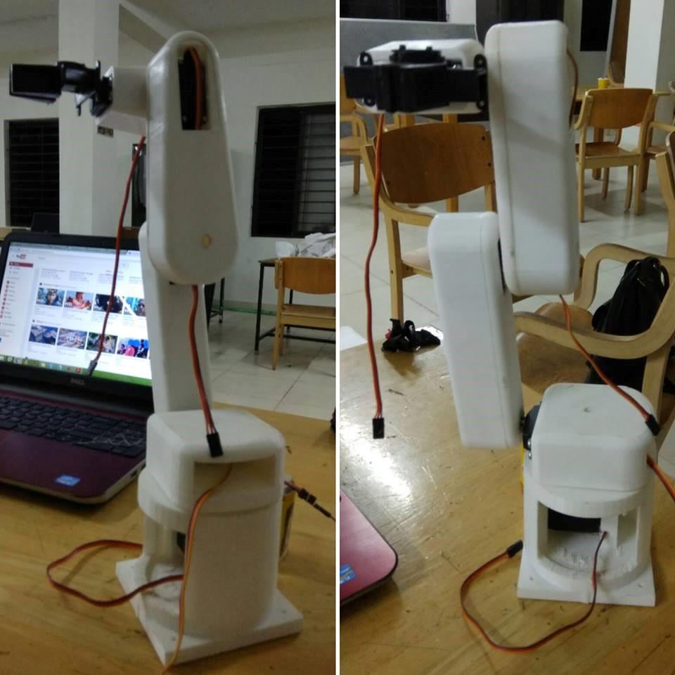 Figure 3: 3D printed Hardware model
4. Math
4.1. DH Parameters
The 5-DOF manipulator kinematic parameters are derived using Denavit Hartemberg formulation:
% theta d a alpha
L (1) = Link ([q 70 -22.2 -pi/2 0]);
L (2) = Link ([q -70.0 175 pi 0]);
L (3) = Link ([q -4.0 135 0 0]);
L (4) = Link ([q 0.1 60 pi/2 0]);
L (5) = Link ([q 0.80 0 pi 0]);
L (6) = Link ([gripper 0]);
All measurements are in centimeters.
q0 =[0 -pi/3 -pi/3 pi/2 0 0 ];
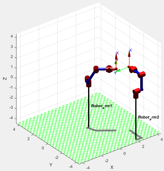 Figure 4: Sequential Robot movements of the Collaborative robotic arms for the required path.
The workspace of the end-effector relies on upon the physical furthest reaches of the five joints point, i.e. on the off chance that the point scope of the robotic arm joints is changed the workspace of the robot changes. So it is critical to consider the precision in deciding the edge scope of the robot joints to get the required workspace which covers the working range.
The general form of the Homogeneous Transformation Matrix is:
[cos(q) -cos(a)*sin(q) sin(a)*sin(q) A*cos(q)
sin(q) cos(a)*cos(q) -sin(a)*cos(q) A*sin(q)
0 sin(a) cos(a) d
0 0 0 1 ]
A1 = [ 1.0000 0 0 -22.2000
0 0.0000 1.0000 0
0 -1.0000 0.0000 70.0000
0 0 0 1.0000 ]
A2 = [0.5000 -0.8660 -0.0000 87.5000
-0.8660 -0.5000 -0.0000 -151.5544
0 0.0000 -1.0000 -70.0000
0 0 0 1.0000]
A3 = [0.5000 0.8660 0 67.5000
-0.8660 0.5000 0 -116.9134
0 0 1.0000 -4.0000
0 0 0 1.0000]
A4 = [0.0000 -0.0000 1.0000 0.0000
1.0000 0.0000 -0.0000 60.0000
0 1.0000 0.0000 0.1000
0 0 0 1.0000]
A5 =[1.0000 0 0 0
0 -1.0000 -0.0000 0
0 0.0000 -1.0000 0.8000
0 0 0 1.0000]
The link transformations matrix can be given as:
0T5 = A1*A2*A3*A4*A5
0T5= [0.0000 0.0000 -1.0000 201.0970
0 1.0000 0.0000 -66.1000
1.0000 -0.0000 0.0000 281.5501
0 0 0 1.0000]
4.2. Working
The flowchart representing the sequence of generating the CODE of the link transformations matrix is shown in Figure 5.
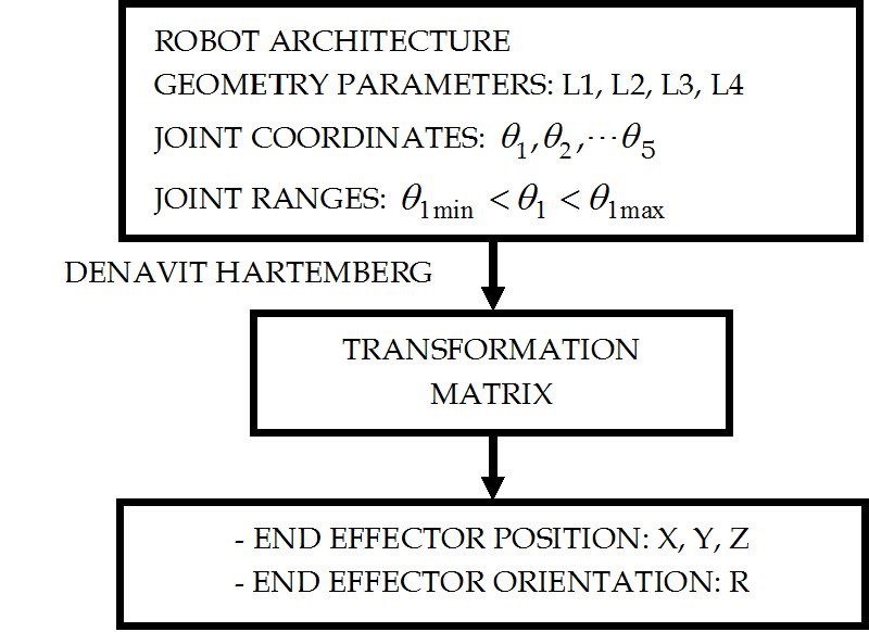 Figure 5: The flow chart of link transformation matrix.
There are four distinct strategies which are derived from figuring the direction arranging of the robot utilizing the code. The direction planning in the four techniques requires two parameters, specifically the joint point run and the last time required to finish the procedure. The first was chosen from the workspace expected to finish the procedure. For any situation, this subject to the sort of surgical applications and can without much of a stretch be distinguished. The final time needed is a vital parameter to determine the trajectory of the robotic arm. As every one of the outcomes that have been construed from the introduction, acceleration speed and torque of the robotic arm depend on this parameter. In the event that the time expands the speed needed declines and increasing speed i.e. the inertia of the arm connect therefore diminishes unintentionally regardless of the techniques utilized. The introduction must be seen precisely inspected and the conduct ought to increment step by step with the time from the underlying edge to the final point. The final time needed to finish the procedure for every technique ought to be improved and this is referred to as optimal planning. In this study, the trajectory planning has been derived and after that, correlation of the outcomes a particular joint is made. The best possible time which gives tasteful outcomes is obtained.
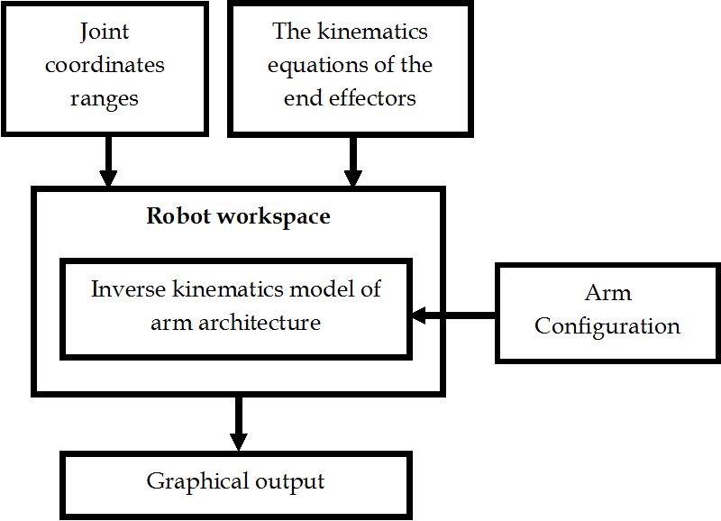 Figure 6: The flowchart for Robot workspace.
4.3. Electronics
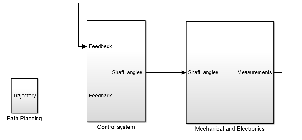 Figure 7: Simulink model of the Robot System.
These Simulink models are created in MATLAB using the robotics toolbox. The mechanical and electronic system contains the hardware as well as the electronics part. In this, the electronic components are the motors. The amount of rotation is given by the control system with the means of shaft angle. This shaft angle is provided by the robotics toolbox blocks. The motor tries to achieve the given shaft angle and provides the feedback to the control system. Then the control system provides the proper angle again reducing the error. The path planning is done and as shown in Figure 7 and the robot tries to move with respect to it. These types of feedback make the robot to easily achieve the respective position.
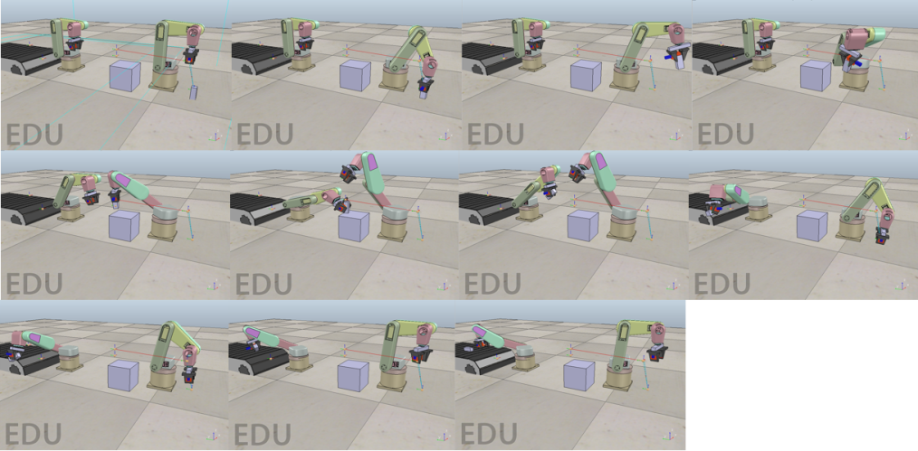 Figure 8: Coordination of Robotic arm in V-REP obatined from importing simulink model.
There are two lines appeared in the Figure 9. The blue one informs the movement of the end effector joint for the Robot arm 1 and the other line notifies the movement of Robot arm 2 regarding the z-axis. The movement of both the end effectors as for z-axis and time. The simulation done was the sample study of pick and place for corporative manipulators. As shown in the graph the robot one end effector moves with respect to z-axis move down practically to ground level. The robot tries to pick the object and remains there for 20 seconds. The robot picks the object and move to the upper level and move linearly in the XY plane. The robot achieves a specific position and the other robot arm which was very still going to a same position of the Robot arm1 yet the other robot is at a lower level to get the object and proceed with the cycle. As the robot arm1 drops the question from the gripper the haptic feedback recognizes the other robot and makes the other robot to get the object as the Robot arm 2 end effector is at a similar z-axis. The Robot arm 2 completes the movement. In this system, one robot arm communicates with the other robot arm with the sensing of the gripped object in the end effector as the object from the gripper tries to slip the other robot gripper tries to hold the object.
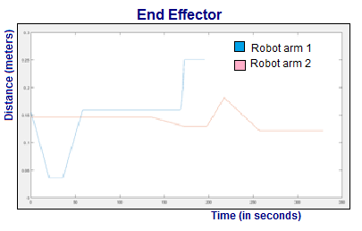 Figure 9: Position control of end effector with respect to z-axis. X axis is time in seconds and Y axis is distance in meters.
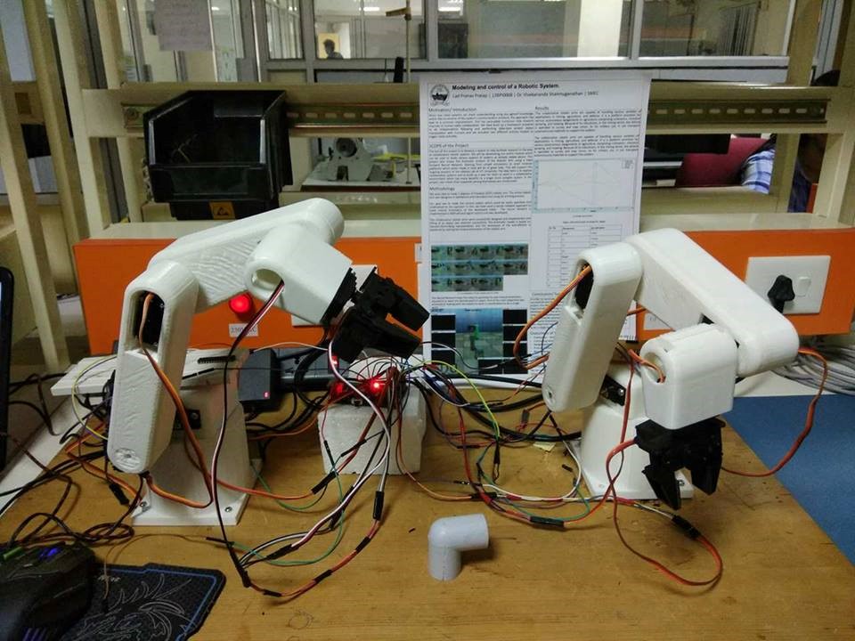 Figure 10: Hardware model of Robot System.
In order to conclude about the project execution, the project was carried out successfully and the desired output was obtained. Talking specifically about the project, the development of two robotic arms was successfully done and our main objective about making a single brain that could command both the arm was developed. Both the arms receive a command decently and behave as a single system.
4.4. Force Sensitive Resistor for Haptic Feedback
A force-sensing resistor is a material whose resistance changes when a force or pressure is applied. Figure 10 shows a demonstration of how to construct an Arduino-based pressure sensor that displays the measured pressure on a small LCD screen. With a minor adjustment to the code, one can just read the FSR values in the Arduino serial window. In that case, none of the LCD/potentiometer stuff is needed. Force Sensing Resistors (FSR) is a polymer thick film (PTF) device which exhibits a decrease in resistance with an increase in the force applied to the active surface. Its force sensitivity is optimized for use in human touch control of electronic devices. With a minor adjustment to the code, one can just read the FSR values in the Arduino serial window. In that case, none of the LCD/potentiometers is needed. The Force Sensitive Resistor (FSR) with a sensing area of 0.5” diameter is attached to the gripper. The sensor uses a voltage divider. The FSRs get a 10k resistor, and the flex resistor gets a 22k resistor. The voltage divider works with the changing resistance of the sensors. When the resistance is higher for the variable resistor, there is a larger voltage drop across the variable resistor. The voltage dividers are supplied with +5V, and that drop in 5V is split between the two resistors. The Arduino measures the voltage between the resistors and returns value between 0 and 1023 based on the voltage reading (0 being 0V and 1023 being 5V).
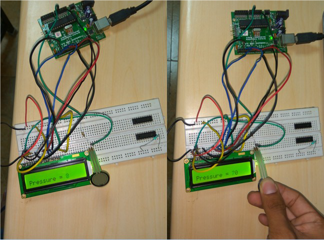 Figure 11: Display variance in pressure.
Figure 11 shows the interface of FSR with MATLAB. This figure demonstrates the calibration of a Force Sensitive Resistor (FSR) using the Arduino UNO board and MATLAB. Additionally, the UNO board logs real-time FSR data. The input and output data is as follows:
Force: [133g 175g 185g 250g 490g]
Voltage 1= [0.3955 1.0693 0.69 1.2793 1.330]
Voltage 2= [0.48 0.87 1.82 1.29 1.48]
Voltage 3= [0.65 0.94 1.015 1.15 1.41]
Average voltage= [0.5085 0.9597 1.048 1.406]
Therefore, plot between Force and Voltage:
Force_Xaxis= [133,175,183,250,490]
Voltage_Yaxis= [0.5085,0.9597,1.048,1.2397,1.406]
The Linear model Polynomial equation:
J(x) =Ax3+Bx2+Cx+D where, A=1.562x 10⁻⁷
B=-0.000152
C=0.04677
D=-3.391
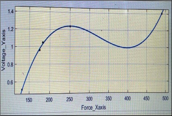 Figure 12: Interface of FSR with MATLAB
5. Results and Discussion
Through the processes of conceptualization, design, assembly, and final coding, we were required to complete tasks ranging from needs assessment, static and dynamic load analyses, design for manufacturing, machining, troubleshooting, and finally microcontroller coding, to name but a few. Therefore following the earlier paper we studied human-machine interaction and works in a similar way as the body goes in specific direction or manner and shows sensation at the same time. The collaborative robotic arms were successfully designed and implemented and lifting of an object was attained successfully. The kinematic model is based on Denavit-Hartenberg representation and the workspace of the end-effector is explained by solving the inverse kinematics of the robotic arm. It plainly appeared in this work the best technique for trajectory planning that gives the smooth set trajectory planning and best execution of the robotic arms under examination was the delicate movement trajectory planning on the grounds that the most vital explanation behind this choice was the torque history that has the least number ever of shooting and the shooting was dispersed frequently over the timeframe, unlike alternate strategies which have a long number of shootings and were circulated arbitrarily.
The collaborative robotic arms are capable of handling various varieties of applications in mining, agriculture, and defense. It is a platform provision for various autonomous assignments in agriculture comprising cultivation, chemical spraying, and mowing. Because of its robustness, in the mining sector, the vehicle is operated to survey and map mines. As for military use, it can transport autonomously materials to support the soldiers. This paper also accentuates the synergy between the human operator and a robot and has various applications in healthcare, medicines, entertainment, education, graphic arts, the industry as well as space. A high level of precision was observed in the movement of the robotic arm due to the generation of accurate control signals for the servo motors. In collaboration with the visual display, haptics can be exploited by people for tasks involving hand-eye coordination, essentially Space-ship maneuvering, and Robotic Tele- Surgery. It can also be used for games in which you feel and at the same time see your Interactions with images. The information regarding the different touch forces supports the approximation of the contact accomplished by the sensor mounted on the gripper and permit the experiencing the slipping of an object.
6. Future Work
The machine learning calculations enhance and different advances, for example, neuromorphic chips, empower more brilliant robots, we’ll be seeing them do tasks that no one but people can do until now, with the exception of, by and large, they will have the capacity to improve. They will have the capacity to get to incomprehensible databases, perceive individuals, machines and parts, have the capacity to determine bits of knowledge and follow up on them. That implies that robots will soon have the capacity to do short work, as well as analyze issues and devise arrangements. They’ll have the capacity to do schedule, highly monotonous work like the quality affirmation, assessing parts and completed items. Likewise, the cost of all that capacity will probably descend significantly as innovation advances and the cost of parts decreases.
- Mansi Pawar, Pranav Lad,”Development of robotic arm using haptic feedback”, IEEE International Symposium on Robotics and Manufacturing Automation(ROMA), Year 2016, Pages 1-7. DOI: 10.1109/ROMA.2016.7847815.
- Nicholas Roy, Gregory Dudek, “Collaborative Robot Exploration and Rendezvous: Algorithms, Performance Bounds and Observations”, Autonomous Robots, September 2001, Volume 11, Issue 2, pp 117–136.
- Chowarait Mitsantisuk, Kiyoshi Ohishi, “Haptic human-robot collaboration system based on delta robot with gravity compensation”, IECON 2016 – 42nd Annual Conference of the IEEE Industrial Electronics Society, Year: 2016, Pages: 5796 – 5801.
- Glenn Wagner , Minsu Kang, and Howie Choset, “Probabilistic path planning for multiple robots with subdimensional expansion”, IEEE International Conference on Robotics and Automation (ICRA), , May, 2012, pp. 2886–2892.
- David Bourne, Howie Choset, Humphrey Hu, George A. Kantor, Christopher Niessl, Zack Rubinstein, Reid Simmons, and Stephen Smith, “Mobile Manufacturing of Large Structures”, Proceedings 2015 IEEE International Conference on Robotics and Automation, May, 2015.
- Christopher Urmson, Benjamin Shamah, James Teza, Michael D. Wagner , Dimitrios (Dimi) Apostolopoulos , and William (Red) L. Whittaker,” A Sensor Arm for Robotic Antarctic Meteorite Search”, Proceedings of the 3rd International Conference on Field and Service Robotics, July, 2001.
- Jimmy Baraglia; Maya Cakmak; Yukie Nagai; Rajesh Rao; Minoru Asada,“Initiative in robot assistance during collaborative task execution”, 2016 11th ACM/IEEE International Conference on Human-Robot Interaction (HRI), Year: 2016, Pages: 67 – 74.
- Liying Su, Lei Shi, Yueqing Yu, Qixiao Xia, “Bolt and Screw Assemblage through Collaborative Kinematics Operation of Two Modular Robots Based on the Position Feedback”, Proceedings of the 2009 IEEE International Conference on Information and Automation, Pages: 1574 – 1579.
- S. Akella; S. Hutchinson, “Coordinating the motions of multiple robots with specified trajectories”. Proceedings 2002 IEEE International Conference on Robotics and Automation (Cat. No.02CH37292), Year: 2002, Volume: 1, Pages: 624 – 631 vol.1.
- S. Akella; Jufeng Peng, “Time-scaled coordination of multiple manipulation”, Robotics and Automation, 2004. Proceedings. ICRA ’04. 2004 IEEE International Conference on Year: 2004, Volume: 4, Pages: 3337 – 3344.
- Nantawat Pinkam; François Bonnet; Nak Young Chong, “Robot collaboration in warehouse”, 2016 16th International Conference on Control, Automation and Systems (ICCAS), Year: 2016, Pages: 269 – 272.
- Anca D. Dragan; Kenton C. T. Lee; Siddhartha S. Srinivasa, “Legibility and predictability of robot motion”, 2013 8th ACM/IEEE International Conference on Human-Robot Interaction (HRI), Year: 2013, Pages: 301 – 308.
- Felix Jimenez; Masayoshi Kanoh; Tomohiro Yoshikawa; Takeshi Furuhashi, “Effect of collaborative learning with robot that prompts constructive interaction”, 2014 IEEE International Conference on Systems, Man, and Cybernetics (SMC), Year: 2014, Pages: 2983 – 2988.
- Rachid Alami, “On human models for collaborative robots”,2013 International Conference on Collaboration Technologies and Systems (CTS), Year: 2013, Pages: 191 – 194.
- Zhanat Kappassova, Juan-Antonio Corralesb, Véronique Perdereaua, “Tactile sensing in dexterous robot hands — Review”, Volume 74, Part A, December 2015, Pages 195–220.