Indoor Mobile Robot Navigation in Unknown Environment Using Fuzzy Logic Based Behaviors

Adv. Sci. Technol. Eng. Syst. J. 2(3), 327–337 (2017);
 DOI: 10.25046/aj020342
This paper presents the development and design of a methodology based on fuzzy logic to control an indoor mobile robot for a complete navigation in an unknown environment. The methodology incorporates two basic behaviors, namely: reaching the goal and avoiding obstacles. The obstacle avoidance behavior is treated using wall-following scheme based on an Interval Type-2 Fuzzy Inference technique. .This helps in handling data uncertainties to produce a better performance. The mobile robot control mechanism uses some sort of knowledge base arranged in a set of fuzzy-rule-base to implement the wanted behavior that makes the mobile robot follow the boundary of an obstacle or a wall. A constant distance to the obstacle/wall is maintained while the robot tries successfully to get around this difficulty. Once the path is clear, the obstacle avoidance behavior is inhibited and reaching the goal behavior is activated using a secondary fuzzy controller. This methodology was successfully tested on a real mobile robot for different sort of scenarios. In order to provide better insight into the work’s objective, a comparison work with another method, which uses a Partial Swarm Optimization-Fuzzy method, is carried out based on some defined criteria. The experiment shows a better improvement in the results of the proposed method.
1. Introduction
Mobile robots have a special place in robotics. Their interest lies in their mobility, which covers applications in many fields (nuclear, navy, space, firefighting, surveillance, load transportation …). The particular aspect of mobility requires a methodological and technological complexity that adds to the general problems faced by mobile robots. Solving these problems requires the use of all available resources both in technology (sensors, motor, and energy) and in information processing by using artificial intelligence techniques or special processors. The autonomy of a mobile robot is a faculty, which enables it to adapt or make a decision in order to perform a task despite a lack of preliminary or possibly erroneous information. In other cases, such as vehicle exploration of planets [1], garbage collector [2], foraging [3], autonomy is a fundamental issue because remote control is impossible due to the propagation delay. The main focus of such research directions is how to let a mobile robotic body navigate in an unstructured environment without collisions; and how to combine these two behaviors in order to achieve the required robot tasks. In fact, if we arrive to control the robot to achieve the first behavior, it would be a difficult task for the robot to navigate in a cluttered environment. One of the solutions which has been an interesting research topic over the past few years is wall following. This behavior is one of the multi-issues that can be used to avoid obstacles. In fact, the robot moves along the object while keeping a certain safe distance. This behavior may be used to follow a real wall, concave or convex objects, and labyrinths. Wall-following strategy could be very helpful when the mobile robot is being trapped in deadlocks caused by local minima. Despite the number of publications appeared in this field of research, mobile robot navigation is still considered as a topic of extensive research.
Many papers have dealt with the topic of mobile robot navigation using different approaches. Conventional approaches have limitations and cannot respond optimally to non-linear dynamics and the change of system parameters. In the literature, one can find new approaches based on artificial intelligence developed to cope with these limitations and fuzzy logic theory was used extensively for this purpose [4]. The obstacle avoidance problem is also considered as a challenge when designing an autonomous mobile robot, and this issue has been tackled using many approaches [5]. On the other hand, signals captured by sensors, when an obstacle is detected, are contaminated with noise from different sources and probably associated with other unwanted signals. Therefore, the problem of detecting the obstacles and positioning its emplacement poses the problem of uncertainties, precision and accuracy. In this case, new control methods based on artificial intelligence, such as fuzzy logic, were introduced. Liu et al [6] analyzed the relationship between the motion characteristics and installation position of sensors of mobile robots and proposed a self-convergence mathematical model. The purpose of their work is to execute the wall-following activity with only a single distance proximity switch. Based on a spiking neural network controller, Wang et al. [7] used sonar sensory readings to guide their mobile robot to follow the wall. The idea of using fuzzy rules to implement a wall-following-based obstacle controller has been proposed in [8], a fuzzy system based on the concept of general perception was proposed to control the mobile robot navigating along walls of arbitrary shape and around obstacles. The autonomous mobile robot (MR) in [9] is equipped with two IR proximity sensors. The wall following is based merely on sensorial information given by these two IR sensors. In order to improve noise resistance ability, some researchers applied control laws based on interval type-2 fuzzy logic [10-13]. Hsu et al, [10] proposed an evolutionary wall-following control of a mobile robot using an interval type-2 fuzzy controller with Species-Differential-Evolution activated Continuous Ant Colony Optimization (SDE-CACO). All fuzzy rules are generated online using a clustering-based approach during the evolutionary learning process. . Other works investigates a control based on Inverted Ant System IAS, such as [4] and other investigated Cellular Automata and Inverted Ant System to control a swarm of robots in foraging task [3]. The control and other aspects implementation, such as, coordination and synchronization are described in [11]. An interesting work has been proposed in [14], where the authors suggested a reinforcement and optimized fuzzy controller method for mobile robot wall following. The method was successfully tested on the mobile robot Pioneer 3-DX. However, the methodology requires a learning procedure, which requires gathering data and a lot of computation time.
This paper proposes a new fuzzy logic methodology to control an indoor mobile robot for a complete navigation in an unknown environment. This methodology is based on two basic behaviors, reaching-the-goal while avoiding unforeseen obstacles. The two behaviors are designed using fuzzy logic tools inspired from human capacity reasoning with perception-based information. Type-1 fuzzy sets are precise but unable to handle data uncertainties. To incorporate these uncertainties, we need to make an extension. The idea is to consider the membership grade of an element to be a fuzzy set of type-1 rather than a number within the interval [0 1]. In this work, we propose a new scheme for obstacle avoidance based on wall following and to our knowledge, the manner we used in getting around the obstacle by partitioning the obstacle-near-region into three regions has not been used before. The mobile robot is equipped with US sensors that provide range reading, determining the distances between the robot and the obstacle. The inputs characterizing the information on the environment are fuzzified and presented to the inference engine for generating control outputs. The interesting part in this work is the way the obstacle avoidance using wall following is treated. This methodology, up to the author’s knowledge, offers a new idea of tackling this problem when the obstacle neighborhood is divided into three regions. For each region, a linguistic fuzzy rule based system is defined.
2. The proposed general navigation problem
The complete navigation problem has to deal with two important different behaviors. The main behavior is to reach the goal starting from any initial robot configuration. The second behavior is the mobile robot ability to avoid obstacles. Given these two behaviors, we should find a way to combine them in order for the mobile robot to execute the given mission successfully. In this case, one can either build a mode that switches between the two behaviors or have a blended action that combines between the two. Switching between the two behaviors can guaranty the success of the mission. However, the rapidly transitions between these two behaviors might result in a non-practical or a non-feasible action. On the other hand, the blended behavior might result in a smooth action. However, it does not guaranty the success of the task. One solution consists of weighting these two actions in order to successfully achieving the mission. Given the fact that the real world is composed of convex and concave obstacles, walls, labyrinths, etc., we need to elaborate a control action that guides the mobile robot along the obstacle boundaries toward its final destination. To detect the obstacles, we make use of the ultrasonic or infrared sensors that are provided with the wheeled mobile robot Khepera developed at the LAMI laboratory, Lauzane Switzerland.
Khepera is an automated differential drive guided vehicle specially designed and equipped for autonomous navigation utilized in many research laboratories. The execution of the task is related to the two-evocated main behaviors:
- Reaching the goal
- Avoiding obstacles
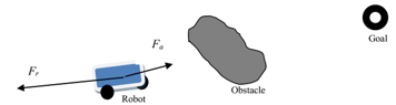
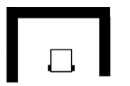
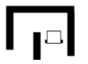
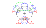
In this case, one can picture the robot as if it is subjected to two forces: an attractive force Fa due to the goal action and a repulsive force Fr due to the obstacle action as it is shown in Figure 1. The resultant force that acts on the robot may be determined by properly weighting the distance and direction. However, this would necessitate more tuning due to imperfect sensors and practical considerations. Therefore, to deal with obstacles, we choose the wall following approach while switching between the two cited behaviors with some added precautions to avoid the swinging effect. This method, which finds its application mainly to execute the corridor and wall following activity, is used in this work to avoid unforeseen obstacles. It could also help the robot reaching its goal in a blind fashion when the mobile robot makes the wall its main guidance. Tracking the wall would be an interesting application when dead-reckoning methods suffer from cumulative errors [15]. Wall following approach is as well very helpful in situations like being trapped in a cul-de-sac (Figure. 2-a) or when the mobile robot finds itself in a labyrinth-like situation (Figure. 2-b).
3. Obstacle avoidance using wall following approach
3.1 Problem formulation
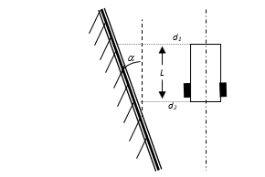
Many papers have dealt with wall following based on sensorial information such as IR sensors [16], US sensors [17], or visual navigation [18]. Ultrasonic and Infrared sensors are used for their relatively low cost, reliability and widespread availability. If the mobile robot evolves along a corridor, it will face two choices. Depending on its current situation with respect to the walls, the autonomous mobile robot should make a decision. Obviously, the robot follows the wall on its left side if the wall following task is chosen given only left sensor inputs, and likewise for the wall following on the right side. This decision may, for instance, be taken depending on the side that is closer to the wall. Hence, in case of the left wall following behavior, we use the two sensors on the left side of the mobile robot that give us the distances d1 and d2 as it is shown in Figure 3. But, if the mobile robot chooses to follow the wall being in its right side, the right wall following behavior is activated instead.
These two behaviors are mutually exclusive, which means that the activation of the first prevents the second to happen. This activation occurs when there are not obstacles on the front of the robot or there is only a detection of the wall that is to be followed. The implementation of the fuzzy logic controller is based on the sensorial information obtained from the two lateral US sensors, which give us the distance to the wall. In fact, this information is essential in determining the error angle between the actual current heading and the wall orientation. Our aim is to make this error equal to zero, such that the robot will always be in parallel to the wall.
3.2 The adopted strategy
Our idea lies on the following strategy. Consider the configuration of the mobile robot with respect to the wall and consider the distances d1 and d2 measured by the two lateral US sensors as it is shown in Figure 3. It is clear that the error angle a between the actual current robot heading and the wall orientation is given by equation (1)![]()
Where L is the length of the mobile robot. In this scheme, the desired position of the mobile robot is defined relative to the wall emplacement such that the robot maintains a desired distance. The distance that should be maintained between the mobile robot and the wall is chosen to satisfy an arbitrary security distance range D + 2e, such that e is a chosen tolerable offset error to avoid swinging or chattering behavior. In this case, the robot may be found in three possible regions, as it is clear from Figure 4.
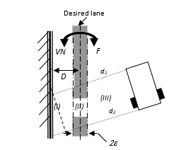
From Figure 4, one can see the inner region (I), the desired region (II) and the outer region (III). If the robot lies in the inner or outer regions, an action should be provided to drive it toward the desired region II. Considering the above stated requirement, our goal is to propose a robust fuzzy controller that maintains the mobile robot within region II.
4. Mobile robot Type-2 fuzzy motion control
The motion of the mobile robot may be controlled and adequately adjusted by many types of controllers. In this work, we choose the fuzzy logic control because we believe in its robustness for controlling nonlinear systems and its immunity in face to parameter variations and uncertainties. Introduced in 1965 by L. A. Zadeh from the University of California at Berkley [19], Fuzzy logic proved to be a strong tool for controlling complex systems. Using knowledge and experience, one can easily derive the rule base on which the fuzzy controller strongly depends. However, the presence of uncertainties in any system control requires thinking on extending type-1 fuzzy sets to type-2. In fact, the basic blocks used for designing the type-2 fuzzy controller are the same as those used with type-1; these include fuzzification, inference engine and defuzzification. The only difference lies on output processing block, where the defuzzifier is not considered as the solely block but contains a type reducer and defuzzifier blocks. The type reducer is added because of its association with the nature of the membership grades of the elements that are no more a number within the interval [0 1], but a fuzzy set of type-1.
4.1 Interval Type-2 fuzzy logic system (IT2FLS)
The interval type-2 fuzzy set is completely described by the footprint of uncertainty (FOU). The FOU is a bounded region that uses an upper and lower type-1 membership function. By definition [14], an interval type-2 fuzzy set denoted by is expressed as![]()
The upper bound and the lower bound of the FOU( ) are expressed respectively as and . Hence, is just the interval [ ]. A type-2 Fuzzy Logic System FLS (T2FLS) is characterized by IF-THEN rules, where the premises and the consequences sets of the rules are of type-2.
More details regarding the fundamentals of fuzzy control and design can be found in many textbooks such as Mendel [20], Wang [21], Passino and Yurkovich [22].
4.2 Design of a type-2 fuzzy obstacle avoidance behavior
In this subsection, we give the appropriate design of a Type-2 fuzzy controller based obstacle avoidance behavior. This fuzzy controller is composed of primary and secondary Interval Type-2 fuzzy controllers.
4.2.1. Primary Interval Type-2 fuzzy controller
Type-2 fuzzy logic controller is similar to Type-1. The structure of the rules is the same as for that of type-1, but uncertainties are added in both the antecedent and consequent parts of each rule to account for uncertainties that come especially from sensors and/or when the circumstances are so fuzzy.
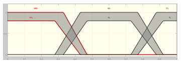
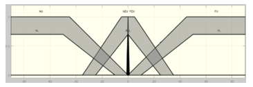
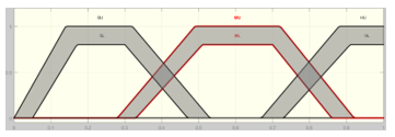
a) Fuzzifier: This input block maps a real-valued variable x to an interval Type-2 fuzzy set . All the values of all variables representing the input and the output of the system are fuzzified. We consider three fuzzy membership functions for the distance d with labels standing for Very Near, for Near and for Far, as it could be seen from Figure 5. In the same manner, we consider four membership functions for the mobile robot orientation with labels for Negative, for Negative Zero, for Positive Zero and for Positive as it is depicted in Figure 6. The geometries of the membership functions are chosen arbitrary. The outputs of the fuzzy controller are the left and right velocities of the driving wheels, implemented with three linguistic variables defined as: Velocity: vl, vr= { – Slow, – Medium, – High} on a normalized universe of discourse (Figure 7). Note that the symbol tilda above each label indicates that the fuzzy membership functions are of type-2. The two lateral US-sensors provide the sampled distance data d1 and d2, which are used to determine the two crisp input variables: d, such that d=min(d1,d2), and the error angle a given by equation 1. These crisp inputs are converted into a fuzzy singleton and are mapped to the fuzzy sets with an interval degree [ ].
b) Fuzzy inference engine: Once the input and output variables are defined, fuzzy inference engine is used to design the rule-base composed of IF-THEN rules to convert the inputs into output membership functions. It accomplishes the intersection and union of type-2 sets and performs compositions of type-2 relations.
The set of linguistic rules describe the desired behavior. Since the robot has the possibility to follow the wall on its right or the wall in its left side, we carefully have to set the rules adequately. The knowledge bases related to the wall on the left and the right sides of the robot are reported in Tables 1 and 2 respectively. For instance, we can have rules of the form: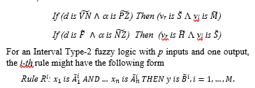
Under this bloc, the fuzzy min t-norm operation is implemented. For a crisp input vector, i.e., x=x’, the rule firing strength is given by type-1 fuzzy set [23].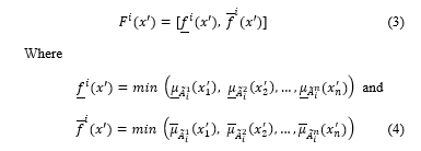
However, one can notice that no decision is taken when the robot enters the desired region II. We have marked this situation by a cross in the second row of Tables 1 and 2 to show that no decision is taken for these cases. In fact, whenever this situation is met, a secondary Interval Type-2 fuzzy controller is called to maintain the mobile robot in the desired region while keeping its orientation parallel to the wall. The details of this controller will be discussed latter.
c) Type reducer: This block found in the output processing is present in order to map the Interval T2FLS into a T1FLS. May be the most widely used type reducer among the many existing ones is the center of sets type reducer proposed by Karnik and Mendel [24]. It is characterized by the interval set determined by its left and right end points yl and yr and described by the following expression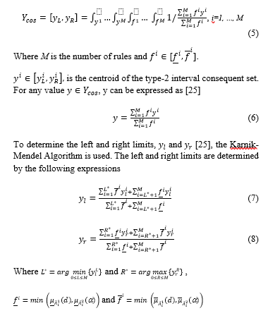
d) Defuzzifier: This second block constituting the output processing converts the T1FLS into a crisp number; i.e., the fuzzy variables from the type reducer are converted into a real valued variable. Hence the centroid of the type-1 fuzzy set contain two fuzzy singletons, and the final output is their average written as![]()
Table. 1. Rule base for left wall following fuzzy controller
| a
d |
||||
| vr= | vr= | vr= | vr= | |
| vl= | vl= | vl= | vl= | |
| X | X | X | X | |
| vr= | vr= | vr= | vr= | |
| vl= | vl= | vl= | vl= |
Table. 2. Rule base for right wall following fuzzy controller
| a
d |
||||
| vr= | vr= | vr= | vr= | |
| vl= | vl= | vl= | vl= | |
| X | X | X | X | |
| vr= | vr= | vr= | vr= | |
| vl= | vl= | vl= | vl= |
In our case the i-th rule is written as
Rule Ri: ,
i=1, …, 12
The speed of the right and left wheels are computed using the centroids for each aggregated Lower Membership Function (LMF) and Upper Membership Function (UMF). The speed for the left wheel is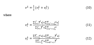
The speed for the right wheel, , is determined analogously.
4.2.2 Secondary Interval Type-2 fuzzy controller
The goal of the secondary Interval Type-2 fuzzy controller is to maintain the mobile robot within region II. For better compromise between good performances and reduced rules, the knowledge base is constructed using 25 rules as they are formulated in Table 3, which represent instructions to the robot to maintain its error angle to zero value. Input variables for this fuzzy logic controller are the error angle a and its time derivative da. The outputs are again the right and left velocities of the driving wheels. For the design of the fuzzy logic controller, we assume that the cardinality of the input and output sets are the same and equal to 5. We propose to use the following labels for the three sets: { – Negative Large, – Negative, – Zero, – Positive, – Positive Large}. The membership functions corresponding to the inputs a and da, are shown in Figure 8 and those corresponding to the outputs are shown in Figure 9. The symbol tilda above each label indicates again that the fuzzy membership functions are of type-2. For the right wall following, we either construct a new rule base or keep the previous one by making a small change in equation (1) while permuting the distances d1 and d2 as in equation (13).![]()
The design of the secondary Interval Type-2 fuzzy controller follows exactly the same steps as those presented in sub-section 4.2.1, for the two fuzzy inputs: the angle error a and its variation da.
The velocities responsible for maintaining the mobile robot within region II are equally given by equations (8) and (9), such that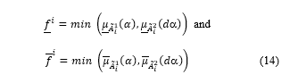
On the other hand, the mobile robot should know the orientation it should take in case it is trapped in a local minimum as it is shown in Figure 2.
The obstacle avoidance algorithm must determine the sign of the orientation angle given by equation (15).![]()
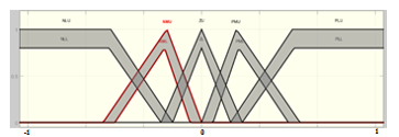
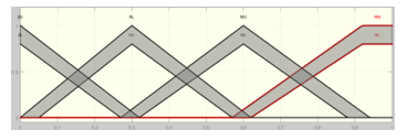
Table. 3. Rule base for the lane following fuzzy controller
| a
da |
|||||
| vr= | vr= | vr= | vr= | vr= | |
| vl = | vl= | vl= | vl= | vl = | |
| vr= | vr= | vr= | vr= | vr= | |
| vl= | vl= | vl= | vl= | vl= | |
| vr= | vr= | vr= | vr= | vr= | |
| vl= | vl= | vl= | vl= | vl= | |
| vr= | vr= | vr= | vr= | vr= | |
| vl= | vl= | vl= | vl= | vl= | |
| vr= | vr= | vr= | vr= | vr= | |
| vl= | vl= | vl= | vl= | vl = |
4.3. Reaching the Goal
Reaching the goal behavior, allows the mobile robot to navigate toward the target. Meanwhile, if the robot encounters an obstacle, the control switches immediately to wall-following behavior. “Reaching the Goal” and “Wall-Following” are two mutually exclusive behaviors. The activation of the first behavior prevents the second to happen. Figure 10, illustrates this operation using a flow chart. In contrast to the obstacle avoidance type-2 fuzzy controller, reaching the goal behavior is designed using a Type-1 fuzzy controller. The input variables are the distance, from the current mobile robot location to the target, and orientation angle, which measures the heading of the mobile robot with respect to the target point. For our convenience, we define seven fuzzy membership functions for the input distance with labels Z for Zero, NS for Near Small, S for Small, M for Medium, F for Far, VF for Very Far, and VVF for Very Very Far. Figure 11 illustrates the corresponding membership functions. In the same manner, we define seven membership functions for the orientation angle error with labels LN for Large Negative, SN for Small Negative, N for Negative, Z for Zero, P for Positive, SP for Small Positive and LP for Large Positive as it is depicted in Figure 12. The shape of the membership functions are chosen arbitrary and their emplacement along the universe of discourse has been carefully and adequately fixed after some experimental trials leading to a smooth navigation. The fuzzy outputs are again the right and left velocities of the driving wheels, whose shapes are trapezoidal on a normalized universe of discourse, as shown in Figure 13. We define for this application the following labels: Z for Zero, NZ for Near-Zero, S for Small, M for Medium, H for High, VH for Very-High and VVH for Very-Very-High.
Table 4 illustrates the fuzzy rules responsible of guiding the mobile robot to its final destination. The implementation of the fuzzy controller follows the steps of a conventional fuzzy controller, where one can find the main three blocks: the fuzzifier, the inference engine and the defuzzifier.
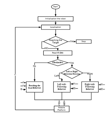
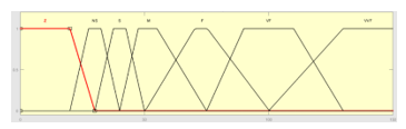
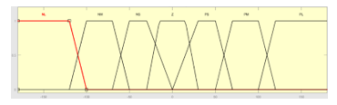
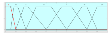
Table. 4. Rule base for the “ Reaching the Goal” behavior
| j
d |
NL | NM | NS | Z | PS | PM | PL |
| Z | LZ | LZ | LZ | LZ | LS | LS | LM |
| RM | RS | RS | RZ | RZ | RZ | RZ | |
| NS | LNZ | LNZ | LZ | LNZ | LM | LVH | LVH |
| RVH | RVH | RM | RNZ | RZ | RNZ | RNZ | |
| S | LNZ | LNZ | LNZ | LS | LVH | LVH | LVVH |
| RVVH | RVH | RVH | RS | RNZ | RNZ | RNZ | |
| M | LNZ | LNZ | LNZ | LM | LVH | LVH | LVVH |
| RVVH | RVH | RVH | RM | RNZ | RNZ | RNZ | |
| F | LNZ | LNZ | LS | LVH | LVH | LVH | LVVH |
| RVVH | RVH | RVH | RVH | RS | RNZ | RNZ | |
| VF | LNZ | LNZ | LM | LVH | LVH | LVH | LVVH |
| RVVH | RVH | RVH | RVH | RM | RNZ | RNZ | |
| VVF | LNZ | LNZ | LS | LVVH | LVH | LVH | LVVH |
| RVVH | RVH | RVH | RVVH | RS | RNZ | RNZ |
5. Experimental results
5.1 The mobile robot description
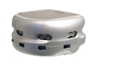
The mobile robot used in this work is Khepera III, a wheeled mobile robot from K TEAM Corporation. It is a mini mobile robot with functionality similar to larger robots used in research and education. It is an automated differential drive guided vehicle designed and equipped for autonomous and intelligent tasks as shown in Figure 14. The platform operates as a client in a client-server environment. Khepera is provided with Infrared and US-range-finder. It comes standard with five US transmitter/receiver pairs covering the front and the sides of the robot. We depict in Figure 15 the Khepera US sensors. To calculate the pose information of the robot we used the dead-reckoning equations.
5.2 The real experimentation Scenarios and Results
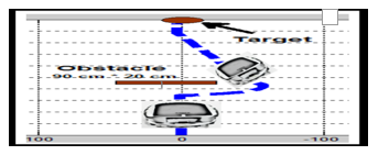
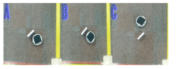
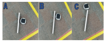
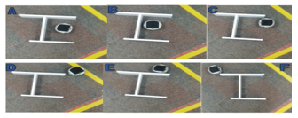
Various scenarios were set-up to test our proposed method in a real environment with different scenarios. These experimental results will determine the robustness, accuracy, adaptability and efficiency of the proposed method. For each scenario, we use the Khepera mobile robot platform, and matlab as a programming platform language. We tested the proposed system by using tens of scenarios; in this section, we are going to illustrate six of them. We selected six scenarios with various configuration, different shapes, and unknown environment. For all scenarios, the Khepera moves from the initial O(0mm, 0mm) point to the target point T(0mm, 1000 mm). Note that, the x-y data measurements are stored during the movement of the robot and plot by Matlab to get the graphs. In the first scenario, the Khepera robot navigates in a simple environment with one obstacle, as illustrated in Figure 16. During its motion to the target, the mobile robot encounters an obstacle. In this situation, the robot stops moving, determines the angle q from equation 15 and turns 90° clockwise due to the negative sign of the angle. The robot activates the obstacle avoidance behavior using the wall following approach. When the path is clear, the obstacle avoidance is inhibited and the Go-to-target behavior is re-activated. Figure 17 illustrates the real experimentation of this scenario.
In a second analog scenario, we simply change the length of the obstacle by considering a taller one. We remark that the mobile robot exhibits the same behavior as it did previously. We show in Figure 18 the plot of the experimental results, while Figure 19 illustrates the real experimentation.
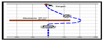
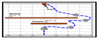
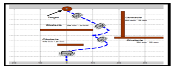
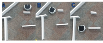
In the third scenario, the Khepera robot navigates in a somewhat difficult environment with two long obstacles, as illustrated in Figure 20. In this scenario, during the movement of the robot toward its target, it faces the first obstacle of size (300 mm x 20 mm) and a second one of size (700 mm x20 mm). The robot determines the angle q and turns 90° clockwise. The robot makes a first call to the wall-following algorithm to avoid the first obstacle. After passing the obstacle, the Go-to-Target algorithm is called in order for the robot to navigate toward its final configuration. However, in its path to the target a second obstacle is encountered. Again, the go-to-target is inhibited and the wall following behavior is activated. Immediately after passing the obstacle, the mobile robot regains control on the go-to-target behavior. The plot of this scenario is shown in Figure 20 and Figure 21 illustrates the real experimentation.
In the fourth scenario, the mobile robot navigates until a cul-de-sac situation is met, as it is can be seen from Figure 22. In this scenario, the mobile robot succeeds in escaping from this situation to join its final configuration using the same procedures. Figure 23 illustrates the real experimentation of this scenario.
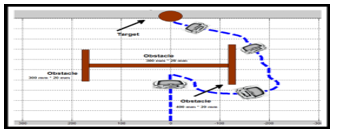
In the fifth scenario, the robot is used to navigate in an environment embedded with many obstacles. The purpose of this manipulation is to show the validity of the approach in case of difficult situations. As we can notice from Figure 24, the mobile robot navigates successfully around the obstacles until the target is reached. Figure 25 illustrates the real experimentation of this scenario.
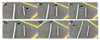
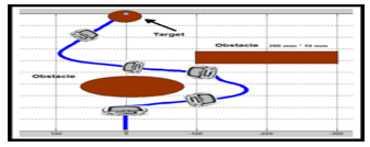
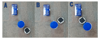
Figure 26 depicts the sixth scenario, where we repeated the fifth scenario using different obstacles shapes. During its motion, the robot faces the first circle shaped obstacle. In this case, the avoid obstacle behavior is executed using the wall-following approach, immediately followed by the Go-to-Target when the path is clear. Figure 27 illustrates the real experimentation of this scenario.
6. A Comparison study with PSO-Fuzzy methodology
In this section, we aim to compare the proposed method (Obstacle Avoidance Using Wall-Following Strategy) with another work, which uses a Partial Swarm Optimization-Fuzzy (PSO-Fuzzy) for navigation and obstacles avoiding [26].
From an experimental point of view, and to compare the performance of the proposed method with PSO-Fuzzy, each method was executed in two scenarios. The first scenario is simple and the second is somehow complicated. Each method was executed from the same startup point O(0 cm, 0 cm) to the target point T(0 cm, 100 cm). The comparison will include the traveled distance and the execution time. Plots of the results of the first and second scenarios of the experiments are shown in Figures 28 and 29 successively. The performance indexes are listed in Table 5. In fact, we have used the distance travelled by the mobile robot to go from the starting point to the destination point, whereas the second metric used is the time spent by the mobile robot to finish its travelling distance.
In these scenarios, we applied the two methods to moving the robot from the initial point to the target with the obstacle avoidance strategy. When comparing the two methods, it is obvious from the results reported in Table 5 that the proposed method performed better than the PSO-fuzzy one.
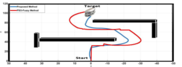
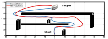
Table 5: Performance indexes
|
Parameters |
Proposed Method | PSO-Fuzzy Method | |
| First scenario | Execution time | 33.83 sec | 46.46 sec |
| Traveled distance | 124 cm | 163 cm | |
| Second scenario | Execution time | 48.12 sec | 69.35 sec |
| Traveled distance | 184 cm | 219 cm | |
7. Conclusion
In this paper, a complete navigation mobile robot control is used to reach a given target while avoiding unforeseen obstacles. To satisfy these two requirements, a fuzzy logic design has been implemented for the two behaviors. The first behavior is achieved by designing a fuzzy controller that uses the distance and the orientation as inputs. The controller generates the required wheels velocities to drive the mobile robot to its destination along a smooth path. In case the mobile robot encounters an obstacle, it switches to the obstacle avoidance behavior designed using a wall following approach. A new fuzzy controller approach based on Type-2 fuzzy sets has been presented for obstacle avoidance using wall following methodology. To achieve this requirement, we divided the robot environment into three regions, two transient regions and one stable region. Whenever the mobile robot finds itself in the transient regions, the first fuzzy controller is activated to pull the mobile robot to the lane that is parallel to the wall. Once trapped in this region, the first fuzzy controller is inhibited and the second is activated such that the mobile robot remains within the limits of the lane. The mobile robot keeps moving within the stable region of displacement until a new situation appears, otherwise the go-to-target behavior is activated with Type-1 fuzzy controller and the mobile robot heads for the target point. Experimental works are carried out on the mobile robot Khepera III. The experimental results obtained are very satisfactory and prove the validity of the proposed approach, which is simple, and does not require complicated and burden computations compared to other methods. As an extension to this work, we plan to adapt this methodology to the mobile robot PowerBot from Adept Corporation.
- Crawford, Ian A., and Katherine H. Joy. ”Lunar exploration: opening a window into the history and evolution of the inner Solar System.” Philosophical Transactions of the Royal Society of London A: Mathematical, Physical and Engineering Sciences 372.2024: 20130315, 2015.
- G. Pessin, D. O. Sales, M. A. Dias, R. L. Klaser, D. F. Wolf, J. Ueyama, FS Osorio & Vargas, P. A., “Swarm intelligence and the quest to solve a garbage and recycling collection problem”. Soft Computing, 17(12), 2311-2325, 2013.
- L. Danielli and G. MB de Oliveira. ”A cellular automata ant memory model of foraging in a swarm of robots.” Applied Mathematical Modelling, Vol. 47, pp.551-572, 2017.
- C. Rodrigo, M. Figueiredo, and E. A. Antonelo. ”Evolutionary fuzzy system for architecture control in a constructive neural network.” Computational Intelligence in Robotics and Automation, 2005. CIRA 2005. Proceedings 2005, IEEE International Symposium on. 2005.
- F. M. Marchese, ”A directional diffusion algorithm on cellular automata for robot path-planning.” Future Generation Computer Systems Vol. 18, issue7 pp. 983-994, 2002.
- Y. Liu, R. Fu, J. Wang, Y. Ou, X: Wu, A: Peng, “A Wall-Following Strategy for Mobile Robots Based on Self-Convergence”; Proceedings of the 2011 IEEE, International Conference on Robotics and Biomimetics, December 7-11, Phuket, Thailand, 2011.
- X. Wang, Z. G. Ho, M. Tan, Y. W., L. Hu, “The wall-following controller for the mobile robot using spiking neurons”, Int. Conf. on Artificial Intelligence and Computational Intelligence, 2009.
- R. Braunstingl, P. S.anz – J. M. Ezkerra, “Fuzzy Logic Wall Following of a Mobile Robot Based on the Concept of General Perception”, ICAR ‘95, 7th Int. Conf. on Advanced Robotics, Sant Feliu De Guixols, Spain, pp .367-376, Sept., 1995.
- I. Gavrilut, V. Tiponut, A. Gacsadi, L. Tepelea, “Wall-following Method for an Autonomous Mobile Robot using Two IR Sensors”, 12th WSEAS International Conference on Systems, Heraklion, Greece, July 22-24, 2008.
- C. H. Hsu and C. F. Juang, Evolutionary Robot “Wall-Following Control Using Type-2 Fuzzy Controller with Species-DE Activated Continuous ACO”, Fuzzy Systems, IEEE Transactions Vol. 21 Issue: 1, pp. 100-112, Feb. 2013.
- D. Lima, C. Tinoco, J. Viedman and G. Oliveira, “Coordination, Synchronization and Localization Investigations in a Parallel Intelligent Robot Cellular Automata Model that Performs Foraging Task” .In Proceedings of the 9th Int. Conf. on Agents and Artificial Intelligence ISBN 978-989-758-220-2, pp. 355-363, 2017.
- N. Baklouti1, R. John2, A. M. Alimi, Interval Type-2 Fuzzy Logic Control of Mobile Robots, Journal of Intelligent Learning Systems and Applications, vol.4, pp. 291-302, 2012.
- H. Hagras, “A Hierarchical Type-2 Fuzzy Logic Control Architecture for Autonomous Mobile Robots,” IEEE Transactions on Fuzzy Systems, Vol. 12, No. 4, pp. 524-539, 2004.
- C-F Juang, and C-H Hsu, “Reinforcement Ant Optimized Fuzzy Controller for Mobile-Robot Wall-Following Control”, IEEE Transaction on Industrial Electronics, Vol. 56, no. 10, October 2009.
- I. Dumitrache, M. Dragoicea, “Some Problems of advanced mobile robot control”, J. of Control. Engineering and Applied Informatics, Vol. 7, No. 4, pp. 11-30, 2006.
- H. Park, S. Baek and S. Lee, “IR Sensor Array for a Mobile Robot”, Proceedings of the 2005 IEEE/ASME Int. Conf. on Adv. Intell. Mecha., Monterey, California, USA, 24-28 July, 2005.
- D. P. Stormont, C. T. Abdallah, R. H. Byrne and G. L. Heileman, “ A Survey of Mobile Robot Navigation Methods Using Ultrasonic sensors”, Space and Robotics, ISBN (print): 978-0-7844-0337-2, 1998.
- F. Bonin-Font, A. Ortiz and G. Oliver, ” Visual Navigation for Mobile Robots: a Survey, “Journal of Intelligent and Robotic System”, Vol. 53, issue 3, pp. 263-296, Nov. 2008.
- L.A. Zadeh,”Fuzzy Sets,” Information Control, vol. 8, pp. 338-353, 1965.
- J. M. Mendel, Uncertain Rule-Bused Fuzzy Logic Systems: Introduction and new directions. Prentice Hall. NJ_ 2001.
- L. X. Wang, A course in Fuzzy systems and Control, Prentice-Hall, Englewood Cliffs, NJ, 1997.
- K. M., Passino and S. Yurkovich, Fuzzy Control, Addison Wesley Longman, Menlo Park, CA, 1998.
- Q. Liang and J. Mendel, “Interval type-2 fuzzy logic systems: Theory and design,” IEEE, Trans. Fuzzy syst., vol. 8, no. 5, pp. 535-550, Oct. 2000.
- N. N. Karnik and J. M. Mendel,, “Type-2 fuzzy logic systems: Type-reduction,” in IEEE Syst., Man, Cybern. Conf., San Diego, CA, Oct. 1998.
- Dongrui Wu, Jerry M. Mendel, “Enhanced Karnik-Mendel Algorithms,” IEEE Transactions on Fuzzy Systems, 17(4), 923-934, 2009.
- Algabri Mohammed, Hedjar Ramdane, Hassan Mathkour, Khalid Al-Mutib, and Mansour Alsulaiman. “Optimization of Fuzzy Logic Controller Using PSO for Mobile Robot Navigation in an Unknown Environment.” Applied Mechanics and Materials 541: 1053-1061, 2014.