Coal Seam Methane Abatement and Utilization Techniques with Availability and Feasibility Criteria

Adv. Sci. Technol. Eng. Syst. J. 1(1), 1–10 (2016);
 DOI: 10.25046/aj010101
Methane found in coal seams is about 17% of total methane emissions by human activities and 8% of world’s greenhouse gases emissions. Mine methane can be generated through different streams of coal mines like degasification of underground coal mines, ventilation of air in coal seams, post mining processes and surface mining. Methane from ventilation air is the most abandoned form obtained from coal seams but its utilization as an energy source is very difficult due to high flow rate and low concentration of methane in vented air. This discussion not only includes VAM’s mitigation but also its utilization techniques which have been developed mostly based on oxidation and underdeveloped with their technical feasibilities and operational parameters.
1. Introduction
Methane released from coal seems is about 17% of the emission from human activity resource and 8% of total emissions of greenhouse gases [1]. Coal mine methane is actually refers the methane release before, during and after operational mining. There are three streams of methane emitting from gassy mines: (1) ventilation air methane (2) coal bed methane and (3) abandoned mine methane. Table 1 shows the percentage of emissions of gassy mine methane. Methane released during coal mining could be diluted through ventilation fans. Methane exhausted after dilution into atmosphere called ventilation air methane is about 64% of the total release from coal seams [2].
Ventilation air methane mitigation and utilization as an energy source are not an easy task because of its dilution and variation in concentration and flow rate. Low concentration of methane in VAM is a major problem and it can only be resolved by enriching the methane’s concentration through some techniques but still there is no effective technology available to increase methane concentration so all the work is being done on focusing on low content ventilation air methane oxidation. According to combustion kinetic mechanism there are two types of oxidation, thermal and catalytic. There are two basic classifications of utilization technologies of ventilation air methane one for the supplementary uses and the other for the principle uses. Supplementary usage technologies are gas turbines, coal-fired power stations and internal combustion engines where combustion processes used ventilation air as a substituent for ambient air. While in the principle usage technologies VAM is used as a primary fuel. This technology includes CANMET catalytic flow reversal reactors (CFRR), MEGTEC thermal flow reversal reactors (TFRR), CSIRO lean burn catalytic turbine, EDL recuperative gas turbine and CSIRO catalytic combustor (CMR) that could be in combination with adsorption chiller and coal drying or heating or cooling. CFRR and TFRR can mostly provide only mitigation of methane by combustion to minimize greenhouse impact without extracting energy for power generation while turbine technologies are effective for both mitigation and extraction of methane. 1% and 1.6% methane concentration is required respectively which could be obtained by the combination of VAM and gassy mine drainage gas. Through successful installation of a concentrator, the concentration of methane could be increased up to 30% and it would make a breakthrough for the utilization techniques development [3].
Table 1: Gassy mine methane emission
| Gassy mine streams | Percentage of Methane |
| Ventilation Air | 0.1-1% |
| Pre Mining drainage gas | 60-95% |
| Post Mining drainage gas | 30-95% |
This review categorized not only the currently developed coal mine mitigation and utilization techniques but also discusses the underdeveloped techniques with their feasibility for implementation. In Figure 1 there is a detailed classification of methane mitigation and utilization techniques according to their principles, mechanism and application.
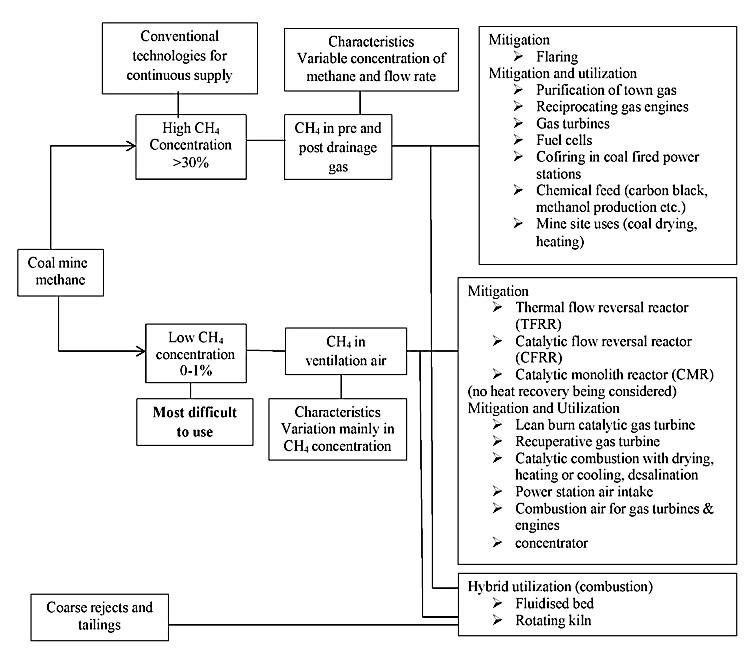
Table 2: Technology classification of drainage gas
| Technology | Mechanism | Principle | Application Status |
| Purification
· Purification for towm gas |
Separation | Gas purification process | Demonstrated in full scale units providing pipeline gas |
| Power generation/cogeneration
· Reciprocating gas engine · Conventional gas turbine · Co-firing in power stations · Fuel cell power generation |
Combustion
Combustion Combustion Electrochemical reaction |
Combustion in engine combustion
Combustion in conventional gas turbine/engine Combustion inside boilers Electrochemical process |
Utilization-demonstrated
Utilization-demonstrated Utilization-demonstrated Utilization-being proposed as a concept |
| Chemical feedstocks
· Chemical feedstocks: methanol and carbon black |
synthetic | synthetic processes | Utilization-being tested in a pilot scale unit |
Table 3: Main and distinguishing features of purification technologies
| Technology | Solvent adsorption | Pressure swing
adsorption |
Cryogenic separation | Membrane separation |
| Sorbent | Liquid | Solid | n/a | n/a |
| Phase change | No | No | Yes | No |
| First stage
Deoxygenation |
Yes | No | Yes | |
| Methane recovery | 96-98% | Up to 95% | 98% | |
| Technical issues
for application |
Unsuitable for
nitrogen removal |
Small to medium size | Scaling up problem |
2. Mitigation of Drainage Gas
It is possible to mitigate methane from coal mining. We can capture methane from coal mines for different applications and during these applications CH4 is converted into carbon dioxide and due to this the impact of greenhouse reduces to 20 times [4].The following are some of the abatement options of drainage methane [5-9]:
- Installation of vapour recovery units and flare systems.
- In production install flash tank separators.
- Replace high bleed with low bleed pneumatic devices.
- Installation of plunger lifts system.
- For pipeline venting use portable compression evacuation
- Green completions.
- Fuel gas retrofit for blow down valve.
- Direct inspection and maintenance at compressor stations.
3. Utilization Options for Drainage Gas
Concentration of drained gas is more than 30% could be used in different areas of industries. Table 2 shows a technology classification for drainage gas. US EPA has been summarized some of the option for the utilization of coal mine methane for drainage during and after mining operations [10]. These include:
- Coal mine methane can be used in blast furnaces, brine water treatment, cogeneration power systems, fuel cells, greenhouses, methanol production and coal dryers.
- Usage for heating mine ventilation air.
- Usage of coal-firing coal mine methane in industrial boilers.
- Formation of synthetic fuels.
- Increasing concentration of medium quality coal mine gas.
- Usage in internal combustion engines placed at coal mines.
All these technical options can be classified in three categories according to their applications: purification for gas pipelines, power generation and chemical feed stocks.
3.1. Town gas pipeline purification
Coal mine composed of 30-90% methane which could be the most effective source of fuel but it is generally vented to the atmosphere after its drainage. In fact sometimes it has been flared in mine which results a valuable loss of energy [10, 11]. Solvent adsorption, membrane separation, cryogenic separation and pressure swing adsorption are the main processes used for gas pipelines purification [12, 13]. Table 3 illustrates main features and differences of this technique.
3.2. Electricity generation
Generating power from drainage gas is an important option because of its significant electricity load. Every equipment needs electricity to run for instance mining machines, coal production plants, ventilation fans, conveyor belts and desalination plants. In fact ventilation system is running 24 hours a day and it utilizes large amount of electricity [11]. Table 4 shows power generation technologies with their feasibilities.
3.3. Chemical feed stocks
Coal seam methane can be used alternatively in chemical processes for the preparation of chemicals and synthetic fuels. Carbon black and methanol production are the two basic applications in this field [14, 15]. Table 5 shows distinguishing factors of these two technologies.
4. Ventilation Air Methane Mitigation
Coal mine methane has to be recovered for the safety of working environment and its utilization in various applications. Methane from coal seams is mostly emitted as ventilation air methane which has a very low concentration of CH4 due to large volume of air so its utilization became more difficult. To reduce the overall impact of methane gas towards greenhouse effect it is very important to increase its concentration before utilization. Still there is no effective technique to maximize the methane percentage in ventilation air but working on its development is under progress until then majority of work has been focused on the VAM’s oxidation. Oxidation reduces greenhouse gases impact 20 times [16-18].
4.1. Oxidation of methane
In this process methane is converted into carbon dioxide through its combination with oxygen as well heat is released which in turn used as energy source. Oxidation of VAM could be thermal or catalytic. The overall combustion reaction is represented by the following equation however many free radical chain reactions are involved in its actual reaction mechanism [19]:
![]() Carbon monoxide (CO) and carbon dioxide (CO2) are produced by the increasing or decreasing air to methane ratio which are given as:
Carbon monoxide (CO) and carbon dioxide (CO2) are produced by the increasing or decreasing air to methane ratio which are given as:
![]()
![]()
Other parallel reactions are given as:
![]()
![]()
![]()
Catalytic oxidation is a multi-step process which involves:
- Diffusion to the catalyst surface.
- Adsorption on to the catalyst.
- Desorption of the product species from the catalyst surface.
- Diffusion back into the bulk.
Figure 2 shows a catalytic oxidation mechanism proposed by Oh et al. [20]. For complete oxidation at low temperature it is observed that Palladium and Platinum are the most active catalyst. Lee et al. [19] experimentally proved that Pd/Al2O3 by far the best catalyst followed by Pt/Al2O3.
5. Utilization Techniques of Ventilation Air Methane
VAM is used as supplementary (ancillary) fuel and principle fuel in different technologies [21, 22]. Table 6 shows mitigation and utilization techniques for principle and ancillary fuel usage.
Table 4: Distinguishing characteristics of mine methane fired power generation technologies
| Technology | Gas engines | Gas turbines | Fuel cells | Co-firing in power stations |
| Mechanism | Combustion | Combustion | Electrochemical reaction | Combustion/rebuming |
| Operating Temperature | 1800-2000ºC | 1400-1650ºC | 150-200ºC, 600-950ºC | 1400-165s0ºC |
| Maximum CH4 Requirement | 40% (spark ignition), 5% (homogenous compression ignition) | 30 % (conventional),
1% (catalytic turbine) |
Pre-drainage gas and medium quality post drainage gas (> 50%) | Not determined |
| Potential issues | Still underdevelopment,
high cost |
Limited sites |
Table 5: Comparison of production technologies of carbon black and methanol
| Technology | Methanol Production | Carbon black production |
| Mechanism | Synthesis reaction | Gas reduction reaction |
| Operating Temperature | 130-1000ºC | 150-1400ºC |
| Minimum CH4 requirement | 89% | Pre-drainage gas and medium quality post drainage gas (> 50%) |
| Potential Issues | Process water required | Process water required |
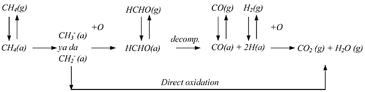
Table 6: Ventilation air methane technology classification as supplementary fuel
| Technology | Oxidation mechanism | Principle | Application status |
| Combustion air for conventional power station | Thermal | Combustion in of power station boiler furnace | Mitigation
Utilization–demonstrated in a pilot scale unit. and being considered for a full scale demonstration |
| Combustion air for gas turbines | Thermal | Combustion in conventional
gas turbine combustor |
Mitigation
Utilization–studied |
| Combustion air for gas
engine |
Thermal | Combustion in gas engine combustor | Mitigation
Utilization–demonstrated |
| Hybrid waste coal/ methane combustion in a kiln | Thermal | Combustion inside a rotating
combustion chamber |
Mitigation
Utilization–being preliminarily trailed in a pilot scale unit |
| Hybrid waste coal/ methane combustion in a fluidized bed | Thermal | Combustion inside a fluidized bed and freeboard | Mitigation
Utilization–being proposed as a concept |
| Thermal flow reverse reactor (TFRR) | Thermal | Flow reverse reactor with
regenerative bed |
Mitigation: demonstrated
Utilization–not demonstrated yet |
| Catalytic flow reverse reactor (CFRR) | Catalytic | Flow reverse reactor with
regenerative bed |
Mitigation: demonstrated
Utilization–not demonstrated yet |
| Catalytic monolith combustor | Catalytic | Monolith reactor with a
Recuperator |
Mitigation: demonstrated
Utilization–not demonstrated yet |
| Catalytic lean burn gas
turbine |
Catalytic | Gas turbine with a catalytic
combustor and Recuperator |
Mitigation: combustion demonstrated
Utilization–being developed in a lab scale unit |
| Recuperative gas turbine | Thermal | Gas turbine with a recuperative combustor and Recuperator | Mitigation: combustion demonstrated
Utilization–demonstrated in a pilot scale unit but needed further modification |
| Concentrator | N/A, adsorption | Multi stage fluidized/ moving bed using adsorbent, and a desorber | Mitigation and utilization: under development |
5.1. Principle fuel technologies
In combustion processes ventilation air methane can be utilized as a primary fuel [23, 24]. However, methane concentration in ventilation air sometimes does not meet with the operational requirement for a primary fuel applications, specially where a high quality supplementary fuel is required to recover energy for power generation [17, 25].The following are the some applications of VAM as principle fuel.
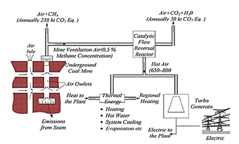
5.1.1. TFRR (thermal flow-reversal reactor), CFRR (catalytic flow reversal reactor) and CMR (catalytic monolith reactor) Technologies
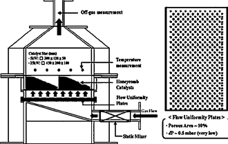
Principles of these three technologies are described in different places [23, 26, 27]. Both thermal and catalytic reactors work on flow reversal mechanism where Catalyst is the only difference between TFRR and CFRR [1]. TFRR oxidizes greater than 95% of CH4 while CFRR oxidizes 90% of CH4 in ventilation air methane in order to reduce greenhouse effect and valuable source of energy [28, 29]. Catalytic monolithic reactor implies a honeycomb type monolithic reactor. Because of its enormous benefits like high mass flows with very low pressure, high mechanical strength and high geometrical area, it is mostly used [30]. Some of the comparison features of these technologies are tabulated (Table 7). Figures 3, 4 and 5 are representing schematic diagram of TFRR, CFRR and CMR.
5.1.1.1. Concentration of methane
The low and variable concentration of methane in ventilation causes serious operational problems using TFFR and CFRR to generate power by recovering heat. A firm which manufactured TFRR, MEGTEC, has reported that thermal flow reversal reactors can show a sustain operation at 0.08% concentration of methane. However, another simulation results by S. Su., et al. indicated that if the concentration of methane is dropped down to 0.35% blow out would occur [31]. For a sustain operation of CFRR methane concentration should be above 0.1% [31]. Figure 6 shows the advantage of catalytic flow. An experimental result carried out by the work on catalytic combustion indicated that CMR will perform continuously if concentration of methane is not below 0.4% and a recuperate preheated the air up to 500oC by using flue gas from the catalytic monolith reactor [31, 32].
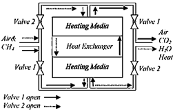
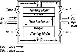
Table 7: Distinguishing features of reactor technologies using VAM as primary fuel
| Features | Thermal flow reversal reactor | Catalytic flow reversal reactor | Catalytic monolith reactor |
| Principle of operation | Flow reversal | Flow reversal | Monolith reactor |
| Catalyst | No | No | Yes |
| Auto ignition temperature | 1000ºC | 350-800ºC | 500ºC |
| Cycle Period Length | Shorter | Longer | Continuously |
| Minimum methane
Concentration |
0.2% | 0.08% | 0.4% |
| Applicability | Methane mitigation | Methane mitigation | Methane mitigation |
| Variability of methane
concentration |
Variable | Variable | Variable |
| Plant ize | Huge | Lager | Compact |
| Operation | More Complicated | More Complicated | Simple |
| Lifetime | N/A | N/A | >8000h for catalyst |
| NOx emission | N/A | Low | Low(< 1 ppm) |
| COx emission | Low | Low | Low( 0 ppm) |
| Possibility of recovering heat to generate power | May need additional fuel to increase methane concentration
and maintain it constant |
May need additional fuel to increase methane concentration
and maintain it constant |
May need additional fuel to increase methane concentration
and maintain it constant |
5.1.1.2. Recovery of heat
Heat extracted by combustion of methane for power generation highly depends on the constant methane concentration if it varies there is instability in the system and recovery of heat becomes difficult. It should only be possible if the concentration of methane above the minimum. This requires transference into the working fluid for example steam for a steam turbine and air for gas turbine. Some of the heat is needed to stabilize the temperature of the reactor and if the concentration of methane below its requirement most of the heat consumes in maintaining the temperature of the reactor. If the concentration of methane in ventilation air varies it is very difficult for normal heat exchangers to cope with the fluctuated temperature of the reactor. Experimental results carried out by Danell et al. [27] in the pilot thermal flow reactor unit have already been proven it. Therefore, an almost constant concentration of methane is required for recovery of heat for electricity generation which in turn requires addition of natural gas in feed air [33].
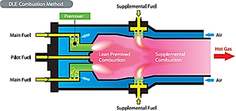
5.1.2. Lean burn gas turbines
In the modern world there are different lean burn gas turbines have been developed with a catalytic combustor which includes CSIRO lean burn catalytic gas turbine, Ingersoll Rand micro turbine and EDL’s recuperative gas turbine. Most of the heat from the combustion process to pre heat the VAM used by recuperative gas turbines. Table 8 represents some important difference among lean burn gas turbines. If the concentration of methane in vent air not above 2% there must be an addition of CH4 in the feed air so as to be used as a subsidiary fuel. Methane recovered from pre and post mining operations and low concentrated methane in ventilation air can also be used in these turbines [34]. An experimental result obtained from the recovered methane of two gassy coal mines of Australia which implemented 0.8% and 2% methane in gas turbines and found that 50% to 60% of the fuel for igniting 1% methane catalytic turbine while 30% to 60% of the fuel for igniting methane catalytic turbine is the ventilation air methane. It has also found that almost 100% ventilation air using 0.8% methane concentration for turbines and approximately 30% to 50% ventilation air used 2% methane concentration for turbines [35]. Figure 7 represents a schematic diagram of Lean burn gas turbines.
5.1.3. Concentrators
In several industries volatile organic compounds are recovered through concentrators. They enrich the concentration of methane in vent air and meet the requirement of concentrators. Concentrators increase the concentration of methane in ventilation air from 0.8% to above 20%. As a result of enrichment if methane’s concentration raised up to 30% then VAM could be used in conventional gas turbines for power generation [35].
5.2. Supplementary (ancillary) fuel technologies
The recovered VAM can be used as supplementary fuel to raise the combustion performance in the process of combustion. Basic utilization of VAM as ambient air are hybrid waste/coal methane combustion unit, gas turbines, pulverized coal-fired power stations and internal combustion engines. There is an uncertainty in the recovery of energy from these technologies because these units have safe connection to the mine shafts. But this mine site application and cannot be fully demonstrated and examined [3, 36, 37]. Table 9 illustrates comparison of supplementary usage of VAM technologies.
5.2.1. Hybrid waste/coal methane combustion units
Considering the mechanism of oxidation replacement of combustion air with ventilation air in hybrid waste/coal methane combustion in a fluidized bed and rotating kiln is same as the combustion of pulverized coal in boiler furnaces. However, the stabilization and organization principles of the combustion process are different [36].
Table 8: Distinguishing characteristics of Lean Burn Gas turbine techniques
| Feature | EDL recuperative turbine | CSIRO catalytic turbine | IR catalytic micro turbine |
| Principle of operation | Air heater inside combustion chamber | Monolith reactor | Monolith reactor |
| Catalyst | No | Yes | Yes |
| Auto ignition temperature | 700-1000ºC | 500ºC | N/A |
| Experience | Pilot Scale | Bench scale study on combustion | Conventional micro turbine development |
| Cycle Period Length | Continuously | Continuously | Continuously |
| Minimum methane
Concentration |
2.0% | 0.08% | 0.08% |
| Applicability | Methane mitigation and power generation and need additional fuel to increase methane concentration | Methane mitigation and power generation and need additional fuel to increase methane concentration | Methane mitigation and power generation and need additional fuel to increase methane concentration |
| Possibility of recovering heat to generate power | Feasible | Feasible | Feasible |
| Variability of methane
concentration |
Constant | Constant | Constant |
| Operation | Simple and stable | Simple and stable | Simple and stable |
| Lifetime | May be shorter due to high temperature combustion heat
exchanger |
>8000 h for catalyst, 20 years for turbine | N/A |
| NOx emission | Higher | Low (< 3 ppm) | Low |
| COx emission | Low | Low ( 0 ppm) | Low |
Table 9: Comparison of supplementary VAM usage technologies
| Technology | Feature | Combustion temperature | Technical feasibility and engineering applicability | Potential issues |
| Pulverized coal fired power station | Pulverized coal fired furnace | 1400-1650ºC | Tech: yes
Engg: not demonstrated at a mine site |
Limited sites
Potential operational problems to existing boilers |
| Hybrid waste coal methane in a rotating kiln | Rotating kiln | 1200-1550ºC | Tech: may be
Engg: not demonstrated at a mine site |
Self-sustaining combustion
Minimum requirement for waste coal quality |
| Hybrid waste coal/ methane in a fluidized bed | Fluidized bed | 890-950ºC | Tech: may be
Engg: not demonstrated at a mine site |
Minimum requirement for waste
coal quality Proving test needed for CH4 oxidation |
| Conventional gas turbines | Gas turbine | 1400-1650ºC | Tech: may be
Engg: not demonstrated at a mine site |
Small percentage of turbine fuel A lot of CH4 is emitted in by passing air for a single compressor machine. If two compressors are used there is increasing system complexity, and decreasing capacity of using ventilation air. |
| Internal combustion engines | Engine | 1800-2000ºC | Tech: yes
Engg: not demonstrated at a mine site |
Small percentage of engine fuel using a small percentage of ventilation air |
5.2.1.1. Fluidized bed
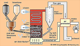
Numbers of pilot scale units utilizing ventilation air methane as a subsidiary fuel in units of fluidized bed combustionare preferred, even though there is no complete oxidation of methane occurs in these fluidized bed [38]. During the combustion process fluidized beds suspend solid fuels on upward blowing jets of air because of this there is a turbulent mixing of solids and gas. Bubbling of fluid gives more effective transference of heat and chemical reaction. All this process occur between the temperature of 800-950OC. The flue gases from the fluidized bed come in contact with sulphur absorbing chemicals like limestone. Adsorbent capture these more than 90% of these sulphur pollutants inside the boiler. Circulating fluidized bed is much more effective in operational point of view because it could deal with high flow rate of air, moving bed material, recirculation of high volume of bed material and hot cyclone separators. So this technique is potentially more significant in terms of simplified feed design and extension in the contact between flue gas and adsorbent, tube erosion and improves the efficiency of combustion and adsorption of sulphur dioxide [39]. Figure 8 represents a fluidized bed combustion reactor.
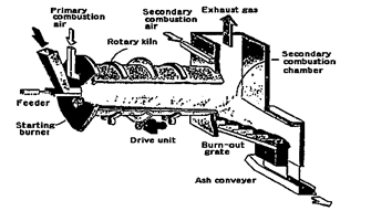
5.2.1.2. Rotating Kiln
In early 1990’s, the combustion performance of waste coal has been examined by Cobb [40]. The test results concluded that it was very difficult to carry out a sustain combustion process even a sufficient amount of supplementary fuel were used. Rotary kiln is not well suited for the combustion of low grade hard coal because of its open structure which can be applicable for burning of bulky fuels and wastes. Figure 9 illustrates the working of a rotary kiln. CSIRO Exploration and Mining not only wants to mitigate methane but also recover waste energy for generating electricity. They are quite promising about the efficient operational results from the combustion of waste coal in combination with drainage gas and vent air both inside the rotary kiln. But still there number of parameters is left for investigation to obtain feasible physical conditions in kiln for sustain combustion of waste coal and it seems to be difficult.
5.2.2. Conventional gas turbines
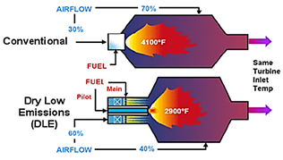
In this technique a small percentage of methane from ventilation air combines with the required fuel of turbine. This ventilation air not only diluted the combustion process but also cools down the turbine and because of it a sufficient fraction of methane will pass through the turbine without any combustion. To avoid this incomplete combustion a complex turbine system that not only require compressed from other source but also needed compressed ventilation air [34, 41]. If VAM is used with solar turbines then the concentration of methane should lower than 0.5% in order to maintain the unit system cool. If the concentration increases there will be more combustion and temperature of the inside of the rotor will raised up to a dangerous level [23]. Figure 10 shows a conventional gas turbine.
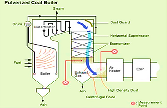
5.2.3. Pulverized coal fired power stations
Available combustions processes utilized the trapped ventilation air as an ambient air in large power stations. According to the results of a pilot scale study in Australia at a power station for this technique this method is applicable for the power plants that can be built near mine sites [42].
Power stations are not generally found near gassy mines because it is not a suitable technique. Figure 11 shows a pulverized coal firing. Variation in the concentration of methane and flow rate of air can cause a negative impact on the operational performances of the equipment. For instance if during combustion the concentration of ventilation air increased it can damage the equipment, residuals and slagging [34].
5.2.4. Internal combustion engine
Medium quality gas is used by internal combustion engines to generate electricity so it becomes more beneficial to use ventilation air as ambient in the combustion. This technology has a low capital cost with the usage of minimum percentage of VAM. During the combustion process more NOx is released because of high combustion temperature [42].
6. Conclusion
Anthropogenic emission of methane is about 17% from which 70% emission is just because of ventilation air emission from underground coal seams. As methane is supposed to be a great contributor of global warming but if it could be recovered and utilized it will become a great source of energy as well as this might be a beneficial reduction in greenhouse gases. As there are a number of technologies for methane mitigation and utilization but still some are non-operational due to absence of suitable and feasible operational parameters. Therefore recently more work is just on focusing the oxidation of ventilation air so as to get combustion energy for power generation. The following are some of the points that concluded the recent mitigation and utilization technologies according to their availability and possibility:
- As the drainage gas from pre and post mining can be used as source of energy but its usage totally depends on concentration of methane. While VAM has a large air to methane ratio and high flow it becomes more challenging to use it for energy production.
- Ventilation air methane from coal mine can be used as subsidiary and primary fuel in combustion processes for its abatement and utilization. Subsidiary uses are mostly for the reduction in greenhouse gas effect while primary fuel uses are not only for reducing greenhouse gas emission as well as for power generation.
- Adequate concentration of methane is necessary for effective utilization of VAM so concentrators are used to enrich methane to a sufficient amount (30%) so as to use beneficially for power generation through gas and conventional turbines.
- Mine site specifications are very important for utilization of ventilation air but if any installation occurs on mine site its investigation must necessary
- Oxidation of methane minimizes 95% of global warming effect while 67% of emissions are reduced.
- US EPA, “Assessment of the worldwide market potential for oxidizing coal mine ventilation air methane”, United States Environmental Protection Agency, EPA 430-R-03-002, 2003. Online Access
- Widiatmojo, K. Sasaki, N. P. Widodo, Y. Sugai, J. Sinaga, H. Yusuf, “Numerical simulation to evaluate gas diffusion of turbulent flow in mine ventilation system,” Int. J. Mining Sci. Tech., 23, 349-355, 2013. http://dx.doi.org/10.1016/j.ijmst.2013.05.004
- Su, A. Beath, H. Guo, C. Mallet, “An assessment of mine methane mitigation and utilization technologies,” Prog. Engy. Comb. Sci., 31, 123-170, 2005. http://dx.doi.org/10.1016/j.pecs.2004.11.001
- Aydın, A. Kesimal, “Investigating the applicability of methane drainage in coal mining,” J. Cham. Min. Eng. Turkey, 46(4), 11-20, 2007. Online Access
- Ker, M. Yang, “Energy sector methane recovery: near term cost effective actions,” IEA, 2007. Online Access
- Fernandes, R. Petrusak, D. Robinson, D. Zavadil, “Cost-effective methane emissions reductions for small and midsize natural gas producers,” J. Petro. Tech., 2005. Online Access
- Oil and natural gas system methane system recovery and use Opportunities, Global Methane Initiative Online: https://www.global methane.org/documents/oil-gas_fs_eng.pdf
- Kirchgessner, D. S. Piccot, S. S. Masemore, “An Improved Inventory of methane emissions from Coal mining in the United State,” J. Air & Waste Mang. Assoc., 50(11), 1904-1919, 2000. http://dx.doi.org/10.1080/10473289.2000.10464227
- Aydın, I. Karakurt, “The utilization technologies of methane produced from underground Coal Seams,” PU J. Engg. Sci., 15(1), 129-36, 2009. Online Access
- US EPA, “EPA Coal bed Methane Outreach Program Technical Options Series”, US EPA, Office of Air and Radiation 6202J, 1998. Online Access
- Kruger, K. Schultz, “A guide for methane mitigation projects: gas-to-energy at coal mines,” US EPA, Office of Air and Radiation, 6202J, 1996. Online Access
- US EPA. “Technical and economic assessment of potential to upgrade gob gas to pipeline quality,” US EPA, Office of Air and Radiation (6202J), 430-R-97-012, 1997. Online Access
- C. Beath, “Mine gas quality improvement: methane purification”, ACARP Project C11025, CSIRO Exploration and Mining Report 1109F, 2003.
- Online: http://www.cmpdi.co.in/cmpdi/CBM.htm, 2004.
- Y. Li, S. L. Sun, “Utilization of coal bed methane and oilfield associate gas in carbon black industry”. Third international methane and nitrous oxide mitigation conference, Beijing, 17–21, 2003. Online Access
- You, X. Xu., “Utilization of ventilation air methane as a supplementary fuel at a Circulating Fluidized bed combustion Boiler,” Enivro. Sci. & Techol., 42(7), 2590-2593, 2008. http://dx.doi.org/10.1021/es7022779
- Su, H. Chen, P. Teakle, P. Xue, “Characteristics of coal mine ventilation air Flows,” J. Enviro. Manag., 86, 44-62, 2008. http://dx.doi.org/10.1016/j.jenvman.2006.11.025
- Su, J. Andrew, H. Guo, C. Mallet, “An assessment of mine methane mitigation and utilization Technologies,” Prog. Engy. Comb. Sci., 31, 23-70, 2005. http://dx.doi.org/10.1016/j.pecs.2004.11.001
- H. Lee, D. L. Trimm, “Catalytic combustion of methane,” Fuel Proc. Technol., 42, 339–59, 1995. http://dx.doi.org/10.1016/0378-3820(94)00091-7
- H. Oh, P. J. Mitchell, R. M. Siewert, “Methane oxidation over noble metal catalysts as related to controlling natural gas vehicle emissions”, In: Silver JE, Summers, editors. Catalytic control of air pollution: mobile and stationary sources. 202nd national meeting of the American Chemical Society, 12–25, 1991.
- L. Carothers, H. L. Schultz, C. C. Talkington, “Mitigation of methane emissions from coal mine ventilation air”, US EPA, 2003. Online Access
- W. Mallet, S. Su, “Progress in developing ventilation air methane mitigation and utilization technologies”, in 3rd International Methane & NitrousOxide mitigation Conference, Beijing, China, 2003. Online Access
- King, D. Traves, “Catalytic flow reversal reactor/gas turbine greenhouse gas emissions reduction technology”, Neil and Gunter (Nova Scotia) Limited, presented to Atlantic Canada Environmental Business & Municipal Expo, 2000.
- Karakurt, G. Aydın, K. Aydıner, “Mitigation and utilization technologies of low concentration methane in mine ventilation air,” Sig. J. Engg. Nat. Sci., 28, 49-65, 2010. Online Access
- L. Sommers, H. L. Schultz, “Thermal oxidation of coal mine ventilation air methane”, 12th US/North American mine ventilation Symposium, Reno, Nevada, USA, 2008. Online Access
- Su, J. H. Pohl, D. Holcombe, J. A. Hart, “A comparison of thermal condition between pilot-and full-scale furnaces for studying slagging and fouling propensity in PF boilers”, Comb. Sci. Techno., 165, 129-150, 2001. http://dx.doi.org/10.1080/00102200108935829
- Danell, J. Nunn, A. Kallstrand, “Demonstration of MEGTEC Vocsidizer for methane utilization,” ACARP Report C9065, Brisbane, 2002.
- Torano, S. Torno, M. Menendez, M. Gent, “Auxiliary ventilation in mining roadways driven with road headers: Validated CFD modelling of dust behaviour,” Tunnel. Undergr. Space Techno., 26, 201-210, 2011. http://dx.doi.org/10.1016/j.tust.2010.07.005
- Kucharczyk, “Activity of monolithic Pd/Al2O3 catalysts in the combustion of mine ventilation air methane,” Polish J. Chem. Techno., 13, 57-62, 2011. Online Access
- Cimino, R. Pirone, G. Russo, “Thermal stability of perpvskite-based monolithic reactors in the catalytic combustion of methane,” Ind. Chem. Res., 40, 80-85, 2001. http://dx.doi.org/10.1021/ie000392i
- Su, A. C. Beath, C. W. Mallett, “Coal mine ventilation air methane catalytic combustion gas Turbine,” 6th International Conference on Greenhouse Gas Control Technologies, Kyoto, Japan, 2002. Online Access
- Su, et al., “Coal mine ventilation air methane catalytic combustion gas turbine”, Part of ACARP Project C9064, CSIRO Exploration and Mining Report (990C), Brisbane, 2002.
- Li, “Operating Experience of Foster Wheeler Waste-Coal Fired CFB Boilers.” Foster Wheeler Energy Corporation, New York, 2001.
- Torno, J. Torano, M. Ulecia, C. Allende, “Conventional and numerical models of blasting gas behavior in auxiliary ventilation of mining headings,” Tunnel. Undergr. Space Techno., 34, 73-81, 2013. http://dx.doi.org/10.1016/j.tust.2012.11.003
- Bystron, “The influence of dry mine air chemical composition on the safety state of the ventilation system of a deep mine using underground main fan,” Archives of Min. Sci., 55, 377-387, 2010. Online Access
- Carothers and M. Deo, “Technical and economic assessment: mitigation of methane emissions from coal mine ventilation air”, US EPA, 2000. Online Access
- Su, C. W. Mallett, “Investigation into waste coal handling facilities,” Brisbane: CSIRO Exploration and Mining Report, 2003.
- Rusinski, P. Moczko, P. Odyjas, D. Pietrusiak, “Investigation of vibrations of a main centrifugal fan used in mine ventilation,” Archives of Civ. Mech. Engg., 14, 569-579, 2014. http://dx.doi.org/10.1016/j.acme.2014.04.003
- M. Maigaard, F. Mauss, M. Kraft, “Homogeneous Charge Compression Ignition Engine: A Simulation Study on the Effects of Inhomogeneities”, ASME. J. Eng. Gas Turbines Power., 125(2), 466-471, 2003. http://dx.doi.org/10.1115/1.1563240
- T. Cobb, “Coal desulfurization in a rotary kiln combustor.” Final report, BCR National Lab, Pittsburgh, USA, 1992.
- Bluhm, R. Moreb, F. von Glehn, C. Pascoe, “Life-of-mine ventilation and refrigeration Planning for Resolution Copper Mine,” J. South. Afr. Ins. Min. Metal., 114, 497-503, 2014. Online Access
- K. Gosiewski, A. Pawlaczyk, M. Jaschik, “Combustion of coal-mine ventilation air methane in a thermal flow reversal reactor,” Przemysl Chemiczny, 90, 1917-1923, 2011. Online Access