Optimization of Multi-standard Transmitter Architecture Using Single-Double Conversion Technique Used for Rescue Operations

Adv. Sci. Technol. Eng. Syst. J. 2(3), 73–81 (2017);
 DOI: 10.25046/aj020311
A new architecture of multi-standard transmitter that combines single and double frequency conversion is presented. The transmitter is able to generate waveforms of different cellular standards (GSM, UMTS, Wimax), LAN standards (Bluetooth, Zigbee, IEEE802.11 b/g) and Radio navigation standards (GPS, Galileo) as well. Depending on the selected standard and frequency, the transmitter routes the intermediate frequency signal, into direct or double conversion path. Optimization design techniques are introduced to manage multiple standards and efficiently enable them while reducing cost, size and weight of the resulting transmitter. Such a transmitter is aimed to be used as a backup solution for a broken network to reestablish and insure communication links for rescue operations.
1. Introduction
On January 12th 2010, an earthquake has devastated Haiti, causing approximatively 160.000 deaths [1]. One of the main reasons that worsen the disaster was some major failures in the wireless communications towers, located at Port-au-Prince, which hampered the emergency measures.
Disasters have no specific target location and no specific timing. One of the possible solutions to insure the communication between rescue and intervention units is to deploy Unmanned Aerial Vehicles (UAVs, a.k.a Drones) to restore the links with the wearable transmitters in case of emergency and to generate radio navigation signals when satellite signals are lost. As illustrated in Figure 1, an UAV equipped with a multi-standard transceiver will fly over the affected city to take over the communication system.
Some solutions have been already proposed. Indeed, Qualcomm transmitter in [2] serves different GSM variants (GSM850, Primary GSM, EDGE, Railway GSM, and GSM1800 & GSM1900). In [3], another architecture is proposed to generate GSM signals using Phased Locked Loops (PLLs) in the up-converters eliminating the additional filters traditionally used between the up-converter and the amplification bloc. This solution minimizes power consumption but is only applicable to constant envelope signals. Another architecture [4] was proposed for both constant and complex envelope signals. Each waveform is generated by a different configuration of I/Q modulators.Existing mobile networks are heterogeneous and people own different devices supporting cellular standards (GSM, UMTS and Wimax), wireless personal and local area network standards (Bluetooth, Zigbee and IEEE802.11 b/g) as well as Radio navigation (GPS and Galileo). In this context, the UAV’s transceivers have to support all available wireless communication standards and all operating frequencies. Therefore, there is a real need to a multi-standard transceiver that covers common wireless standards and automatically switches between different standards and frequencies whenever needed.
The proposed solution involves a new architecture that generates the RF signal using direct or double conversion, depending on the desired standard. In addition, an optimization technique is introduced to minimize the high number of RF filters and PLLs necessary to cover multiple standards and frequencies. Therefore, cost, size and weight are also minimized.
This paper is an extension of work originally presented in IEEE MILCOM2016 [5] and it is organized as follows: Section II outlines the basics of multistandard architecture optimization. The judicious filtering technique is detailed. After presenting the frequency plan of different standards to be served, two architectures with their different components will be presented. In the last section, both of architectures are validated by carrying out simulations with CAD software: Advanced Design System (ADS).

2. Multi-standard transmitter architecture definition and optimization
2.1. Basics of architecture optimization
The first step in the transmitter design is defining the architecture. Generally, the transmitter is divided into the following blocks: baseband part, frequency up-converter, RF filter, power amplifier and antenna. Modern architectures could be heterodyne, homodyne, polar and digital-IF. The digital IF which is heterodyne is the most used because of its perfect balance between I and Q signals. Its architecture is illustrated in Figure 2. Digital I and Q signals are combined in the baseband part. The resulting signal is converted by a digital to analog converter.
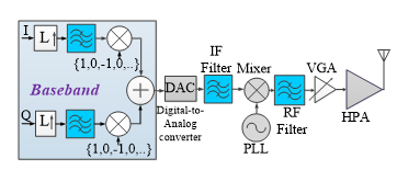
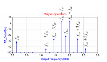
The frequency fIF of the signal at the IF stage is then up-converted to fRF, at the output of the up-converter. In order to reduce the number of required filters, in a multi-standard transmitter, the upper side band signal located in fRF = fLO + fIF and the lower side band signal located in fRF = fLO – fIF are used. The mixing of the IF signal and the carrier produces the desired output signal, the image signal and the intermodulation products. As illustrated in Figure 3, the desired signal can be located either on the upper or lower sideband. Harmonics and inter-modulation products have the form m*fLO+n*fIF, and the critical harmonics are: –fLO+5fIF, fLO–3fIF, fIF, fLO, fLO+3fIF, fLO+5fIF. The IF-frequency fIF is fixed whereas the PLL-frequency fLO is tuned. If the signal is transmitted in the upper sideband, the filer should reject the nearest unwanted signal components fLO and fLO+3fIF. In the same way, if the signal is transmitted in the lower sideband, the rejection of fLO and fLO–3fIF is required. This concept allows increasing the bandwidth of the RF filters, and therefore, it reduces their numbers.
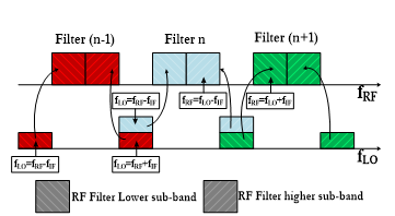
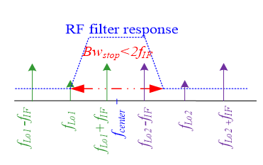
Moreover, it decreases the frequency range that should be covered by the PLLs. Indeed, the sub-frequency band of the PLL that will cover the higher sub-band of the filter will be re-used to cover the lower sub-band of the filter. Figure 4 illustrates this concept. In conventional direct-conversion architecture, the maximum stop bandwidth of a filter is lower than fIF. By using the optimization concept, the stop bandwidth of each RF filter is lower than 2fIF. An overview of this filtering strategy is given in Figure 5. The difference between the upside (fStopHigh) and low side (fStopLow) stop band frequencies of the RF filter should be at most equal to 2fIF. Two scenarios are included in Figure 5, the higher lateral band (fLO1+fIF) is filtered where fLO1 is the frequency generated by the local oscillator. In the second scenario, the lower lateral band (fLO2–fIF) is filtered by the same filter where fLO2 is the frequency generated by the local oscillator.
2.2. Optimization of a Direct Conversion Multi-standard Transmitter
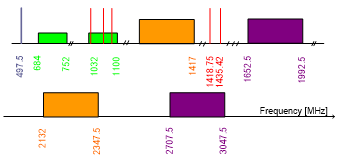
The frequency plan to be covered is shown in Figure 6. The second generation of a cellular communication standard (GSM) offers voice and low speed data transfer [6]. The need to add multimedia services at a very high-speed in wireless communication infrastructure has led to the development of the third generation such as UMTS and the fourth generation as Wimax [7]. Local and Personal wireless networks such as WLAN, Bluetooth and Zigbee have become very popular [8]. And satellite navigation systems were developed to enable precise and reliable positions for users. European Union launched a new positioning system called Galileo and United States of America have upgraded their satellite navigation system [9], [10].
The method consists on subdividing the whole frequency band into sub-bands, respecting the fact that the rejection bandwidth does not exceed 2fIF. Another point that should be considered is that closer the pass band is to 2fIF, the steeper the slope of the filter transfer function has to be. Therefore, the order of the filter increases and the number of resonators increases as well which increases the size of the RF filters. The rejection bandwidth should not exceed 2fIF. Thus, in order to reduce the number of required RF filters, The IF frequency fIF should be high enough.
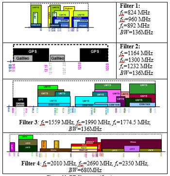
The maximum frequency that the afforded digital to analog converter can generate is 140 MHz. Thus, the transmitter requires 8 RF filters, each one having a bandwidth less than 2 fIF =2×140=280 MHz. the standards served by each RF filter are shown in Figure 7. Filter 1 covers the standards GSM, UMTS and Zigbee between 824 MHz and 960 MHz. Filter 2 covers GPS and Galileo signals. It has a bandwidth of 136 MHz centered at 1232 MHz. Filter 3 covers also GPS and Galileo signals between 1559 MHz and 1575 MHz. Filter 4 covers the standards GSM and UMTS between 1710 MHz and 1785 MHz. Filter 5 covers also the standards GSM and UMTS between 1805 MHz and 1990 MHz. Filter 6 covers the UMTS standard between 2010 MHz and 2170 MHz. Filter 7 covers Wimax, Bluetooth, Zigbee and WLAN standards between 2300 MHz and 2497 MHz. Filter 8 covers UMTS and Wimax standards between 2496 MHz and 2690 MHz.
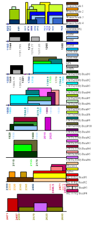
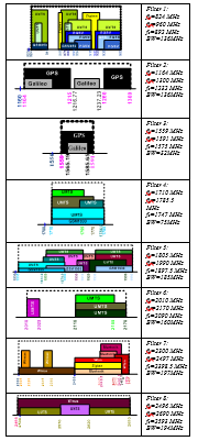
Figure 8 shows how the multi-standard architecture generates and processes the right signal. GPS signal is taken here as an example to illustrate the process. At the DAC output the FPGA generate the GPS signal that passes through an IF filter of 32 MHz bandwidth, centered at 140 MHz. This corresponds to the maximum pass band allowed by the whole set of standards. The filtered signal is then up-converted to the desired RF frequency using a Phase Locked Loop (PLL). A combination of a two digitally controlled SPDT and SP4T switches insures the routing of the signal to the GPS filtering path which is selected among 8 RF filtering arms. Finally, the filtered signal is amplified before transmission.
The frequency band covered by the voltage controlled oscillator used in the PLL depends on RF filter bandwidths. For a given filter having a central frequency fc and a bandwidth BW, the frequency range is:
[ fc–BW/2–fIF ; fc–fIF] if we choose fRF = fIF + fLO, (1)
[ fc+fIF ; fc+ fIF+BW/2] if we choose fRF = fLO–fIF. (2)
Figure 9 shows the obtained frequency ranges to be covered by the frequency synthesizer.
The mixer is selected primarily depending on its frequency band operation. The characteristics of the mixer are shown in Table 1. The frequency band of the LO port has to cover 824 and 2690 MHz. It has to exhibit a high IIP3 and a high 1dB compression point, as well as low insertion loss. Regarding those conditions, the best candidate is MACOM’s ESMD-C50M mixer. For the SPDT switch, many device candidates are possible. The Analog Devices’ ADG918 exhibits the lowest insertion loss and return loss and offers the highest isolation and IIP3. For SP4T, the Analog Devices’ADG904 fulfil the requirements. The specifications of the RF switches are presented in Table 2.
Table 1 Mixer main characteristics
| Mixer Name | MACOM ESMD-C50M |
| RF band [MHz] | 10-2950 |
| IF band [MHz] | 30 – 590 |
| LO band [MHz] | 10 – 2950 |
| Conversion Loss [dB] | 6.21 |
| LO drive level [dBm] | 13 |
Table 2 SPDT & SP4T main characteristics
| Name | SPDT- ADG918 |
SP4T- ADG904 |
| Freq band [MHz] | DC – 4000 | DC-2700 |
| Insertion Loss [dB] | 0.8 | 1.1 |
| Isolation [dB] | 43 | 37 |
| Retun Loss [dB] | 26 | 27 |
| IP1dB [dBm] | 17 | 16 |
| IIP3 [dBm] | 36 | 31 |
The IF filter has to be centered at 140 MHz with a minimum bandwidth of 32 MHz. Low ripple, low insertion loss and low group delay are required. High stop band rejection and return loss are also needed. Oscilent’s 820-IF140.0M is selected as it satisfies all the requirements. Its characteristics are presented in Table 3.
Table 3 IF Filter characteristics
| Name | Oscilent820-IF140.0M |
| Center Freq [MHz] | 140 |
| Bandwidh [MHz] | 34 |
| Ripple (dB) | 0.65 |
| Group delay (us) | 0.96 |
| Rejection (dB) | 60 |
| Insertion Loss (dB) | 22.2 |
The RF filter reponse depends on the characteristics of the chosen RF components, especially the frequency conversion bloc. The rejection level required to attenuate the level of fLO, fLO ± 3fIF and of the other remaining intermodulation products should be determined to respect the out-of-band emission mask. A software simulation (ADS) is used to obtain the level of different harmonics and intermodulation products at the input of RF filters and at the output of the first stage of RF switches.
The common RF filter response is plotted in Figure 10. The attenuation Amin should be low in the filter passband between Fc–Fp and Fc+Fp. The term is the attenuation level needed to reject the oscillator signal. The frequency bands between Fc-Fp– fIF and Fc– fIF and between Fc+ fIF and Fc+Fp+ fIF correspond to the frequency range of the PLL frequency fLO. The term Amax is the attenuation level to be achieved for the image frequency. The frequency bands between Fc-Fp-2fIF and Fc-2fIF and between Fc+2fIF and Fc+Fp+2fIF correspond to the frequency range of the image signal. The term is the minimum level required to attenuate the intermodulation product located in and . The frequency bands between Fc-Fp-4fIF and Fc-4fIF and between Fc+4fIF and Fc+Fp+4fIF correspond to the frequency range of the harmonic components and respectively. The term is the minimum level required to attenuate the harmonics located in and . The frequency bands between Fc-Fp-6fIF and Fc-6fIF and between Fc+6fIF and Fc+Fp+6fIF correspond to the frequency range of the harmonic components and respectively. The term is the attenuation level of the IF component.
Different standards have an attenuation levels depending on the in- and out-of-band emission limits. The level of each harmonic components and undesired signals at the input of the RF filters are designed with a software simulation. The obtained harmonics and intermodulation products rejection levels for each filter are summarized in Table 4. The RF power amplifier is assumed to be linear to guarantee that the levels of the generated harmonics and intermodulation products generated by the up-converter relative to the signal level are kept to be similar after the amplification bloc.
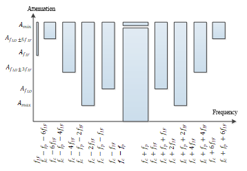
Table 4 FLO and FLO± 3FIF rejections for each channel filter
| Specification | Center Freq [MHz] | Pass band Freq [MHz] | fLO± 3fIF rejection level [dB] | fLO rejection level [dB] |
| Filter 1 | 892 | 136 | 80 | 59 |
| Filter 2 | 1232 | 136 | 40 | 19 |
| Filter 3 | 1575 | 32 | 40 | 19 |
| Filter 4 | 1747.5 | 75 | 80 | 59 |
| Filter 5 | 1897.5 | 185 | 80 | 59 |
| Filter 6 | 2090 | 160 | 53 | 32 |
| Filter 7 | 2398.5 | 197 | 52 | 31 |
| Filter 8 | 2593 | 194 | 53 | 32 |
1.1. Optimization of a Multi-standard transmitter architecture using single/double conversion
The first architecture uses eight RF filters, two SPDT switches, four SP4T switches. This architecture is costly in terms of size. For optimization purposes, we have developed another architecture based on double conversion. Two stages are used to transpose the signal from an intermediate frequency to RF frequency.
In order to reduce further the number of required RF filters, The IF frequency fIF should be sufficiently high. The maximum frequency that the afforded DAC can generate is 140 MHz. The purpose is to cover the maximum standards with the minimum number of filters. The judicious filtering technique detailed in the section II.A is re-used to develop this architecture.
The first part of the spectrum is 824 –1300MHz. For this section of the spectrum, the direct conversion method with an IF frequency of 140 MHz (which leads to a maximum channel filter bandwidth of 280 MHz) gives good results in terms of rejections. However, the second section of the spectrum (1559 – 2690 MHz) requires at least six IF-filters to be entirely covered. To reduce the total size and cost of this previous setting, we use instead, a double conversion with a new IF-frequency that will be high enough to require at most two band-pass filters without being too close to the LO frequency. This prevents to generate harmonic interference.
In fact, the intermediate frequency is not fixed for this architecture, it is chosen in such a way that it does not exceed the third of the frequency of the phase-locked loop, . Indeed, at the output of each mixer at both frequency conversion blocs, the critical harmonics that should be filtered are , , , , , . These harmonics may disturb the judicious filtering technique when one of them, at least, falls within the frequency ranges between and . The RF filter bandwidth is at most equal to twice the intermediate frequency
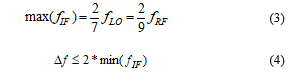
Looking at Figure 6, the frequency bands of interest start at . According to (3), the maximum IF frequency is therefore 206 MHz. In one hand, if the carriers around 824 MHz are generated by double conversion, the maximum of the frequency at the output of the digital converter must be 51.5 MHz. In the other hand, if the signal is generated by direct conversion, the maximum of the intermediate frequency is 140 MHz and the first filter covers the frequency band between 824 MHz and 960 MHz. The bandwidth of the filter is 136 MHz and the minimum intermediate frequency is 68 MHz. The first filter bandwidth covers GSM, UMTS and Zigbee standards. The second filter starts at . According to (3), the maximum IF frequency is therefore 291 MHz in the case of direct conversion. The bandwidth of the filter is 136 MHz therefore the minimum frequency is 68 MHz. The frequency bands to be covered which come just after the second filter start at frequency 1559 MHz. The corresponding maximum IF frequency is 389.75 MHz. The third filter covers the band 1559-1990 MHz. The maximum frequency and minimum frequency is therefore 215.5 MHz. The fourth filter covers the frequency band between 2010 MHz and 2690 MHz. The maximum intermediate frequency is 502.5 MHz and the minimum intermediate frequency is 340 MHz. Simulations using Advanced Design System (ADS) of Keysight technologies on this set up (see Simulation section) prove that the second stage IF frequency of 357.5 MHz is a good compromise and corresponds to a central frequency of an available intermediate filter. The maximum allowed channel filter bandwidth is 715 MHz. The filters 1 and 2 are used for the direct conversion whereas the filters 3 and 4 are used for the double conversion. Specifications of each RF filter are summarized in Figure 11.
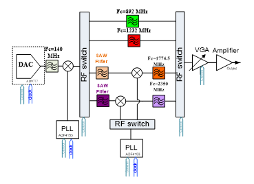
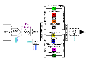
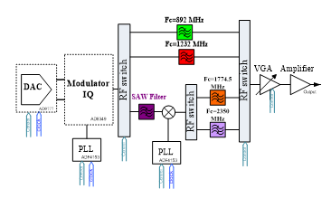
The global transmitter architecture is shown in Figure 12. The DAC output is filtered by an IF-filter with a 32 MHz bandwidth (corresponding to the maximum pass band of the GPS standards) centered at 140 MHz. The signal is then up-converted to a desired RF frequency. Then, depending on the RF frequency, the signal is routed to either single or double conversion path. For the double conversion, two intermediate surface acoustic wave (SAW) filters centered at 357.5 MHz and having at least 32 MHz bandwidth are to be considered before the second up-conversion stage. The signal is then driven by a variable gain amplifier (VGA) depending on the standard and finally amplified by a high power amplifier (PA).
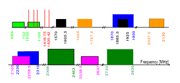
Figure 13 shows the obtained frequency for the local oscillators. The green bands of 684 – 752 MHz and 1032 –1100 MHz are the LO frequencies corresponding to the direct conversion path (filters 1 and 2). For double conversion path we use the up sideband frequency 497.5 MHz (357.5+140) because it is closer to the other required bands. The orange and purple bands corresponds to the LO frequencies of the second PLL for the 3rd and 4th filters respectively (low side band and higher side band).
In the frequency synthesizer’s side, the frequency range to be covered by the Voltage-Controlled Oscillator (VCO) depends on the bandwidth of the filters. For a filter whose center frequency is and the bandwidth is , the frequency range to be covered by the VCO is between and on the one hand and between and on the other hand. Figure 13 shows the total frequency range to be covered by the RF frequency synthesizers. For the signals covered by the first two filters covering the frequency bands 824-960 MHz and 1164-1300 MHz respectively, the intermediate frequency is set to 140 MHz. In the path where the frequency transposition occurs twice, the intermediate frequency at the output of the analog-digital converter is fixed and is equal to 140 MHz. The signal generated by the converter is transposed to 357.5 MHz by the first block of the frequency synthesizer. The first frequency synthesizer should generate a frequency of 497.5 MHz or 217.5 MHz. The frequency 497.5 MHz is chosen because it is closer to the other frequency ranges. The second block of the frequency synthesizer serves to transpose the 357.5 MHz frequency signal to a RF signal that will be filtered by the third and fourth filters.
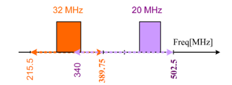
Between the two mixers, a filter should be inserted. In the market, SAW (Surface Acoustic Wave) filters can be used. The third filter covers GPS, Galileo, UMTS, GSM and WLAN standards with a maximum channel width of 32 MHz. The fourth filter covers the UMTS, WIMAX, Bluetooth, Zigbee and WLAN standards with a maximum bandwidth of 28 MHz. The first and the second SAW are pass-band filters. The center frequency of the first SAW is located between 215.5MHz and 389.75 MHz and between 340 MHz and 502.5 MHz, for the second. Their bandwidth should be at least 32 MHz and 20 MHz respectively. Figure 14 illustrates the possible locations of IF channels to be filtered by the third and fourth filters, i.e, at the second frequency conversion bloc.
The folding of the two intermediate frequency ranges is considered as an optimization point if a filter that covers the frequency band between 389.75 MHz and 340 MHz is available. From the market, the chosen SAW filter is RFM SF2090C as its ripple, group delay and insertion loss are low and its out-of-band rejection is high. Its characteristics are in Table 5.
The modified transmitter architecture is illustrated in Figure 15. The transmitter includes an analog to digital converter, a mixer, phase locked loops, an SPDT type RF switch, two SP4T type RF switches, a variable gain amplifier and an RF amplifier block. The chosen mixer is MACOM’s ESMD-C50M. Its main characteristics are listed in TABLE I. The RF switches ADG918 and ADG904 of analog devices are the best candidates. Their characteristics are in TABLE II. After the DAC, the IF filter (Oscilent’s 820-IF140.0M) is inserted. Its characteristics are listed in Table 1.
Table 5 SAW IF filter characteristics
| SAW filter Name | RFM SF2090C |
| Center freq [MHz] | 357.5 |
| Bandwidth [MHz] | 35 |
| Ripple [dB] | 1 |
| Group delay [ns] | 55 |
| Rejec-tion [dB] | 40 |
| Insertion Loss [dB] | 12 |
| Frequency Band [MHz] | 340-375 |
The out-of-band attenuations of the first second filters are determined based on the level of the harmonics at the output of the first mixer and the values of the center frequency and bandwidth. The center frequency of the first filter is 892 MHz, and its bandwidth is 136 MHz. The first filter covers GSM, UMTS and Zigbee standards. According to their various masks and spurious emissions cited, the rejection of the image frequency should be 80 dB and of the local oscillator should be 19 dB. The second filter covers the GPS and Galileo systems, the rejection of the image frequency should be 40 dB and of the component is 19 dB. For the third filter and the fourth filter, the levels of harmonics are obtained by carrying out a harmonic balance simulation. The level of harmonic components and is 10.79 dBm. The level of the local oscillator signal is -19.64. According to the Mask signal and out-of-band emission limits of GSM, UMTS, GPS and Galileo, the third filter should attenuate the image signal by 80 dB and the local oscillator component by 71.15 dB. The stop band of this filter is 720 MHz. The fourth RF filter has a bandwidth of 680 MHz. It covers UMTS, Bluetooth, Zigbee, WLAN and WIMAX standards. It should attenuate the signal at by 44.15 dB and the image frequency by 53 dB.
3. Simulation
3.1. Simulation of the Direct Conversion Multi-standard Transmitter
To validate the concept, the multi-standard architecture is implemented in ADS, as shown in Figure 16. The RF filters, the RF switches, the mixer as well as the IF filter are implemented by using their models. The simulation allows checking whether the spurious signals are well rejected by the RF filters. All standards generated through the proposed multi-standard architecture are tested. And for each standard, many frequency step simulation runs were carried out. The output spectrum respects the out of band emission limits, in all simulated cases. The following test run is used as an illustration example.
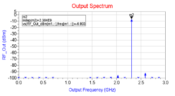
To generate a WiMAX signal at 2304 MHz, the RF switches are activated in a way that the signal is filtered by filter 7. The frequency of the signal that is generated by the PLL is . The spectrum of the signal at the output of the transmitter for this case is illustrated in Figure 17.
3.2. Simulation of a multi-standard transmitter using single/ double conversion technique
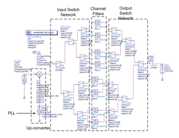
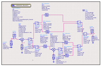
After the selection of the RF components, the simulation of the second architecture is done using the Keysight–ADS simulator. The circuit diagram useful for completing the simulation in ADS is shown in Figure 18. The simulation consists in carrying out the spectral analysis at the output of the transmitter by varying the frequencies of the frequency synthesizers and adjusting the control parameters of the RF switches.
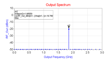
For example, if the frequency of the first frequency synthesizer and of the second frequency synthesizer are adjusted to and . The different RF switches are tuned in a way that the RF signal passes through the third filter. At the output of the transmitter, the spectrum is shown in Figure 19.
4. Conclusion
In this paper, two new optimized architectures of a multi-standard transmitter have been presented. The first one is an heterodyne based architecture. The second combines single and double frequency conversion that allows further reducing the cost, size and weight of the transmitter. This transmitter is a part of a wireless radio that will be carried by an UAV reaching stricken areas after a disaster and therefore enabling and making easier efficient rescue intervention.
It has been shown, through simulation, that both of architectures can generate GPS and Galileo signals which are very critical for rescue operations and waveforms of different cellular wireless communication standards (UMTS, GSM and Wimax) along with waveforms of different local and personal area wireless network standards (Bluetooth, Zigbee and IEE802.11 b/g). The high number of different wireless communication standards and their operating frequency bands requires a high number of RF filters and PLLs. The first architecture is direct conversion. It uses an analog digital converter to convert the digital signal into an analog signal. The analog signal passes through an IF filter with a center frequency of 140 MHz. The filtered signal is mixed with a carrier to be transposed to an RF frequency. The RF signal may be the upper or lower sideband. The RF signal passes through an SP4T switch which points the RF signal to its corresponding RF filter. The first architecture uses eight RF filters. RF filters are partitioned and defined based on the judicious filtering technique. For each RF filter, the lower half of bandwidth serves to filter the upper side signal and the upper half of filter’s bandwidth serves to filter the lower side signal. The second architecture is less expensive than the first. It uses fewer components. It uses two SAW IF filters, two mixers, two SP4T RF switches, an SPDT RF switch and four RF filters. The frequency range to be covered by the frequency synthesizers of the second architecture is between 497.5 MHz and 3047.5 MHz. As a logical perspective, the architecture can be further optimized. There is an opportunity to use a frequency doubler that allows using fewer RF filters and fewer RF frequency synthesizers.
- F. Gagnon, “La radio cognitive, l’avenir de demain,” ed, May 2013.
- S. M. Mollenkopf, P. H. A. See, and B. C. Walker, “Multi-standard transmitter system and method for a wireless communication system,” ed: Google Patents, 2005.
- H. Jensen, “Translational Loop RF transmitter architecture for GSM Radio,” United States Patent, vol. US007386283B2, no. Broadcom Corporation, p. 14, Jun. 10,2008 2008.
- J. Kilpatrick, J. Dawson, J. Bohorquez, and J. Venuti, “Programmable transmitter architecture for non-constant and constant envelope modulation,” ed: Google Patents, 2007.
- R. Essaadali, T. Hadouej, C. Jebali, and A. Kouki, “Optimization of a direct conversion multi-standard transmitter used for rescue operations,” in MILCOM 2016 – 2016 IEEE Military Communications Conference, 2016, pp. 1173-1178.
- L. Harte and Books24x7 Inc. (2005). Introduction to global system for mobile communication (GSM) physical channels, logical channels, network, and operation [Text.].
- J. G.Andrews, A. Ghish, and R. Muhamed, Fundamentals of WiMAX Prentice Hall, february 2007.
- H. A. H. Labiod, C. De Santis. (Springer, 2007). WI-FI TM, BLUETOOTH TM, ZIGBEE TM AND WIMAX TM.
- A. R. CORPORATION, Navstar GPS Space Segment/Navigation User Interfaces, 1993.
- J. Kreher, “GALILEO Signals : RF Characteristics,” presented at the Navigation System Panel, 2004.