The Analysis and Comparison of Multiport Converter used for Renewable Energy Sources

Adv. Sci. Technol. Eng. Syst. J. 2(3), 906–912 (2017);
 DOI: 10.25046/aj0203113
The concept of renewable energy is increasing day by day because the electrical applications are moving towards utilization of renewable sources and due to this factor electric power is also gaining ground and new type of converters are modelled in order to get high utilization of renewable sources. In this paper, two types of multiport converters are presented which includes a DC-DC converter with a transformer attached and a DC-DC converter without a transformer. The converter with transformer is further subdivided into a full bridge and a half bridge DC-DC converter. The simulation results for all converters are presented and in the end, a case is taken for comparison which involves fixed resistance. The converters are compared with a constant load resistance of 70 ohms in terms of cost, area, complexity, control, isolation, weight and efficiency etc.
1. Introduction
There is an increased trend in the use of multiport converters because of the demand for renewable energy. Electrical applications are moving towards the utilization of renewable energy due to which research in electrical power electronics has increased. With the advancement in renewable energy usage, the DC-DC converter research has also increased and hence multiport converters are being proposed. The multiport converter helps in interfacing multiple sources at a time and delivers power from sources to load simultaneously as well as separately.
In [1] a review of multiport converter is presented. The multiport converters presented in [1] comprises of converters with the transformer attached and detached. The converter with the transformer attached is further subdivided in to Half Bridge Three Port (HBTP) DC-DC Converter and Full Bridge Three Port (FBTP) DC-DC Converter. The advantages and disadvantages of each converter type for each DC-DC converters are presented.
This proposed paper is an extension of [1] where the multiport converters were analyzed at constant load resistance of 70 ohms for each case and they are compared in terms of losses within the converters, area of the converters, cost of converters, controlling of converters and complexity of converters etc.
In [2] an overview is presented regarding multiport converters. The first section contains the information of multiport converter introduction. In the second section, a comparison between the multiport converter and conventional converter is presented.
The conclusion of research involves; every dc-dc converter has its own advantages and disadvantages so it depends upon the applications for which the converter is to be used. In the case of isolation, converters with transformers are to be used while if the isolation is not required then DC-DC converters without transformers are to be used.
In [3] a dc-dc converter topology is presented which has the following advantages:
- Simplification of power conditioning
- Improved utilization of source
- The ports of converter supports bidirectional power flow
| *Sarab Al-Chlaihawi, Ph.D. student, University Politehnica of Bucharest, 060042, Romania, +40723062504, sarab.haedar@yahoo.com |
- Each port can be controlled individually
- The connected sources of current can be decoupled
With this converter, we can control the level of every individual delivery of power and decouple the associated source of the current in series sources.
In [4] different types of DC to DC converters are used and their computational performances are analyzed along with their efficiencies. The Buck converter gives better computational performance and a high efficiency with the resistance lesser than Resistance at the maximum power point (RMPP) but a low efficiency with the Resistance greater than the RMPP. The Boost converter gave a low computational performance and a low efficiency with the Resistance less than RMPP but a high efficiency with the Resistance greater than RMPP. Similarly, the Buck-Boost converter gave a better computational performance and a high efficiency with the Resistance less than RMPP along with a high efficiency with the Resistance greater than RMPP.
The Cuk converter gave an average computational performance with a medium efficiency with the Resistance less than RMPP but a high efficiency with the Resistance greater than RMPP. The SEPIC converter also gave an average computational performance with a medium efficiency with the Resistance less than RMPP but a high efficiency with the Resistance greater than RMPP while the Zeta Converter gave a better computational performance with a medium efficiency with the Resistance less than RMPP but a high efficiency with the Resistance greater than RMPP.
From the above discussion it can be concluded easily that the buck-boost converter is suitable for Maximum Power Point Tracker (MPPT) because its efficiency is higher in both cases whether the resistance is greater than RMPP or less.
In [5] multiport converters are discussed. The converters are compared in terms of soft switching and isolation. In the conclusion of [5] the advantages and disadvantages of a multi-port dc-dc converter are presented. These are:
- utilization of two or moresimultaneous power sources
- lower cost due to semi-conductor elements and fewer passive components
- the power to load can be in higher productions because of multiple sources
- the management of energy can be monitored in a better way
In [6] the comparative study of MPPT algorithm is presented. The MPPT algorithm is used by the controller to get maximum power from the PV panel.
The algorithms presented for comparison are based on Fuzzy Logic for MPPT controller, Incremental Conductance and Perturb & Observe (P&O). The algorithms are tested in standard conditions with atmospheric condition variance. The results obtained are:
- The response of Incremental Conductance algorithm is better at a steady state but it has some errors when compared to the Perturb & Observe algorithm.
- In Perturb & Observe algorithm there is some oscillation at the operating point which results in loss in available power thus PV module efficiency is decreased.
- In Perturb & Observe algorithm the MPP tracking is directly proportional to the step size of perturbation.By higher stepsthe Maximum Power Point (MPP) is achieved faster but then there are oscillations at steady state.
- The Fuzzy Logic controller provides a better steady state and transient state performance as compared to classical methods. Fuzzy Logic controller tracks MPP with high speed and it has more stability at the steady-state in comparison with Perturb & Observe algorithm and Incremental Conductance algorithm.
For different types and capacities of renewable energy sources, an isolated multiport DC-DC converter is proposed in [7] for its corresponding simultaneous management of power. Only one controllable switch is utilized for each port in which a source is connected. As a result, it has a very limited number of power switches and a very simple topology. The proposed converter’s operation and characteristics are explained and analyzed and its applications are discussed.
In order to replace the regular transformer distribution, a solid state transformer (SST) is proposed in [8] which helps enables the formation of power quality features along with providing ports for the integration of the distributed generation (DG) (e.g. photovoltaic (PV)) as well as storage. A quad-active-bridge (QAB) converter based on SST topology is modelled in [8] which facilitates the load isolation along with the isolation of the distributed generation as well as the storage. An average model formulated on the gyrator is developed which helps facilitates a general multi-active-bridge (MAB) converter. Using these expressions, the power ratings of the MAB ports are derived. These results are then applied onto the QAB converter and later on it is analyzed.
For a stand-alone renewable power system application, a systematic strategy is proposed in [9] in order to interface a renewable source, a load and a storage battery with the generated Three-Port Half-Bridge Converters (TPHBCs). If the DC bias current is allowed in the transformer then the half-bridge converter’s primary circuit operates as a rectified synchronous buck converter which can help configure a power flow path between the battery and the renewable source which are, as a result, connected in parallel with one of the dividing capacitors. A post and a synchronous regulation has been proposed for various implementations in order to make the voltage on any two of the ports individually controlled.
A three-port converter (TPC) derived from a full-bridge converter (FBC) is proposed in [10] and its systematic approach has been discussed. The methodology helps strips a pair of the switching legs of the corresponding FBCs into two different switching cells with distinct sources attached to it and along with this a DC bias current is also allowed in the transformer. By utilizing the proposed strategy, a full-bridge TPC (FB-TPC) is developed for the applications of the renewable power systems which composes of multiple characteristics which includes: a single-stage power conversion between any two of the three ports, reduced number of devices, an easy and understandable control method and topology.
A three-port DC-DC converter which integrates the photovoltaic (PV) and the power of the battery for a high step-up applications is proposed in [11] in which the topology comprises of two coupled inductors (they help to acquire high step-up voltage gain and also help reduces the voltage stress produced by the two input switches), two active-clamp circuits (which helps recycles the energy which is stored in the leakage inductors and also improves the efficiency of the system) and five power switches. The operation mode does not require changing in case a transition between the discharging and charging occurs.
The major contribution of the proposed paper is to analyze multiport converters at constant load resistance of 70 ohms for each case and after that, they are compared in terms of losses within the converters, area of the converters, cost of converters, controlling of converters and complexity of converters etc. So this paper is organized as follows:
- Section 2 explains in detail about the Half bridge and Full bridge converters.
- Section 3 discusses the Dual Input Single Output converter (DISO).
- Section 4 is detailed with the comparison between a converter with a transformer and a converter without a transformer.
- Section 5 contains the in depth analyses of the results.
- And at the end in Section 6, the conclusion has been given.
2. Half Bridge Converter and Full Bridge Converter
In the above section, the literature about Multiport converters has been presented. According to the literature the multiport converters have resolved the problems of single input converters and improved the renewable energy interfacing.
The interfaced sources in the multiport converter can be unidirectional or bidirectional and the sources are able to deliver power to load individually and simultaneously. By the use of multiport converters, components are reduced hence cost is reduced, while reliability and power are increased.
The characteristics of multiport converter in comparison with traditional converter are:
- It has a high efficiency.
- It is more reliable.
- It has less number of components but complexity increases.
- Insulation can be attained by adding transformer.
- It supports unidirectional as well as bidirectional power flow.
- It has more control area.
- It has flexibility.
2.1. Operation of converter
Figure 1 shows the half bridge single phase converter. It is composed of two switches (out of which the mostly used switch is MOSFET) and two capacitors, one with source and one with load.
The flow of power inside the inverter varies after every half cycle.
Let the source voltage be ‘Vs’ for half bridge converter and switching frequency be ‘f’ and ‘T’ be the total time of the whole cycle.
![]()
For time the power flow path is through MOSFET ‘S1’ and capacitor ‘C2’. The voltage obtained at load ‘VL’ is
![]() For time the power flow path is through the MOSFET ‘S2’ and capacitor ‘C1’. The voltage obtained at load ‘VL’ is
For time the power flow path is through the MOSFET ‘S2’ and capacitor ‘C1’. The voltage obtained at load ‘VL’ is
![]() It can be seen that the magnitude of ‘VL’ is half as half of the voltage is dropped across the capacitor.
It can be seen that the magnitude of ‘VL’ is half as half of the voltage is dropped across the capacitor.
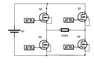 Figure 1: Half Bridge Converter
Figure 2 shows the full bridge single phase converter. It is composed of four switches (of which the mostly used switch is MOSFET), with source and load. The flow of power in the inverter varies after every half cycle.
Let the source voltage for the full bridge converter be ‘Vs’ and switching frequency is ‘f’ and ‘T’ be the total time of the whole cycle.
 For time the power flow path is through MOSFET ‘S1’ and MOSFET ‘S4’. The voltage obtained at load ‘VL’ is
![]() For time the power flow path is via MOSFET ‘S2’ and MOSFET ‘S3’. The voltage obtained at load is ‘VL’
For time the power flow path is via MOSFET ‘S2’ and MOSFET ‘S3’. The voltage obtained at load is ‘VL’
![]() It can be seen that the magnitude of the voltage at output ‘VL’ is increased in comparison to the half bridge converter because half of the voltage which dropped across the capacitor is now retrieved by using switches instead of capacitors.
It can be seen that the magnitude of the voltage at output ‘VL’ is increased in comparison to the half bridge converter because half of the voltage which dropped across the capacitor is now retrieved by using switches instead of capacitors.
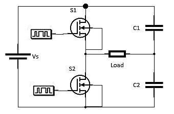
Figure 2: Full Bridge Converter
The half bridge converter limitation is overcome by using the full bridge converter. So with the help of the full bridge converter, the output voltage is increased.
3. Dual Input Single Output
The dual input single output (DISO) DC-DC converter shown in Figure 3 is presented in [1]. It is a DC-DC converter without a transformer. The converter is composed of one inductor, two capacitors and four switches.
The advantage of this converter is the controlled flow of power between the input and the output. The two input sources are, the unidirectional battery and the PV panel. The use of the battery is to provide power to the load side.
The PV panel is used as a primary source for utilization of the renewable energy while at the secondary source; the battery delivers the power when there is a power reduction from the solar system.
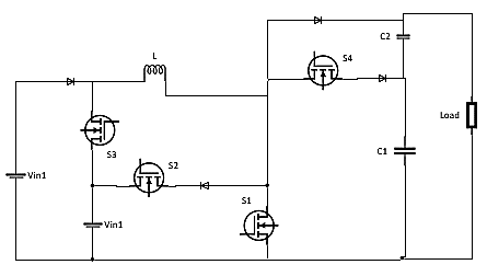 Figure 3: Dual Input Single Output Converter
4. Comparison between Transformer and Transformer-less Multiport Converter
Both the systems, with a transformer and without a transformer, delivers power but with some specifications whether a transformer is required or not in an application, depends on the particular application.
4.1. With transformer
A transformer is used in any of the applications listed below:
- For step up of voltage.
- For step down of voltage.
- For creation of either magnetic or galvanic isolation.
- For reduction of transformer current, Delta-wye transformers should be used.
- Fault current can be restricted.
- For obtaining multiple output voltages, taps in the transformer can be used.
There are also some disadvantages in using transformers:
- Cost increment
- Area increment
- Weight increment
- Reduction in Efficiency
4.2. Without transformer
In comparison to a system with a transformer, the system without a transformer also works, and it has some unique characteristics as well:
- Reduction in Cost
- No heavy circuitry
- Reduction in Weight
- Reduction in number of components
- Efficiency increment
- Fast Response
Some disadvantages of system without transformer are:
- Isolation is not present
- The level of voltage remains the same
- No taps availability as in the case of the transformer
5. Results
5.1. Half Bridge converter
Figure 4 displays the output voltage of the half bridge converter. It can clearly be seen from the graph that the output voltage reaches a maximum magnitude of 19 V after which it stabilizes steadily.
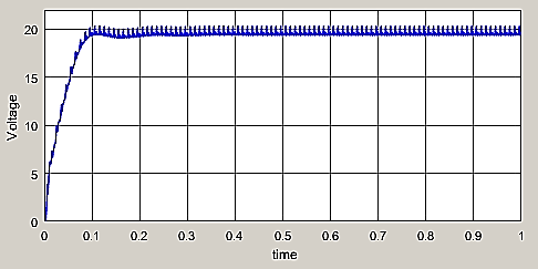 Figure 4: Half Bridge Converter Output Voltage
There is an overshoot produced at 0.1seconds but till 0.2 seconds the voltage stabilizes completely. The ripples produced in the output are due to the capacitor of a smaller magnitude being used. If the value of capacitor is increased the output stabilization time will be high.
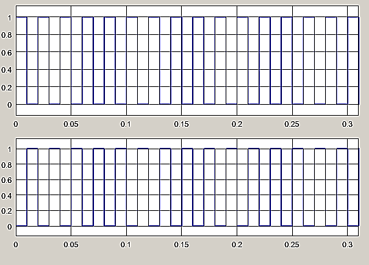 Figure 5: Half bridge Converter Switches Signals
The states of the switches has been displayed in Figure 5, where the first signal displayed has been provided to switch ‘S1’ while its inverted wave that is displayed in the second signal in Figure 5 is for the switch ‘S2’.
This means that while the switch ‘S1’ is ON, ‘S2’ will remain OFF and vice versa. Similarly, the same case is observed for the remaining bridges in the converter.
5.2. Full Bridge Converter
In Figure 6, the voltage at the output of the full bridge converter is displayed. It is observed that the voltage can be stabilized at around 190 V till 0.02s with the help of high capacitances.
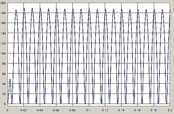 Figure 6: Full Bridge Converter Output Voltage
The produced ripples in the output voltage are a result of using capacitors with small magnitudes. If the magnitude of the capacitors is increased, the output time taken for the converter to stabilize would increase.
The switching signals provided to the H-bridge have been represented in Figure 7. The four signals (from top to bottom) are being provided to the four switches from ‘S1’, ‘S2’, ‘S3’ and ‘S4’. For controlling on side of the H-bridge ‘S1’ and ‘S3’ are used while ‘S2’ and ‘S4’ are used for controlling the other end of the H-bridge. It can be viewed that while ‘S1’ (signal waveform 1) is switched ON, ‘S3’ (signal waveform 3) remains OFF and vice versa while when ‘S2’ (signal waveform 2) is switched ON, ‘S4’ (signal waveform 4) remains OFF during that interval and vice versa.
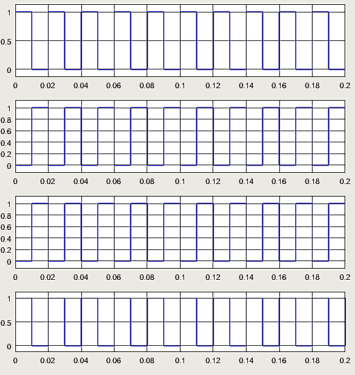 Figure 7: Full Bridge Converter Switches Signals
5.3. Dual Input Single Output
The result obtained at fixed resistance of 70 ohm for all three converters are shown in the table below.
Table: Voltage at inputs and output of multiport DC-DC converter
| Type of Converter | Source 1 (V) | Source 2 (V) | Output Voltage (V) |
| DISO converter (without transformer) |
20 |
20 |
39 |
| FBTP DC-DC converter (with transformer) |
34.5 |
50 |
400 |
| HBTP DC-DC converter (with transformer) |
34.5 |
50 |
152 |
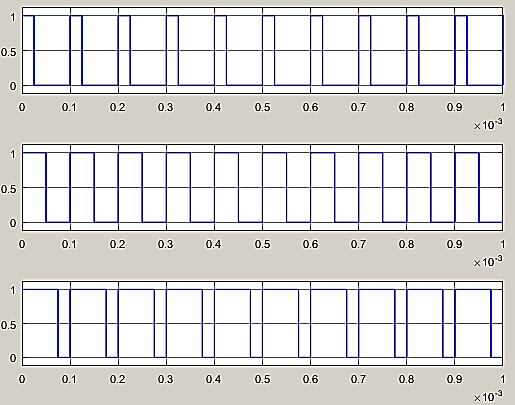 Figure 8: Dual Input Single Output Converter Switches Signals
Figure 8 represents the switching pulses for Dual Input Single Output converter while Figure 9 displays the output voltage for the same DISO converter.
It can be seen from Figure 8 that the switching frequency has been altered a bit for all the three switching signals to a ratio of 0.25%.
The first switch remains ON for 0.25% while the second switch remains ON for 50% and the third one remains ON for 75% for the same time interval (that is from 0 to 0.1ms).
The final output of this converter is displayed in Figure 9, which reaches a maximum of 57V in the overshoot and later on stabilizes at 39V. The time taken for the converter to stabilize in 0.3s.
The efficiency of this converter is quite high compared to the other remaining converters but its major drawback is that one user cannot alter the voltage level in this converter.
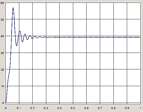 Figure 9: Dual Input Single Output Converter Output Voltage
It can be seen from the above Table that the voltage level of Dual input single output converter remains the same as it is nearly equal to the input source’s voltage. The result obtained shows that it is a highly efficient system as losses are very low in this converter. It has a low cost because less number of components are involved in it.
The ripples in the output are very low and the harmonics are not present in this converter. The structure of this converter is quite simple and easy to implement but its control strategy is a complex task.It can be seen from the Table that the input voltage level of the three port full bridge converter is increased. The output result is almost 12 times higher than the input voltage level.
This converter is not efficient as compared to the DISO converter and its cost is higher. The advantage of this converter over the DISO converter is that the voltage level can be increased or decreased as per requirement. The harmonics are less compared to the half bridge converter but the ripples produced in the output are high.
The structure of this converter is complex but its controlling strategy is simple. A little complexity is to cater the switching time of the transistors or switches, so that all the four switches can work properly. It can be seen from the Table that the voltage level of the three port half bridge converter is increased.
The output result is 4.4 times higher than input voltage level. This converter is less efficient compared to the above two converters and its cost is high. In this converter, the efficiency is very low because of high losses in the converter.
The harmonics produced in the output is high and the ripples are also high compared to the full bridge converter. The structure of this converter is not simple but control is quite easy, as only two switches are involved. When one switch is open, the other switch is closed and vice versa.
6. Conclusion
In this paper, multiport converters are discussed. The converters are of different types and a comparison between the converters is presented on the basis of the multiport converter with a transformer and without a transformer. The multiport converters presented in research are divided into two groups. One with a transformer converter and the other without a transformer converter. The converters with transformer are further subdivided into two parts.
- Full Bridge Three Port DC-DC Converter
- Half Bridge Three Port DC-DC Converter
The advantages of the converter with a transformer are: It steps-up or steps-down the voltage level, provides isolation between the input and output sides, the transformer current can be reduced by Delta-wye transformers, fault current is reduced by impedance, magnetic isolation can be attained and by the taps in transformer we can attain multiple voltages in the output.
The disadvantages of the converter with a transformer are: efficiency reduction, in some cases weight is increased; area increment of converter is also present while the cost also increases. The harmonics components are greater due to the transformer and it has a complex structure (whereas its control is quite easy). Now moving towards the converters without a transformer. The transformer-less converter presented was the Dual Input Single Output converter.
The advantages of the transformer-less converter in comparison to the converter with transformer are: it has a reduced cost factor, less components are used so the area of circuit is reduced. The harmonics are very low and its efficiency is high due to low losses in the converter since the output voltage (39V) is almost equal to the input source voltages (20V each). Its structure is easy to implement.
The disadvantages of transformer-less converter in comparison with the converter with transformer are: only a single level of voltage is obtained, there is no magnetic isolation or galvanic isolation between input and output side, the fault current in not affected as there is no transformer present. The control of this converter is difficult because we have to control more than two pulses at a single time (Source 1 and Source 2).
The complete research work concludes that; every DC-DC converter has its own advantages and disadvantages, so it depends upon the application for which the converter is to be used. For example if we need to change the voltage level, we have to use a converter which contains a transformer while in the case when voltage level change is not required we can use a transformer-less converter.
Acknowledgment
I, personally, thank the Iraqi government represented by the Ministry of higher education and scientific research, Al-Furat Al-Awsat Technical University, Najaf, Iraq for its financial support.
- Al-Chlaihawi, S. J. (2016, October). Comparative study of the multiport converter used in renewable energy systems. In Applied and Theoretical Electricity (ICATE), 2016 International Conference on (pp. 1-6). IEEE.
- AL-Chlaihawi, S. J., & Al-GIZI, A. G. (2016, June). A survey of multiport converters used in renewable energy. In Fundamentals of Electrical Engineering (ISFEE), 2016 International Symposium on (pp. 1-4). IEEE.
- Hawke, J. T., Krishnamoorthy, H. S., & Enjeti, P. N. (2014, September). A multiport power sharing converter topology for renewable-to-grid interface. In Energy Conversion Congress and Exposition (ECCE), 2014 IEEE (pp. 4992-4999). IEEE.
- Ramki, T., & Tripathy, L. N. (2015, January). Comparison of different DC-DC converters for MPPT application of photovoltaic system. In International Conference on Electrical, Electronics, Signals, Communication and Optimization (EESCO) (pp. 1-6).
- Khosrogorji, S., Torkaman, H., & Karimi, F. (2015, February). A short review on multi-input DC/DC converters topologies. In Power Electronics, Drives Systems & Technologies Conference (PEDSTC), 2015 6th (pp. 650-654). IEEE.
- Al-Gizi, A. G., & Al-Chlaihawi, S. J. (2016, June). Study of FLC based MPPT in comparison with P&O and InC for PV systems. In Fundamentals of Electrical Engineering (ISFEE), 2016 International Symposium on (pp. 1-6). IEEE.
- Zeng, J., Qiao, W., Qu, L., & Jiao, Y. (2014). An isolated multiport DC–DC converter for simultaneous power management of multiple different renewable energy sources. IEEE journal of emerging and selected topics in power electronics, 2(1), 70-78.
- Falcones, S., Ayyanar, R., & Mao, X. (2013). A DC–DC multiport-converter-based solid-state transformer integrating distributed generation and storage. IEEE Transactions on Power Electronics, 28(5), 2192-2203.
- Wu, H., Chen, R., Zhang, J., Xing, Y., Hu, H., & Ge, H. (2011). A family of three-port half-bridge converters for a stand-alone renewable power system. IEEE Transactions on Power Electronics, 26(9), 2697-2706.
- Wu, H., Sun, K., Chen, R., Hu, H., & Xing, Y. (2012). Full-bridge three-port converters with wide input voltage range for renewable power systems. IEEE Transactions on Power Electronics, 27(9), 3965-3974.
- Chen, Y. M., Huang, A. Q., & Yu, X. (2013). A high step-up three-port dc–dc converter for stand-alone PV/battery power systems. IEEE Transactions on Power Electronics, 28(11), 5049-5062.