A Design of SDN Based IP Mobility Management Considering Inter-Domain Handovers and Its Evaluation

Adv. Sci. Technol. Eng. Syst. J. 2(3), 922–931 (2017);
 DOI: 10.25046/aj0203116
To use IP services continually while users are moving with their mobile devices, IP mobility management that enables them to keep IP communication is necessary. Although Mobile IP is a popular method to manage IP mobility, Mobile IP has a problem that there is a possibility of a mobile node (MN) communicating over a redundant route. Then, Software Defined Network (SDN) based IP mobility management has emerged to solve this problem. Most of these solutions focus on intra-domain handovers and routing. However, since wireless network environment has spread, mobile devices move across domains during communication. To deal with this, we need to look upon inter-domain handovers and routing. In this paper, we propose a SDN based IP mobility management scheme considering situation of mobile devices moving across domains. This proposed scheme focuses on inter-domain handovers and introduces efficient functions of management information sharing and inter-domain routing. Experimental results show the desired effects of the proposed scheme: optimizing communication route and keeping the management information exchange traffic low.
1. Introduction
1.1. Background and Overview
Mobile IP is one of the IP mobility management standardized by Internet Engineering Task Force (IETF) [4-6]. Mobile IP is a technology to enable continuous communication when a MN moves during a communication. Even when a MN moves to a different domain, it enables the MN to continue its communication with the IP address that it was using before the movement. However, there are cases that a MN’s communication route falls into a triangular routing. This might lead to a degrade in quality of service caused by communication delay. Moreover, it is necessary for a MN to be equipped with Mobile IP function, and this leaves a challenge of application to all MNs.This paper is an extension of work originally presented in 2016 18th Asia-Pacific Network Operations and Management Symposium (APNOMS) [1]. Due to the widespread of wireless network environment, it is now possible to use Internet services in various places and scenes, and IP services like file transfer service, remote terminal service, and virtual desktop service are popularly used [2,3]. These services can be used with small-sized devices capable of wireless communication like laptop PCs, smart phones, tablet PCs. We call them mobile node (MN) from now on. MNs are portable, thus people tend to move around while using IP services with MNs. Especially with session continuous IP services, continuity of service during movement may be a problem. When a MN moves and connects to an access point in a different network domain, MN’s IP address may change. If MN’s IP address changes during communication and communication session is disconnected, this causes some problems that would affect the use of services may occur such as lack of data and logout from services. Thus, IP mobility management is essential for enabling use of IP services while moving.
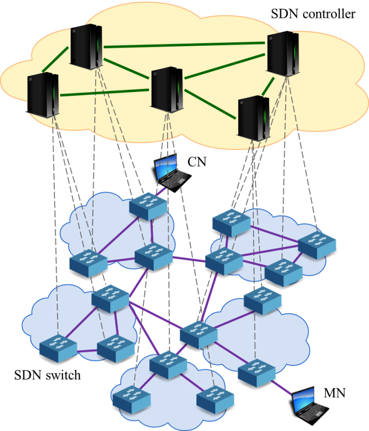
There are some researches that apply Software Defined Network (SDN) to IP mobility management to solve the problems mentioned above [7,8]. SDN is a technology to control a network dynamically with a software [9]. We show an overview of SDN in Figure 1. By using SDN, a SDN controller centrally manages SDN
|
|
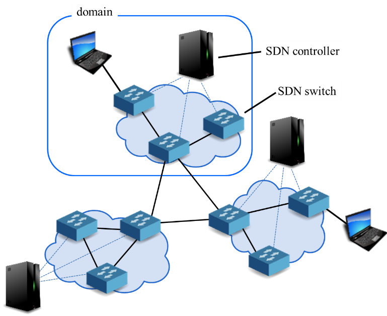
switches in their domain and this enables nodes to communicate with suitable route. However, existing researches focus on intra-domain move. To cope with inter-domain movement with SDN, SDN controllers in different domains have to exchange information about movement of a MN. On this occasion, communication cost between SDN controllers may increase and it might become a problem in practical use. Therefore, it is difficult to maintain communication efficiently when a MN makes an inter-domain move.
There were two major trends in ways to handle inter-domain handover with SDN. One approach is to use Mobile IP when inter-domain handovers occurs [8]. By using Mobile IP, SDN controllers doesn’t need to search for domains to exchange information of MNs. However, Mobile IP has difficulty in communication route optimization. Another is to announce information of MNs to every controllers in the network [7]. This approach allows the communication routes to be optimized. However, with a network consisted of many domains, communication for the announcement might compress the communication bandwidth. These conventional approaches could only realize efficient data exchange or route optimization.
To overcome both of the problems, we propose an SDN based IP mobility management scheme considering inter-domain handovers. Our proposed scheme consists of two functions. The Management Information Sharing Function (MISF) searches a destination domain of a moved MN effectively and chooses minimum SDN controllers to share minimum information related to MN’s communication to manage information efficiently. The Inter-domain Routing Function (IDRF) calculates an appropriate route to allow the MN to continue effective communication.
We also conducted some simulation experiments to confirm the effectiveness of our proposed scheme. The simulation results show that our proposal achieved to optimize communication route and keep traffic between SDN controllers low.
1.2. Novelty and Contribution
To realize efficient inter-domain handovers, we propose a novel scheme to efficiently exchange MNs’ information between SDN controllers in each domains and optimize communication route between a MN and a CN. Existing approaches don’t realize these two requirements simultaneously because these approaches differ in target, purpose and assumed environment therefore they do not match the purpose of what we concentrate on this time. At the time Mobile IP emerged, route optimization had little meaning because there were not so many candidates of route to be selected. Moreover, it aimed for easy implementation without any modifications in network infrastructure, as it focused on practical use so Mobile IP doesn’t have full support to route optimization. The SDN based methods don’t aim at covering wide area network and they are approaches for environment with some limitation on scale. Hence they can handle inter-domain handovers but not efficiently. Our proposed scheme realizes 1) efficient information exchange between SDN controllers, and 2) route optimization simultaneously to achieve the inter-domain handovers in large-scaled wide-area network efficiently with functional support of network infrastructure.
With this novelty, mobile communication will be more seamless and delayless. This leads to an improvement of communication quality for users moving around with their communicating MNs. For example, when users with mobile PCs move across domains while downloading data from a cloud server, the disconnection of communication would occur and lead to packet loss. Moreover, when the users move across domains while using interactive-type applications such as remote login terminal or remote virtual desktop environment (VDI), a session would be interrupted. In addition, redundant communication route leads to serious communication delay especially when users are handling large data. By using the proposed scheme, MN users will be able to download or upload their data smoothly and perfectly while moving around. As for the interactive-type applications, MN users will be able to use the services without any termination of the process, even without the applications having the function of switching connections when the IP address changes.
1.3. Paper Organization
In the following sections, we first summarize the problems of Mobile IP and SDN based IP mobility management in section 2. Then we propose the SDN based IP mobility management scheme in section 3, followed by details of functions. In section 4, we evaluate our proposed scheme and show its effectiveness. Finally in section 5, we conclude the paper and discuss future works.
2. Related Work
2.1. Mobile IP
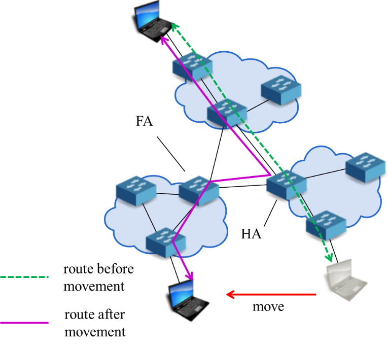
In this section, we introduce related works of IP mobility management and summarize their problems. Internet Engineering Task Force (IETF) standardized Mobile IPv4 to realize IP mobility management [4]. Mobile IPv4 is a protocol to maintain communication between a MN and a Correspondent Node (CN), which communicates with the MN, after the MN moves to other network domain. Figure 2 shows its overview. Mobile IPv4 uses a Home Address (HoA) and a Care-of Address (CoA) to continue communication after MN’s move. HoA is an address that MN was using in the source domain and CoA is an address MN is using in the destination domain. The MN registers its binding-cache to its Home Agent (HA). Binding-cache is a set of HoA and CoA of a MN. The HA transfers the packets sent to HoA, to CoA. However, there is a possibility that a MN communicate with a CN over a redundant route, which we call triangle routing problem, depending on the location of the HA.
Mobile IPv6 is also standardized by IETF [5]. In addition to functions of Mobile IPv4, Mobile IPv6 has a route optimization function which enables MNs to communicate with the most suitable route. However, this is an optional function so only the MNs with support for route optimization can use this function.
|
|
In order to realize IP mobility management, we need to share a variety of information such as HoA, CoA, lifetime of Binding Cache, etc. among a MN, a HA, and a Foreign Agent (FA). IETF standardized Mobile IPv6 Management Information Base [10]. It defines large amount of information needed for Mobile IPv6. It is essential to select where to share plentiful information efficiently to realize IP mobility management. In Mobile IPv4 and Mobile IPv6, the MN registers its binding cache to its HoA. Thus, there is no need of searching for where to share information.
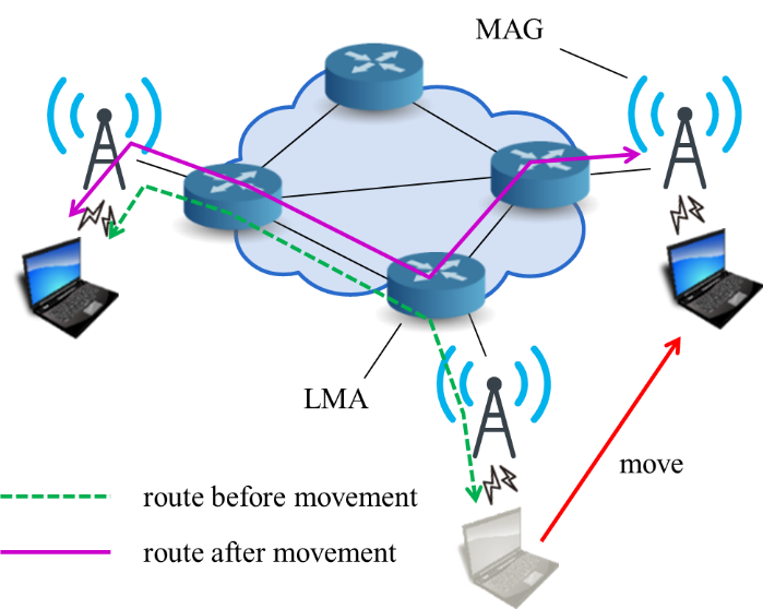
In Mobile IPv4 and Mobile IPv6, the MN needs to conduct IP mobility management. On the other hand, Proxy Mobile IPv6 (PMIPv6) executes IP mobility management on network equipment. Figure 3 shows its overview. The network equipment execute process for IP mobility management in PMIP. Therefore, there is no need of MN to involve in IP mobility management. Local Mobility Anchor keeps bindings of HoA and Proxy-CoA. Mobile Access Gateway (MAG) detects MNs and registers bindings to LMA. After a MN moves, MAG registers the MN’s HoA and Proxy-CoA binding to LMA. Packets sent to the MN’s HoA are transferred to the MN via LMA. Like Mobile IPv4 and Mobile IPv6, PMIP also has some possibility of triangular routing.
2.2. SDN based IP mobility management
SDN enables us to control networks intensively and flexibly. Therefore, SDN has attracted attentions as a means to solve the route optimization problem. Using SDN, network devices execute all the IP mobility management processes. Thus, unlike Mobile IPv4 and Mobile IPv6, the MN does not need to be equipped with IP mobility management functions. For this reason, there are some IP mobility management approaches using SDN. Papers [7] and [8] show route optimization mechanisms in the case when intra-domain handover occurs. However, in the case of inter-domain handover, the mechanism in [7] uses Mobile IP, therefore MNs need to be equipped with route optimization function to optimize route after handover. The mechanism in [8] regards inter-domain handover as infrequent and broadcasts this event to all other controllers. Therefore, amount of traffic increases when inter-domain handover occurs frequently in a network consisted by many domains.
2.3. Problems of related works
|
|
We summarized the problems of the related works in Table. We confirm that existing works cannot realize intra-domain route optimization, inter-domain route optimization, and efficient selection of domain to share information all together.
The papers [7] and [8] applied SDN to solve the problem of Mobile IP, route optimization, but SDN controllers can only control the network under their managed domain. This means that these approaches focus on intra-domain route. However, in recent network environment, users move freely to various domain networks while using IP services. Therefore, we have to consider the IP mobility management in multiple domain networks.
To realize IP mobility management in multiple domain networks, we need SDN controller in each domain to share information of MNs. However, if a SDN controller broadcasts the information to all other SDN controllers, it might cause large amount of traffic in a situation that inter-domain handover occurs frequently. Hence, we need a mechanism to share information efficiently in multiple domain networks.
3. SDN Based IP Mobility Management Scheme Considering Inter-Domain Handovers
3.1. Overview
In this section, we propose a SDN based IP mobility management scheme considering inter-domain handovers to solve the problems explained in section 2. We first show the
Table Summary of related works
| approaches | Mobile IPv4 [4] | Mobile IPv6 [5] | PMIPv6 [6] | Paper [7] | Paper [8] |
| Intra-domain routing | × | △ | △ | ○ | ○ |
| Inter-domain routing | × | △ | × | ○ | △ |
| Domain selection to share information | ○ | ○ | ○ | × | ○ |
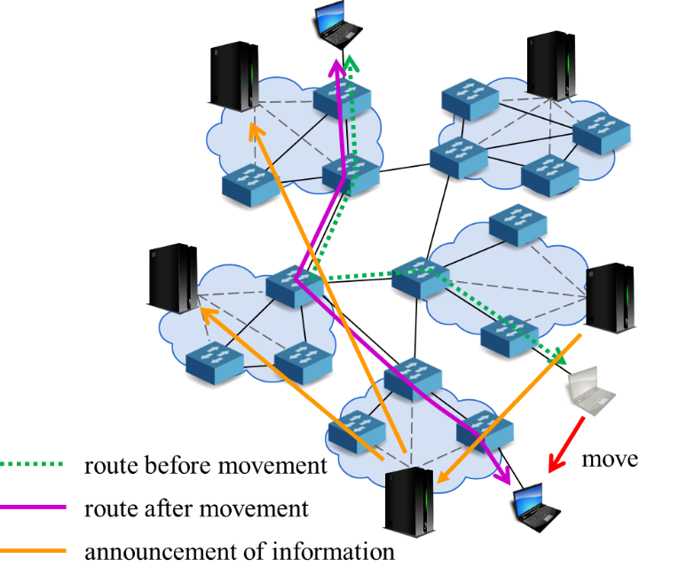
overview of our proposed scheme and discuss the details of composing functions later. We show the overview of our scheme in Figure 4. This approach realizes inter-domain route optimization while sharing information efficiently with two functions; Management Information Sharing Function and Inter-domain Routing Function.
The Management Information Sharing Function (MISF) searches for the domain which MN was in before movement (source domain) and modifies the domain to exchange MN information to reduce traffic load between SDN controllers. The Inter-domain Routing Function (IDRF) calculates end-to-end route between MN and CN in the domain MN moved into (destination domain) and announces this route only to the domains in the path to optimize inter-domain routes.
We assume that inter-domain topology changes do not occur frequently. Therefore, the SDN controllers have an inter-domain topology information. Inter-domain topology information consists of SDN controller’s IP address of each domain, network address of each domain, and inter-domain link information. The functions we mentioned above use this inter-domain topology information to search domain and calculate routes.
|
|
We show the components of our proposal in Figure 5. The components include SDN controllers, SDN switches, a MN, and a CN. Our scheme supports IPv4 network with two layers of network: a SDN controller network and a SDN switch network. SDN controller network is consisted of each domain’s SDN controller and is used for SDN controllers to exchange information to optimize MN-CN route. SDN switch network is consisted of SDN switches. We call the SDN switch network managed by one SDN controller “domain”.
3.2. Management Information Sharing Function
|
|
We describe the detailed design of MISF with an example. The network we use for explanation is shown in Figure 4. We assume that a MN moves to a destination domain from a source domain during a communication with a CN and the SDN controller of the destination domain detects the connection of the MN. The MN’s IP address changes after move. We show below the MAC address, IP address which the MN was using in the source domain (former IP address) and IP address which the MN is using currently in the destination domain (current IP address).
- MAC address: 00:00:00:00:00:11
- former IP address: 10.0.1.1
- current IP address: 10.0.2.1
We define the names of domains and SDN controllers that involve in MN handover as below:
- Domains
- Dd: the domain that MN belongs to after move
- Ds: the domain that MN belongs to before move
- Dc: the domain that CN belongs to
- SDN controllers
- Cd: SDN controller that manages Dd
- Cs: SDN controller that manages Ds
- Cc: SDN controller that manages Dc
|
|
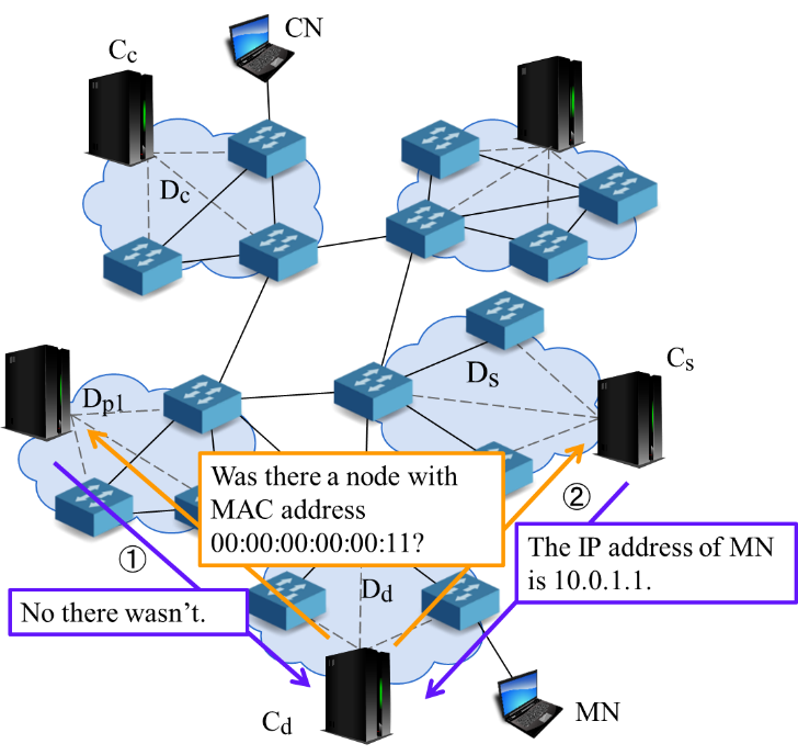
We describe the procedure of MISF step by step.
- Cd searches for Ds based on MAC address of MN.
Cd sends queries in order from neighboring domains like in Figure 6. SDN controllers of the domains that received the query search their domain to check if MN belonged to, and sends the result to Cd for a reply. When MN was not in their domain, they reply the absence of MN. When MN was in their domain, they reply the IP address MN was using.
- Cd generates node connection information from the IP address sent from Cs.
Node connection information consists of following information.
- MAC address of MN
- former IP address
- current IP address
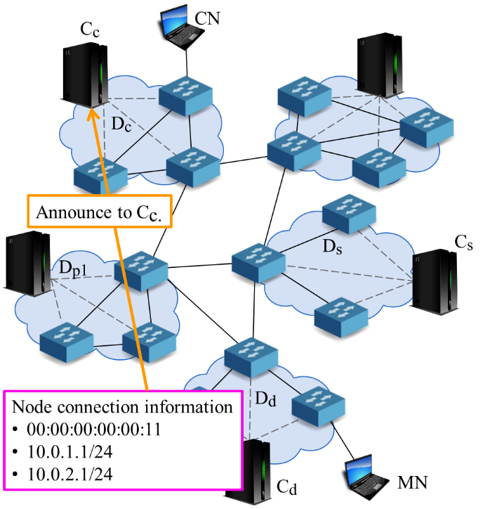
- Cd sends node connection information to Cc.
Cd sends the information as shown in Figure 7. On this occasion, Cd gets the IP address of CN from header of the packet sent from MN to CN and derive the information of Cc.
3.3. Inter-domain routing function
|
|
Next, we explain the detailed design of IDRF following the example we used in the explanation of MISF in section 3.2.
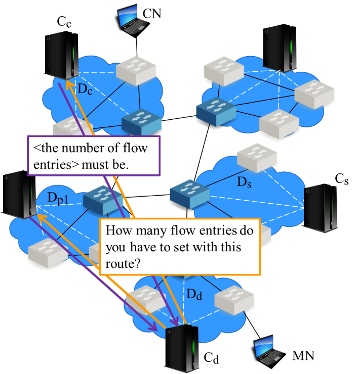
- Cd calculates the MN-CN inter-domain route.
We regard each domain as a node and calculate inter-domain route. We take the number of inter-domain hops (Nhop) and the total number of flow entries that are needed to be installed in SDN switches (Nflow) into account to select a route that is the shortest and able to suppress the resource consumption of SDN controllers.
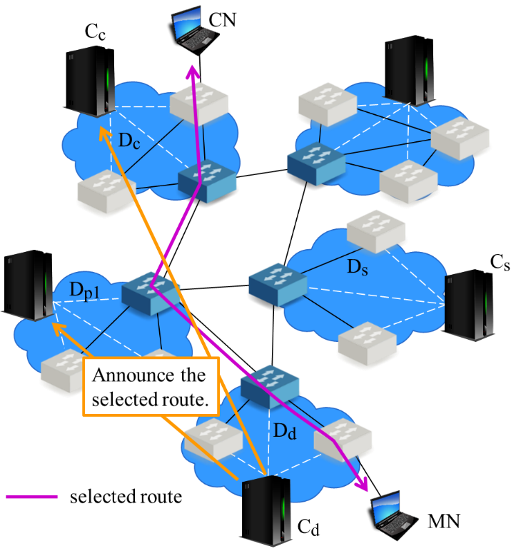
- Cd announces the route information to the SDN controllers of the domains to go via the selected route.
In the example, Cd announces the route to the domains shown in Figure 8.
- Each SDN controller generates flow entries based on the received route information and installs them to their corresponding SDN switches.
Especially, the SDN switch that the CN connects to check flow entries and rewrites the packets sent between the MN and the CN based on the node connection information. This keeps the IP address of the MN seen from the CN the same as before and it enables the communication to continue between the MN and the CN as before movement. Concretely, we set the flow entries as shown below.
- Rewrite the destination IP address of the packets sent from the CN to the MN from former IP address to current IP address.
- Rewrite the source IP address of the packets sent from the MN to the CN from current IP address to former IP address.
We would explain the detail of Step 1 mentioned above. Concretely, we choose the route with minimum Nflow in the routes with minimum Nhop in the following steps.
- Cd checks for routes with minimum Nhop based on inter-domain topology information.
We use breadth first search algorithm for this search.
- If there is only one route with minimum Nhop, we choose this route as the shortest route. If there are two or more routes with minimum Nhop, we then compare Nflow of each route.Cd asks SDN controllers of each domain via listed route the number of flow entries they need to install for each route like in Figure 9. The SDN controllers reply the number of flow entries to Cd and Cd calculates Nflow of each route.
|
|
- Cd chooses the route with minimum Nflow as the finally decided route.
4. Performance Evaluation
4.1. Overview
We carried out simulation experiments to validate an effectiveness of our proposed scheme. Especially, we confirmed the reduction on both communication load between SDN controllers by MISF and reduction effect on communication delay between a MN and a CN by IDRF.
We used OpenDaylight Lithium [11] as SDN controllers, Open vSwitch [12] as SDN switches, and OpenFlow1.3 [13] as the communication protocol between the SDN controllers and the SDN switches. We implemented the two functions we introduced in section 3 into SDN controllers.
We equipped two approaches for comparison with our proposed scheme.
- approach 1: announces move of MN to all domains
We replaced MISF to a function to announce the movement of MN to all the SDN controllers [8].
- approach 2: transfers packets sent to MN from source domain
We replaced IDRF to a function to set route via the domain where the MN belongs to before moving [4-7].
|
|
We constructed a virtual network as an experimental network with Mininet2.2.1 [14]. The bandwidth capacity of the links between SDN switches are set to 1Mbps and delay of each links is set to 10ms.
The experiments are conducted in the following scenario:
- A MN moves from Ds to Dd 5 seconds after the MN and a CN started communication.
- Cd searches for source domain and retrieve former IP address of the MN.
- Cd generates node connection information and announces it to Cc.
- Cd calculates new communication route between the MN and the CN.
- Cd announces the new route and SDN controllers of the domains involved in the new route install flow entries.
In this paper, we carried out three types of experiments.
- Experiment 1: evaluation of MISF
- Experiment 2: evaluation of IDRF
- Experiment 3: comprehensive evaluation of the proposed scheme
4.2. Experiment 1: Evaluation of MISF
In Experiment 1, we focused on traffic loads of communication between SDN controllers. We arranged three networks: each network consists 5, 10, and 15 domains, respectively. The number of inter-domain hops between source domain and destination
|
|
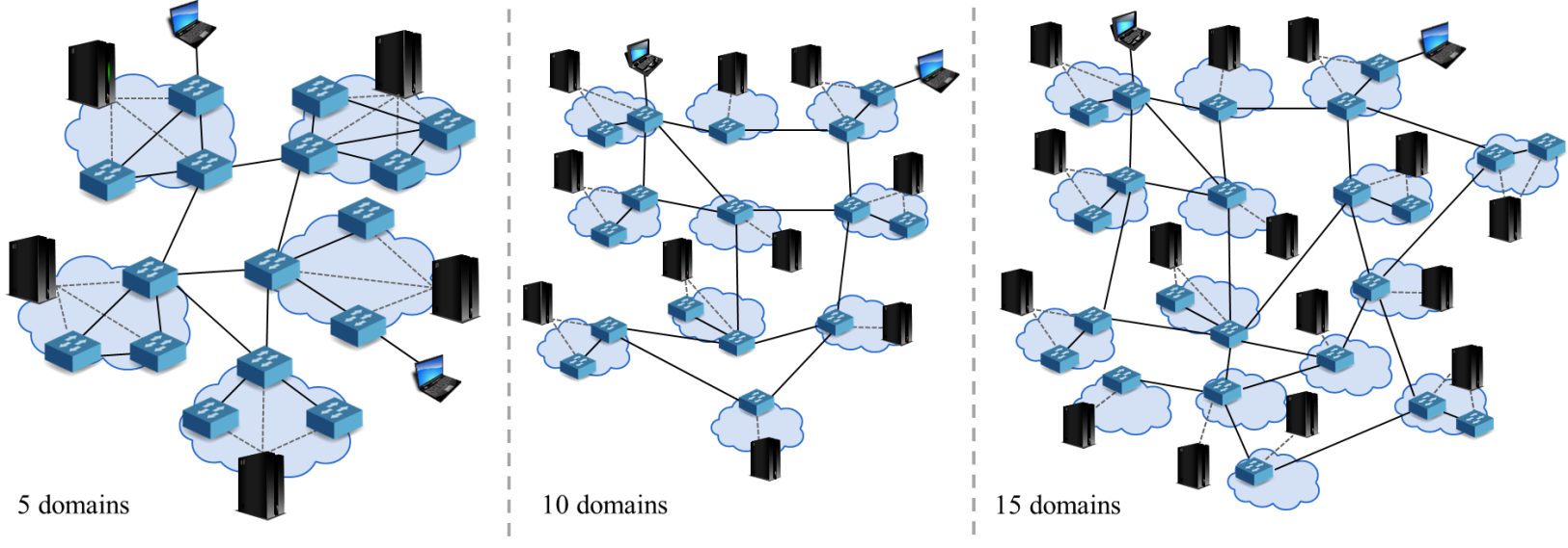
domain is 1. The domains increase concentrically like shown in Figure 10.
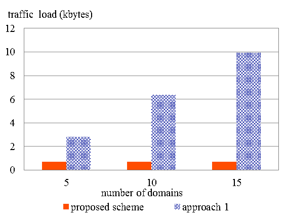
Figure 11 shows how the traffic load changed as the number of domains changed. In case of approach 1, traffic load increased according to the increase of number of domains. In contrast, traffic load in the case of proposed scheme did not raise even though the number of domains increased.
4.3. Experiment 2: Evaluation of IDRF
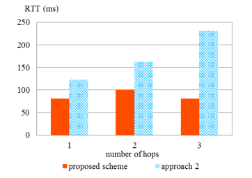
In Experiment 2, we focused on the delay of communication (Round Trip Time: RTT) between the MN and the CN after MN’s move. We arranged a network with 10 domains and set the number of inter-domain hops between Dd and Ds to 1, 2, and 3, respectively, as shown in Figure 12.
|
|
|
|
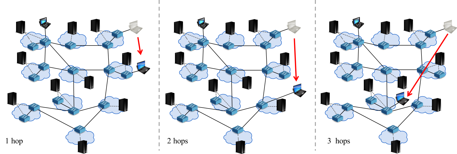
Figure 13 shows the result of Experiment 2. In the case of approach 2, RTT increased according to the increase of number of inter-domain hops between Dd and Ds. In contrast, the proposed approach succeeded to keep RTT less than that of approach 2 in any case.
4.4. Experiment 3: Comprehensive evaluation of the proposed scheme
In Experiment 3, we compared traffic load between SDN controllers and the RTT between the MN and the CN of the proposed scheme, approach 1, and approach 2. We set the parameters as below:
|
|
- The number of inter-domain hops between the MN and the CN: 1, 2, 3
- The number of domains consisting an experimental network: 8, 9, 10
Figure 14 shows the topology of network when the number of domains are 8, 9, and 10, respectively. The MN moves as indicated by the arrows in the figure.
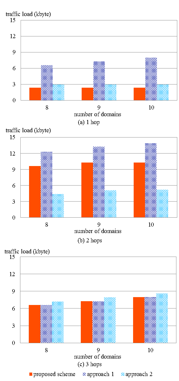
We show the traffic load between the SDN controllers for each number of hops between the MN and the CN in Figure 15. Traffic loads increase as Ds gets farther from Dd with the proposed scheme and the approach 2, whereas with the approach 1, traffic load was not affected by the number of hops but influenced by the number of domains.
|
|
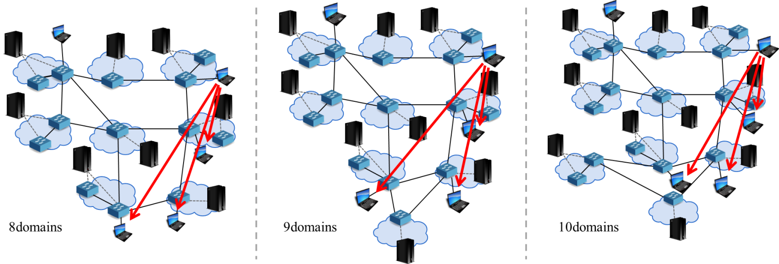
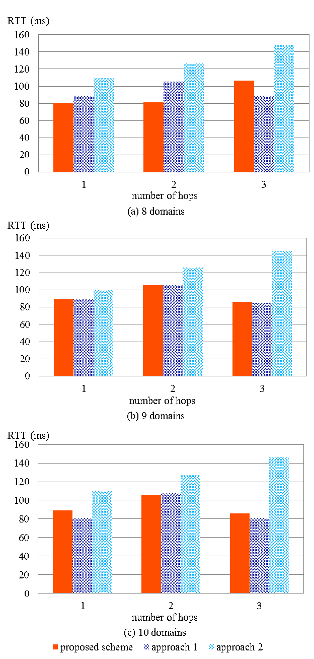
Figure 16 shows the RTT of the communication between the MN and the CN for each number of domains. With the proposed scheme and the approach 1, RTT differs by the number of hops but is always smaller than that of the approach 2 in any case. With the approach 2, RTT increased as the number of hops between Ds and Dd got bigger. However, the results of the proposed scheme and the approach 1 showed no relevance to the number of hops between Ds and Dd.
4.5. Summary of evaluations
We discuss the results of Experiment 1. In case of the proposed scheme, the closer the source domain was to destination domain, the smaller the traffic load was because our scheme queries from neighbors.
However, the traffic load of the approach 1 increased as the number of domains increased. This is because the approach 1 announces to all the domains in the network regardless of the position of the source domain.
Next, we discuss the results of Experiment 2. In case of the proposed scheme, the number of inter-domain hops does not become larger than the number that can be taken by the approach 2. Therefore, the communication delay in proposed scheme gets smaller than approach 2. This is due to the fact that the longest route the proposed scheme chooses is the same route as the one chosen by approach 2.
Finally, we analyze the results of Experiment 3 according to the following viewpoints: traffic load between SDN controllers and RTT of communication between the MN and the CN after MN’s movement.
First we talk about traffic load between SDN controllers. The proposed scheme and approach 1 exceeded approach 2 in traffic load between the SDN controllers. However, as the number of inter-domain hops between source domain and destination domain got bigger, traffic load of the proposed scheme and approach 2 tended to get bigger. For examples, we understand that when Ds and Dd were 3 hops away, traffic load of proposed scheme was pretty similar to that of approach 1 as we can see from Figure 15 (c). As Ds was 3 hops away from Dd, Cd ended up searching all the domains. When Ds and Dd was 2 hops away, traffic load of approach 2 was the biggest of all approaches. Approach 2 used MISF, the same function as the one proposed scheme uses. Thus, the traffic load of this function was the same as that of the proposed scheme. The difference came from the traffic load of IDRF. The difference in the communication route
|
|
|
|
set after MN’s movement caused the difference in amount of communication made between SDN controllers and this affected the overall traffic load. Figure 15 (b) shows that when Ds and Dd were 2 hops away, the traffic load of the proposed scheme and approach 1 exceeded the traffic load of approach 2 greatly. In this case, there were several routes with minimum inter-domain hops. Therefore, IDRF queried for the number of flow entries that was needed to be installed for each route. This querying caused the increase of the traffic load. This fact shows that by asking the number of needed flow entries, the traffic load between the SDN controllers increases.
Next, RTT of communication between the MN and the CN after MN’s movement. With approach 2, RTT increased as the number of hops between Ds and Dd increased. In approach 2, packets sent to the MN were first sent to Ds and then got transferred to the MN. Thus, the communication route gets longer as the MN moves farther. In contrast, the proposed scheme and approach 1 selected the shortest route regardless of the position of Ds. Therefore, RTT did not get too big. Besides, the transferring route was the longest route that could be chosen in the proposed scheme and approach 2. Thus, these approaches could keep RTT the same as that of approach 2 or smaller.
From the results mentioned above, the approach 1 and the approach 2 can only hold back the RTT of communication between the MN and the CN after MN’s move, or traffic load between SDN controllers. However, the proposed scheme is able to deal with both.
4.6. Discussion
These quantitative experimental results mentioned above reveal the contribution of our proposed scheme in practical use. This achievement enables the suppression of the consumption of limited network resources while enabling users of MNs to move around keeping seamless and fast communication even if they moved across domains. For example, consider the situation where many users work with laptop PC or tablet PC to download data from cloud servers or to upload data. The users can smoothly download/upload large data from/to cloud servers while they are moving, like during transit time. Concerning interactive-type applications such as remote login terminal or VDI environment, the users can use the services continuously when the connecting network domain changes.
Generally speaking, to avoid the termination of services or processes when MNs move across network domains, application-level handover function is usually implemented in the applications. When IP address of a MN changes according to the MN’s movement, the handover function terminates the transport connection on the previous IP address, and then establishes a new transport connection on the new IP address. By this function, the data communication sessions seem to continue transparently and application logic can handle the sessions seamlessly. However, not all the applications have this feature implemented. This is because the mechanism is relatively complicated and it is necessary to deal with the server side as well. Our approach enables this functionality in network level. It means that all the Internet applications can utilize their network-dependent functions seamlessly in case that MNs move across the network domain.
Furthermore, when a user is at a place that the service areas of different access points overlap, the MN shifts its connecting access point back and forth depending on the link condition even when the user is not moving physically. Proposed scheme can manage this kind of handover and keep communication quality. Meanwhile, a standardization activity of a fast initial setup of Wi-Fi link is progressing as IEEE802.11ai [15]. This function would enable a Wi-Fi client to establish a secure link setup within 100ms. If this standard will widely be used in the above environment, switching of access point may occur very rapidly frequently in near future. There are no technologies currently available to deal with such situations, and we can expect that our proposed scheme will work effectively in such situations.
5. Conclusion
This paper aimed at realizing seamless connection and route optimization in SDN based IP mobility management on inter-domain handovers. It is difficult to realize efficient information exchange between SDN controllers and route optimization together. To solve this problem, we proposed the SDN based IP mobility management scheme considering inter-domain handovers. As simulation results show, we achieved to optimize route while keeping management information exchange traffic between SDN controllers low.
As the future works, we need to improve IDRF. By extending the algorithm to handle weight of paths, we can take more kinds of information into account, such as bandwidth of inter-domain links and network usage.
- M. Hata, S. Izumi, T. Abe, and T. Suganuma, “A proposal of SDN based mobility management in multiple domain networks,” in 18th Asia-Pacific Network Oper. Manage. Symp., 1–4, 2016. https://doi.org/10.1109/APNOMS.2016.7737263
- D. Giusto, A. Iera, G. Morabito, and L. Atzori, Eds., The Internet of Things. Springer-Verlag GmbH, 2010. https://doi.org/10.1007/978-1-4419-1674-7
- J. Gubbi, R. Buyya, S. Marusic, and M. Palaniswami, “Internet of things (IoT): A vision, architectural elements, and future directions,” Future Gener. Comput. Syst., Vol. 29, No. 6, 1645–1660, 2013. https://doi.org/10.1016/j.future.2013.01.010
- C. E. Perkins, “RFC 5944 – IP mobility support for IPv4, revised,” https://tools.ietf.org/html/rfc5944, 2010.
- C. E. Perkins, D. B. Johnson, and J. Arkko, “RFC 6275 – Mobility support for IPv6,” https://tools.ietf.org/html/rfc6275, 2011.
- S. Gundavelli, K. Leung, V. Devarapalli, K. Chowdhury, and B. Patil, “RFC 5213 – Proxy mobile IPv6,” https://tools.ietf.org/html/rfc5213, 2008.
- Y. Wang and J. Bi, “A solution for IP mobility support in software defined networks,” in 23rd Int. Conf. Comput. Commun. Networks, 1–8, 2014. https://doi.org/10.1109/ICCCN.2014.6911783
- Y.Wang, J. Bi, and K. Zhang, “Design and implementation of a software-defined mobility architecture for IP networks,” Mob. Network Appl., Vol. 20, No. 1, 40–52, 2015. https://doi.org/10.1007/s11036-015-0579-2
- “Software-Defined Networking (SDN) definition,” Open Networking Foundation, https://www.opennetworking.org/sdn-resources/sdndefinition, (Accessed 2017).
- G. M. Keeni, K. Nagami, K. Koide, and S. Gundavelli, “RFC 4295 – Mobile IPv6 management information base,” https://tools.ietf.org/html/rfc4295, 2006.
- “The OpenDaylight platform,” Linux Foundation, https://www.opendaylight.org/, (Accessed 2017).
- “Open vSwitch,” Linux Foundation, http://openvswitch.org/, (Accessed 2017).
- N. McKeown, T. Anderson, H. Balakrishnan, G. Parulkar, L. Peterson, J. Rexford, S. Shenker, and J. Turner, “OpenFlow: enabling innovation in campus networks,” ACM SIGCOMM Comput. Commun. Rev., Vol. 38, No. 2, 69–74, 2008. https://doi.org/10.1145/1355734.1355746
- “Mininet: An instant virtual network on your laptop (or other pc) – mininet,” Mininet Team, http://mininet.org/, (Accessed 2017).
- “IEEE P802.11 – TASK GROUP AI – MEETING UPDATE,” http://www.ieee802.org/11/Reports/tgai_update.htm, (Accessed 2017).