Spatial Modulation Technique For Filtered-OFDM Based Wireless Transmission

Adv. Sci. Technol. Eng. Syst. J. 2(3), 981–986 (2017);
 DOI: 10.25046/aj0203124
In this paper, a spatial modulation (SM) which provides no synchronization between the transmitting antennas and avoids inter-channel interference (ICI) at the receiver input while maintaining high spectral efficiency is applied to filtered-orthogonal frequency division multiplexing (F-OFDM) transmission. The SM technique maps a block of information bits into two information carrying units, namely, a symbol chosen from a signal constellation diagram and a unique antenna number selected from the set of transmit antennas. Therefore, for F-OFDM wireless transmission, each subcarrier within the subband is mapped to one of the transmitting antennas. During wireless data transmission, there is only one active antenna transmitting power on that subcarrier at an instant of time and the rest of the antennas remains silent (zero power). At the receiver, a maximum-likelihood (ML) detector recovers the transmitted block of information bits by estimating the transmitted signal and the respective transmit antenna number. The effectiveness of the proposed method is verified using numerical results.
1. Introduction
The unprecedented increase of mobile communications, wireless Internet access and multi-media applications has been driven by telecommunications companies and re-searchers to conceive new transmission technologies, proto-cols, and network infrastructure solutions in order to max-imize both throughput and spectral efficiency [1]. For the next generation of wireless communication, it has become necessary to provide higher data rate and improve spectral efficiency. Employing multi–antennas at transmitter and re-ceiver has shown to be an effective technique to achieve spectral efficiency over the past few years. The use of spatial multiplexing using multiple input multiple output (MIMO) was first proposed in [2]. MIMO technology is one of the techniques employed to attain high spectral effi-ciency by transmitting multiple data streams from multiple antennas [3]. However, the MIMO transmission is depen-dent on transmit and receive antenna spacing [4, 5], syn-chronization of the transmit antenna [6], as well as the al-gorithm needed for inter-channel interference (ICI) reduc-tion at the receiver input. The Bell Labs Layered Space-Time Architecture (BLAST) in [7] proposed MIMO detection algorithms, named vertical BLAST (V-BLAST) [8]. In V-BLAST, multiple data streams are transmitted separately and detected successively by employing both an array pro-cessing (nulling) and interference cancelation techniques.
OFDM is another promising technique proposed for transmitting high speed data over wireless channels in fu-ture mobile communication systems [9]. OFDM has been useful in several wireless standards, for example, digital audio and video broadcasting (DAB) and (DVB-T), IEEE 802.11a [10], the IEEE 802.16a metropolitan area network (MAN), and the local area standard (LAN) [11]. Although, OFDM features seems attractive, there is still technical challenges that needs to be addressed for future wireless transmission [12, 13].
Recently, a new extension to OFDM has been proposed, namely, F-OFDM in [12, 13]. The most significant differ-ence of F-OFDM, as opposed to the conventional OFDM, is that the former total bandwidth has been divided into mul-tiple subband. In addition, each subband have a distinct subcarrier spacing with its own cyclic prefix (CP) and filter. On the other, in conventional OFDM, total bandwidth con-sists of a single block and has the same subcarrier spacing between the individual subcarriers. Note that, there is de-The proposed architecture of SM F-OFDM system is depicted in
Figure 1, with the F-OFDM transmitter showing in Figure 2, while F-OFDM receiver is illustrated in Figure 3. Suppose the input Q(k) is m n matrix which represents the transmitted symbols, where m is the total number of bits per symbol per subcarrier and n denotes the total number of
| gree of flexibility in F-OFDM than its counterpart OFDM. | subcarriers of the multiple subband of F-OFDM system. By | ||||
| The details can be found in [12, 13]. | using the SM mapping rule as listed in Table I, this matrix | ||||
| Therefore, in this paper, SM is applied to F-OFDM, | is mapped into X(k) of size Nt n. | ||||
| namely, spatial modulation F-OFDM (SM F-OFDM), | From Table I, the SM mapping rule, maps each col- | ||||
| which provides higher spectral efficiency as a result of both | umn in Q(k) into 4QAM and BPSK signal constellations | ||||
| SM and F-OFDM advantages. The main contributions of | respectively. In addition, one transmit antenna from a set of | ||||
| this work can be summarized as follows: (i) Analogue to | two (QPSK) and four (BPSK) antennas is assumed. Herein, | ||||
| [9], SM F-OFDM is designed for wireless transmission. (ii) | 4QAM and BPSK modulation schemes were adopted in this | ||||
| Binary phase shift keying (BPSK) and quadrature ampli- | work. As can be seen in Table I, the encoding mechanism | ||||
| tude modulation (QAM) modulation schemes were adopted | are Nt = 2 and M = 4 when QAM is adopted. Note that, | ||||
| for SM mapping rule. | three information bits can be mapped onto 4-QAM with | ||||
| The remaining sections are organized as follows: | In | two transmit antennas selected. Similarly, for BPSK, the | |||
| Section II, the system model of SM-F-OFDM is presented. | same spectral efficiency can be achieved with Nt = 4 and | ||||
| Simulation results are provided in Section III and conclud- | M = 4. Thus the F-OFDM system can convey three bits | ||||
| ing summaries are drawn in Section IV. | in each time slots. The number of information bits that can | ||||
| Throughout the paper, the following notations are used. | be transmitted on each F-OFDM subcarriers is given in (1). | ||||
| Bold lowercase and bold uppercase letters denote vectors | According to the SM mapping rule, the matrix Q(k) has | ||||
| and matrices, respectively. We use [:]T and k:kF to de- | one nonzero element in each column at the position of the | ||||
| note transpose and Frobenius norm of a matrix or a vector, | mapped transmit antenna number. All the other elements | ||||
| respectively. iˆ(k) is the estimated transmit antenna index | in that column are defined as zero. It is worth mentioning | ||||
| (number) and xˆiˆ(k) is the estimated transmitted symbol. F- | that, when Nt = 1 simplifies SM F-OFDM to conventional | ||||
| OFDM modulator-1 contains data belong to first antenna | single antenna communications. | ||||
| and so forth and denotes time convolution. | Supposing in Figure 1, | an input bit | sequence of | ||
| [0 0 1]T (column vector in Q(k)) from Table I, is mapped | |||||
| 2 System Model of SM F-OFDM | to the QAM symbol – 1 + j and the first transmit antenna | ||||
| by using SM mapping. Thus only the first antenna trans- | |||||
| In this section, SM is discussed briefly. Suppose the total | mits this symbol on the first F-OFDM subcarrier, whereas | ||||
| other antenna remains silent (zero power). As a result, the | |||||
| number of transmit and receive antennas is denoted by Nt | first column vector in X(k) is [ | 1 + j 0]T . The second bit | |||
| and Nr respectively, M being the cardinality of the signal | sequence is [1 1 0]T and is mapped to [0 | 1 j]T , and | |||
| constellation. Hence, the rate of SM (bits per channel use | so on. Similarly, the same approach is adopted for BPSK | ||||
| – (bpcu)) for arbitrary Nt and M respectively, can be given | symbols. The resultant symbols in each row vector xv (k) | ||||
| by [14],[15] | |||||
| are the data that will be transmitted on all subcarriers from | |||||
| RSM = log2(Nt) + log2(M) | (1) | transmit antenna v. And F-OFDM modulator will be used | |||
| to modulate each row vector xv (k). | |||||
| where log2(Nt) defines the single active transmit antenna | At the F-OFDM modulator output, sv (t) vector is gener- | ||||
| and log2(M) is the transmitted QAM/BPSK modulation | ated. Each sv (t) vector generated has a unique and disjoint | ||||
| symbols. Note that the Nt, Nr and M, respectively, can | set of F-OFDM subcarriers. The resulting output vectors at | ||||
| be chosen independently [16]. The basic principle of SM is | the F-OFDM modulator will be transmitted simultaneously | ||||
| that, it maps multiple information bits into one information | from the Nt over the channel H(t). At the receiver, the re- | ||||
| symbol with respect to their corresponding transmit antenna | ceived matrix Y(t) can be expressed as | ||||
| number. The number of information bits that can be trans- | Y(t) = H(t) | S(t) + G(t) | (2) | ||
| mitted in SM technique depends on the signal constellation | |||||
| diagram employed as well as the given number of transmit | where S(t) is a matrix that has all F-OFDM symbols that | ||||
| antennas. It is important to note that the SM utilizes the dis- | are transmitted from all transmit antennas. G(t) is the ad- | ||||
| tinctiveness and random nature of the wireless channel for | ditive noise matrix, in which each element is assumed to be | ||||
| communication. The following summarized SM character- | an independent and identically distributed (iid) zero mean | ||||
| istics [14]: | complex Gaussian random variable with variance N2 . H(t) | ||||
| 1) At any signaling time instance, only one transmit an- | is the Nr Nt channel matrix between transmit antennas v | ||||
| tenna is active for data transmission while the other | and receive antennas k, respectively and can be expressed | ||||
| antennas remains silent. | as (3) | ||||
| 0 | ||||
| B h1;1 (t) | ||||
| H (t) = | B | h2;1::: (t) | ||
| B | ||||
| B | ||||
| B | ||||
| B | ||||
| B | h | Nr ;1 | (t) | |
| B | ||||
| B | ||||
| B | ||||
B
B
B
B
B
@
h1;2 (t)
h2;2 (t)
where hk;v is a complex fading coefficient between the vth transmit antenna and kth the receive antenna. hk;v is as-
| F-OFDM | |||
| Modulator -1 | |||
| q(k) | Spatial | F-OFDM | |
| Modulation | |||
| Modulator -2 | |||
| X(k) | |||
| F-OFDM | |||
| Modulator -M |
| H(t) | F-OFDM | |||||||||
| s | (t) | |||||||||
| 1 | Demodulator-1 | |||||||||
| ˆ | ||||||||||
| i(k ) | ||||||||||
| s | (t) | F-OFDM | ML | Spatial | ||||||
| 2 | Demodulator-2 | Detection | Demodulation | |||||||
| xˆ | (k) | |||||||||
| ˆ | ||||||||||
| Y(k) | i | |||||||||
| H(t) | ||||||||||
| N | r | |||||||||
| F-OFDM | ||||||||||
| Y(t) | ||||||||||
| s | (t) | Demodulator-M | ||||||||
| N | ||||||||||
| t | ||||||||||
q(k)ˆ
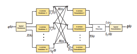 Figure 1: Proposed architecture of Spatial Modulation F-OFDM System for wireless transmission.
2. IFFT
SUBBAND-1
SUBBAND-Z
| PAR | ADD CP | FILTER |
| 1 | ||
| SER |
| M | M | M | S | I | (T) |
| PAR | ADD CP | FILTER | |||
| SER | Z |
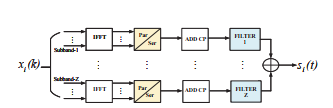 Figure 2: Block diagram of F-OFDM Transmitter.
| FILTER | REMOVE |
- CP
| Y(T) | M | M |
| FILTER | REMOVE | |
| Z | CP | |
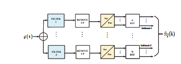 Figure 3: Block diagram of F-OFDM Receiver.
Table 1: Adopted SM F-OFDM Mapping Rule (3 bpcu).
| QAM | BPSK | |||||
| Input bits | Antenna Number | Transmit Symbol | Antenna Number | Transmit Symbol | ||
| 000 | 1 | +1+j | 1 | -1 | ||
| 001 | 1 | -1+j | 1 | +1 | ||
| 010 | 1 | -1-j | 2 | -1 | ||
| 011 | 1 | +1-j | 2 | +1 | ||
| 100 | 2 | +1+j | 3 | -1 | ||
| 101 | 2 | -1+j | 3 | +1 | ||
| 110 | 2 | -1-j | 4 | -1 | ||
| 111 | 2 | +1-j | 4 | +1 | ||
Four bits transmission using spatial modulation
| 10-1 | |||||||
| 10-2 | |||||||
| Error Rate | 10-3 | ||||||
| 10-4 | |||||||
| Bit | |||||||
| 10-5 | |||||||
| SM-4bits 2×4 8QAM -ZF | |||||||
| 10-6 | SM-4bits 4×4 | 4QAM -ML | |||||
| SM-4bits 2×4 | 8QAM -ML | ||||||
| SM-4bits 4×4 | 4QAM -ZF | ||||||
| 10-7 | 5 | 10 | 15 | 20 | 25 | 30 | |
| 0 | |||||||
SNR (dB)
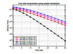 Figure 4: Illustration of BER performance for 4 bits per subcarrier employing ML and ZF detectors.
Three bits transmission using spatial modulation
| SM-3bits 2×4 4QAM -ML | |||||||
| 10-1 | SM-3bits 4×4 | BPSK -ML | |||||
| SM-3bits 4×4 | BPSK -ZF | ||||||
| SM-3bits 2×4 | 4QAM -ZL | ||||||
| 10-2 | |||||||
| Error Rate | 10-3 | ||||||
| 10-4 | |||||||
| Bit | |||||||
| 10-5 | |||||||
| 10-6 | |||||||
| 10-7 | 5 | 10 | 15 | 20 | 25 | 30 | |
| 0 | |||||||
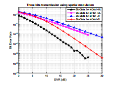 Figure 5: Illustration of BER performance for 3 bits per subcarrier employing ML and ZF detectors.
sumed to be iid complex zero mean Gaussian with variance one.
The receiver uses maximum likelihood detector to esti-mate the index, iˆ(k) and the transmitted symbol, xˆiˆ(k) can be expressed as
where x denotes the transmitted symbol vector, HT (t) is the transpose of the channel matrix in (3) and denotes the convolution.
| ˆ@ | xˆ@ | = arg max Pr Y | H ( | ) | xˆ | iˆ | 3 Simulation Results and Discussions | ||||||||||||||||
| hi ; | i | i;x | @ | t | ; | (4) | In this section, simulation results for the proposed SM F- | ||||||||||||||||
| = arg min | 2 | OFDM transmission is shown. Monte Carlo simulations is | |||||||||||||||||||||
| Y@ H (t) ;xˆˆ | F | ||||||||||||||||||||||
| i;x | i | used to evaluate bit error rate (BER) performance utilizing | |||||||||||||||||||||
| maximum likelihood (ML) detector at the receiver. In ad- | |||||||||||||||||||||||
| where Y@ is the output matrix from the ML for the sub- | dition, zero forcing (ZF) detector was employed for com- | ||||||||||||||||||||||
| carrier @, i.e. (@ : 1;2; :::; n) and | |||||||||||||||||||||||
| parison. Herein, it was considered that the receiver have | |||||||||||||||||||||||
| 2 | 3 | full channel knowledge and the receive antennas are sepa- | |||||||||||||||||||||
| 1 | Y@ H (t) ;xˆˆ | 2 | rated wide enough to avoid correlation. Flat Rayleigh fad- | ||||||||||||||||||||
| F | |||||||||||||||||||||||
| Pr Y@ H (t) ;xˆiˆ | = | exp | i | ing channel was also assumed. | |||||||||||||||||||
| Nr | 2Nr | 2 | |||||||||||||||||||||
| N | 6 | N | 7 | ||||||||||||||||||||
| 6 | 7 | ||||||||||||||||||||||
| 6 | 7(5) | ||||||||||||||||||||||
| 6 | 7 | ||||||||||||||||||||||
| 6 | 7 | ||||||||||||||||||||||
| 6 | 7 | ||||||||||||||||||||||
| is the conditional probability density | 4function (PDF) of | 5Y@ | 3.1 Three Bits Transmission | ||||||||||||||||||||
| given H(t) and xiˆ. Equation (4) estimates both the transmit | By using different configurations, a three bits per subcarrier | ||||||||||||||||||||||
| antenna number and the transmitted symbols jointly. The | |||||||||||||||||||||||
| SM demodulator, then used these two estimates to extract | transmission can be achieved. For SM, a 4 4 BPSK and | ||||||||||||||||||||||
| the transmitted information bits on this subcarrier by taking | 2 4 4QAM configuration convey three bits per subcarrier. | ||||||||||||||||||||||
| an inverse mapping process adopted by the same mapping | In Figure 4, SM 4 4 BPSK shows performance degrada- | ||||||||||||||||||||||
| table used at the transmitter. | tion as compared to SM 2 4 4QAM when ML detector | ||||||||||||||||||||||
| Similarly, the zero forcing (ZF) detector can be written | is used. A similar trend can be observed for ZF detector | ||||||||||||||||||||||
| as | as the same degradation performance is seen with the same | ||||||||||||||||||||||
| _@ | _@ | = HT (t) H (t) | 1 | x | configurations. The results in Figure 4 shows that the ML | |
| i | ; x | H (t) | (6) | detector estimation outperforms ZL detector estimation. |
Six bits transmission using spatial modulation
| SM-6bits 4×4 | 16QAM -ML | |||||||
| 10-1 | SM-6bits 4×4 | 16QAM -ZL | ||||||
| SM-6bits 2×4 | 32QAM -ZF | |||||||
| SM-6bits 2×4 | 32QAM -ML | |||||||
| 10-2 | ||||||||
| Error Rate | 10-3 | |||||||
| 10-4 | ||||||||
| Bit | ||||||||
| 10-5 | ||||||||
| 10-6 | ||||||||
| 10-7 | 5 | 10 | 15 | 20 | 25 | 30 | ||
| 0 | ||||||||
SNR (dB)
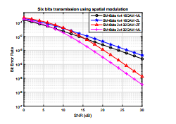 Figure 6: Illustration of BER performance for 6 bits per subcarrier employing ML and ZF detectors.
| 100 | ||||||
| 3 bits (2×4 4 QAM − ML) | ||||||
| 4 bits (2×4 8 QAM − ML) | ||||||
| −1 | 6 bits (2×4 32 QAM − ML) | |||||
| 10 | ||||||
| 10−2 | ||||||
| 10−3 | ||||||
| BER | ||||||
| 10−4 | ||||||
| 10−5 | ||||||
| 10−6 | ||||||
| 10−7 | 5 | 10 | 15 | 20 | 25 | 30 |
| 0 | ||||||
| SNR(dB) | ||||||
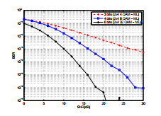 Figure 7: BER comparison performance for SM bits transmission, namely, 3, 4 and 6 bits, respectively when ML is adopted.
3.2 Four Bits Transmission
Four bits transmission can be achieved by the employment of SM 4 4 4QAM or 2 4 8QAM configuration. The com-parison BER results in Figure 5 shows that the ZF demon-strates the worst performance as compared to ML detector.
3.3 Six Bits Transmission
Figure 6 results extended the simulation to a spectral efficiency of 6 bits transmissions ML detection outperforms ZF detection.
It can be observed that the likelihood of errors for an-tenna detection increases with an increase in the number of transmit antennas. Therefore, the 2 4 SM system outper-forms 4 4 system at high SNR. An interesting feature of SM can be noticed in Figure 6, where the 2 4 32QAM for ZF detector BER curve crosses the 4 4 16QAM ML detec-tor at around 16 dB. This effect is a result of two estimation processes which is performed in SM, thus antenna number and transmitted symbol. Note that, the error level is dom-inated by the estimation of the transmitted symbol for low SNR, while the error level is dominated by the estimation of the transmit antenna number for a relatively high SNR. Hence, the scenario shown in Figure 6, for SN R < 16dB, lower constellation size and higher number of transmit an-tenna array is better for improved performance. On the other hand, for SN R > 16dB, higher constellation size and lower number of transmit antenna array is better. So there is a flexible tradeoff in this regard.
Figure 7 illustrates the BER comparison for distinct SM bits transmission, namely, 3 bits, 4 bits and 6 bits, respec-tively, for QAM modulation scheme.
It can be observed that the 6 bits SM transmission performs better than the 3 bits and 4 bits. Thus 6bits > 4bits > 3bits. This is because higher data rate can be achieved in the SM 6 bits transmis-sion leading to a higher spectral efficiency.
3. Conclusion
In this paper, spectral efficient multiple antenna transmis-sion technique, namely, spatial modulation (SM) is applied to F-OFDM for wireless transmission. The antenna pat-tern is considered as a spatial constellation in an innovative fashion by using SM technique to increase the spectral effi-ciency. By computer simulation, BER performance for the proposed scheme was evaluated for uncorrelated Rayleigh fading channel and compared with ZF detector. The pro-posed SM F-OFDM achieves a constant spectral efficiency in bits per subcarrier. Another significant merit of employ-ing SM is the possibility of interchanging the constellation size and number of transmit antenna array to achieve better performance with respect to the operating SNR. In a follows up work, this feature will be further exploited. Furthermore, the performance improvement of the system increases as the transmission rate increases, which makes it a potential candidate for high data rate transmission systems. In addition, due to the estimation processes in SM approach, it is worth investigating further new algorithms for detection to improve the performance.
- Marco D. R, Harald H., Ali G., Shinya S., and Lajos H., “Spatial Modulation for Generalized MIMO: Challenges, Opportunities, and Implementation ”. Proceedings of IEEE, pp. 1–47, 2013.
- Mehdi Maleki Pirbazari, “Space Modulation: Signal design and performance evaluation” . PhD dissertation – University of Akron, 2015.
- E. Telatar, “Capacity of Multi-Antenna Gaussian Channels”. European Transaction Telecommunication, vol. 10, no. 6, Novem-ber/December pp. 558-595, 1999.
- G. J. Foschini, M. J. Gans, and J. M. Kahn, “Fading Correlation and its Effect on the Capacity of Multielement Antenna Systems”. IEEE Transactions on Communications, vol. 48, March, pp. 502-513, 2000.
- S. Loyka and G. Tsoulos,, “Estimating MIMO System Performance Using the Correlation Matrix Approach” . IEEE Communications Letters, vol. 6, no. 1, pp. 19-21, January 2002.
- Marco. Chiani, Moe Z. W., and A. Zanella, “On the Capacity of Spatially Correlated MIMO Rayleigh-Fading Channels”. IEEE Transactions on Information Theory, vol. 49, no. 10, pp. 2363-2371, October 2003.
- G. J. Foschini, “Layered SpaceTtime Architecture for Wireless Communication in a Fading Environment when Using Multi-Element Antennas”. Bell Labs Technical Journal, vol. 1, no. 2, pp. 41-59, September 1996.
- P. W. Wolniansky, G. J. Foschini, G. D. Golden, and R. A. Valenzuela, “V-BLAST: An Architecture for Realizing Very High Data Rates Over the Rich-Scattering Wireless Channel”. Proceedings of the IEEE International Symposium on Signals, Systems, and Elec-tronics (ISSSE), pp. 295-300, September/October 1998.
- R. Mesleh, H. Haas, C.W. Ahn and S. Yun, “Spatial Modulation OFDM”. In the Proceedings of the 11th International OFDM-Workshop 2006 (InOWO’06), pp. 288–292, August 30-31, 2006.
- IEEE, Part 11, “Wireless LAN Medium Access Control (MAC) and Physical Layer (PHY) Specifications: High Speed Physical Layer in the 5 GHz Band”. IEEE Standard 802.11a, 1999.
- IEEE, Part 16, “Local and Metropolitan Area Networks: Air Inter-face for Fixed Broadband Wireless Access Systems”. IEEE Standard 802.16a, 2003.
- Xi Zhang, Ming Jia, Lei Chen, Jianglei Ma, Jing Qiu, “Filtered-OFDM Enabler for Flexible Waveform in The 5th Generation Cellular Networks”. Accepted to IEEE GLOBECOM, San Diego, CA, pp. 16–20, Dec. 2015.
- Javad Abdoli, Ming Jia, and Jianglei Ma, “Filtered OFDM: A New Waveform for Future Wireless Systems ”. IEEE 16th International Workshop on Signal Processing Advances in Wireless Communications (SPAWC), pp. 60–70, 2015.
- M. Di Renzo, H. Haas, and P. M. Grant, “Spatial modulation for multiple-antenna wireless systems: A survey”. IEEE Communications Magazine, vol. 49, no. 12, pp. 182-191, Dec. 2011.
- R. Y. Mesleh, H. Haas, S. Sinanovic, C. W. Ahn, and S. Yun, “Spatial modulation”. IEEE Transactions on Vehicular Technology, vol. 57, no. 4, pp. 2228-2241, Jul. 2008.
- J. Mietzner, R. Schober, L. Lampe, W. H. Gerstacker, and P. A. Hoe-her, “Multiple-antenna techniques for wireless communications – A comprehensive literature survey”. IEEE Communications Survey Tutorial, vol. 11, no. 2, 2nd Quart. pp. 87-105, 2009.