Heuristic Based Approach for Voltage Stability Improvement using FACTS Devices

Adv. Sci. Technol. Eng. Syst. J. 2(6), 252–260 (2017);
 DOI: 10.25046/aj020630
The aim of this paper is to develop a hybrid device for voltage stability enhancement using two kinds of FACTS (Flexible AC Transmission System) namely SVC (Static Var Compensator) and TCSC (Thyristor Controlled Series Capacitor). The idea behind the proposed method is to maintain safe and satisfactory power system operation in a lesser costing manner by taking advantage of the performances of SVC and TCSC at the same time. We propose to evaluate the efficacy of the combined device to UPFC, as it is a hybrid FACTS and it is the most versatile compensator. For purpose of identifying the placement of the devices, we opt for a heuristic based approach. The methodology is tested with the IEEE 14-Bus system using the software EUROSTAG, and the simulation results reveal the efficiency of the proposed method for enhancing voltage stability.
1. Introduction
Today’s power system is more and more operating close to its stability limits due to the unceasing growing of the power demand [1, 2]. Therefore, transmission lines are prone to the overloading, especially when the system is unable to cope up with power transition [3]. In addition, in some cases, the transmission of the energy is a hard task because of the long distance between the generation station and the loads. This may increase power losses and threats to the voltage stability. Voltage stability is defined as the system’s ability to retain voltages at all the buses in the whole network within the specified boundaries after a disturbed condition [4]. Several system collapses have been reported in recent years [5] making the need for rapid and accurate control systems more and more insistent [6]. As power electronics components continue to develop, a variety of control devices as FACTS (Flexible AC Transmission System) have been prospered [7, 8]. The introduction of such a technology in the power system provides the control of the transmission line impedance, the voltage magnitude, and the phase angle. UPFC, SVC, and TCSC are three of the main FACTS devices which have acquired a well-recognized term for higher and smoother controllability in power systems.
The use of FACTS technology for system stability support has been studied in a large number of works [9-11]. A. Motiebirjandi et al. [12] studied the impact of UPFC on damping oscillations of the generator rotor. For this purpose, authors proposed system critical modes and residue factor methods for the optimal placement. In addition, they applied particle swarm optimization (PSO) to optimize the parameters of the UPFC. Reference [13] proposed the use of SVC to improve power system transient stability and damp oscillations in case of three-phase short-circuit. In reference [14], the authors demonstrated the performance of UPFC compared to SVC, in terms of improving power system stability. In order to enhance transient stability, the authors in [15] compared the performances of UPFC to different FACTS devices, namely TCSC, STATCOM (Static Synchronous Compensator) and SVC. B. Bhattacharyya et al. [16] were interested in the cost implication and power loss of installing UPFC alongside with SVC and TCSC. After determining the optimal emplacement and parameters of the FACTS using specific algorithms, authors have reported the gain obtained when adding the hybrid compensator to the other FACTS. Likewise, authors in [17] discussed the use of SVC, TCSC, and UPFC in the improvement of dynamic and transient system stability. They compared the three FACTS based on their mathematical models and operation modes. It was found that UPFC provided the most rapid control and the highest performances in stabilizing the system. P. Pandey et al. [18] studied the contribution of the SVC and UPFC in enhancing the voltage profile of a grid connected distributed generation system. They demonstrated through simulations, the satisfactory operation of the two FACTS especially the hybrid device. Reference [19] presented the application of a heuristic based procedure to parameters, type and location problems of UPFC, SVC and TCSC. Simulations showed satisfactory results of the proposed method.
This paper is an extension of work initially published in the Proceedings of the International Conference on Sciences of Electronics, Technologies of Information and Telecommunications [20]. The aim of this work is to improve power system voltage stability by using a hybrid device composed of SVC and TCSC. The benefits of this idea are to achieve a safe and secure power system operation in a less costly way. We choose to compare the performance of the proposed device to UPFC, as it belongs to the family of hybrid FACTS and it is the most powerful tool in the current control systems. The placement of the devices is identified by applying a heuristic based approach and the proposed method is tested on the IEEE 14-Bus system via the software EUROSTAG.
Firstly, in section 2 we present statistics about FACTS devices. Second, the voltage instability phenomenon is explained mathematically. Then, the mathematical models and structures of the proposed FACTS are detailed. Section 5 outlines the proposed approach. In section 6, we focus on the case study and the discussion of simulation results. Finally, we summarize the main points of this paper in the conclusion.
2. Statistics about FACTS Devices
Since the development of power electronics, a great interest has been granted to FACTS devices. The research considers this technology as a substantial and a timely topic. For this reason, an important number of studies discussing the application of FACTS to power systems have been published. In power system stability field, the publications related to FACTS are also numerous as described in Figure 1. It was found that the interest to the flexible controllers is more and more increased which reflects the efficiency of such a solution for instability problems. According to reference [21], when looking at the statistics for SVC, TCSC and UPFC publications, we noted that they are dominant compared to the other FACTS. Nonetheless, SVC is reaping the major concern in researcher’s studies with 114 publications until 2004.
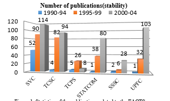 Figure 1. Statistics of the publications related to the FACTS
Actually, these statistics are reflecting the installed FACTS systems in the world. Reference [22] presented approximate results of a survey on worldwide integrated FACTS. It should be mentioned that SVC is the most exploited FACTS with a total power of 90.000MVA. While 2.000MVA are distributed on 10 incorporated TCSC into power systems, there are only 3 real networks equipped with UPFC with 250MVA of generated power.
To understand the reasons for the widespread use of SVC in comparison to the others FACTS particularly UPFC, we must look at system planner’s choices. Recognizing that the investment cost is always a considerable constraint, economical solutions for power system instability are generally preferred. The cost of a FACTS device is highly dependent on the complexity of its model which is determined by the number of semiconductors used. Thereby, consisting of two voltage source converters, UPFC has the highest cost among the various FACTS [22]. According to reference [23], it is estimated at 0.33 million$ for 1MVAR generated power while the cost of SVC is approximately 0.19 million$ and the instrument and investment costs of TCSC are estimated at 0.22 million$ for 1MVAR generated power. Thus, when the network is already equipped with SVC, we can get well-improved stability by adding TCSC and at the same time economize 0.11million$ for each MVAR generated.
Otherwise, the cost-efficiency is not always to install the least costly FACTS device, but rather to choose the appropriate one based on the type of instability problem that we want to solve. As these problems are, on the one hand, unpredictable and on the other hand, closely linked, it is required to invest in equipment which can assure the control of more than one network parameter. Currently, UPFC has the potential to act on three parameters, namely: phase angle, line impedance, and bus voltage either simultaneously or separately. So, confronted with these constraints, we thought to find a solution for network instability, combining the economical side with the wide application area and efficiency side. Hence, our idea is to create an equivalent of UPFC by joining the action of TCSC, as a series FACTS, to that of SVC which assure the shunt compensation. With this approach, power system stability is enhanced at lower cost.
3. Voltage Instability
In power system stability field, a particular interest is accorded to the control of voltage and reactive power. The main issue is to avoid voltage instability which can result in a widespread problem known as voltage collapse [7]. For this purpose and in order to guarantee the reliability and the efficiency of power system operation, the following points must be respected in voltage and reactive power control:
- Voltages of all network buses must be within the permissible interval. According to reference [24], it is specified as [0.94pu; 1.06pu] for MV network.
- The reactive power flow in transmission lines must be minimized as much as possible. This leads to reducing line losses: and .
We can illustrate the voltage instability by considering the system of Figure 2. This 2-bus network consists of a voltage source supplying a load through a transmission line.
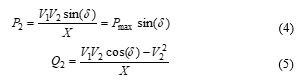
The apparent impedance at bus 2 is expressed by:
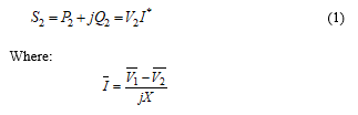
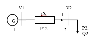 Figure 2. Equivalent model of a 2-bus system
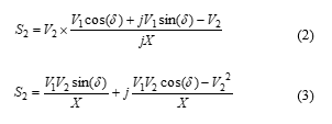
![]()
 : Busbar 1 voltageWhere :
: Busbar 2 voltage
I : Line current
X: Line reactance
: Generator internal angle
and : Active and reactive powers supplied to the load.
Equation (7) describes the evolution of the voltage at bus 2 in function of the load increase at the same bus. We can deduce that in addition to the active and reactive powers, bus 2 voltage depends on the line reactance.
4. FACTS Models
In order to compare the performances of the FACTS devices, it is required to describe their functionalities supported with mathematical models and equivalent schemes. That is what we are going to present in this subsection.
4.1. TCSC
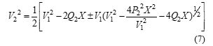
TCSC is one of the most important FACTS equipment, which has been used to modify the series impedance of the transmission line in order to improve system stability. Typically, it consists of a thyristor-controlled reactor in parallel with a fixed capacitor, which is equivalent to an adjustable reactance [25, 26]. The reactance of a transmission line equipped with a TCSC is expressed as follows:
![]() Figure 3 shows a TCSC integrated between bus j and bus k with its equivalent model while Figure 4 describes the configuration of the series FACTS.
Figure 3 shows a TCSC integrated between bus j and bus k with its equivalent model while Figure 4 describes the configuration of the series FACTS.
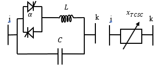 Figure 3. TCSC configuration
 Figure 4. Equivalent model of TCSC
Before the integration of the TCSC in the transmission line jk, the admittance matrix Y is given by equation (9) [27]:
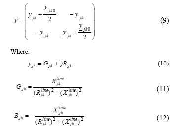 Where
Where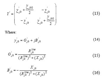
Where:
The addition of the TCSC modifies the admittance matrix as follows:
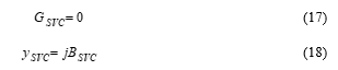
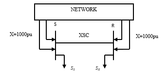 Figure 5. TCSC model on EUROSTAGOn EUROSTAG, to model a series and variable admittance, we must create two fictive buses in a transmission line and insert a current injector to each bus, as described in Figure 5. The two fictive buses must be connected to the network by lines with high reactance value to avoid injector shutdown in case of an opening line.
4.2. SVC
SVC is a static reactive power compensator whose output is adjusted for exchanging a capacitive or inductive current with the network to typically control bus voltage [28, 29]. In the steady state as well as in transient regime, this device is able to maintain voltage within the desired limits. Figure 6 shows the dynamic model of SVC. It can be modeled as variable shunt admittance with a thyristor controller. However, by neglecting the losses of SVC, we can consider it as ideal, so the admittance is purely imaginary and is described by the equations (17) and (18):
 The capacitive power injection model of SVC at the rated voltage is given by equation (19) [30]:The susceptance can be capacitive or inductive. Indeed, in the case of reactive power excess, SVC absorbs the increased amount through the inductor and in the opposite case; the capacitor covers the reactive demand.
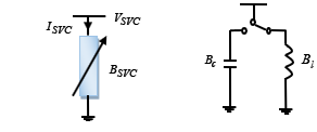 Figure 6. SVC model
![]() Where must be controlled according to equation (20):
Where must be controlled according to equation (20):
![]()
The connection of SVC to a bus j, as illustrated in Figure 7, changes the admittance matrix only at the element , in fact, the admittance of the compensator is added according to the following equation: designates the capacitive limit state while designates the inductive one. If SVC susceptance reaches its limits without maintaining the voltage of the bus where it is connected, it loses the capability of voltage control and it becomes similar to a fixed susceptance.
![]() The admittance matrix is so expressed by equation (22).
The admittance matrix is so expressed by equation (22). 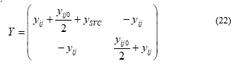
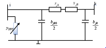 Figure 7. SVC connected to a bus
EUROSTAG adopts the model of Figure 8 and represents SVC as an impedance injector connected to a bus of the electrical network.
4.3. UPFC
UPFC is the most recognized hybrid compensator, it is the third generation of FACTS devices, it is the first and only device that has the ability to control simultaneously or separately voltage, line impedance and the phase shift of the bus voltage. UPFC consists of two transformers, one connected in series and the other in shunt with the transmission line as shown in Figure 9 [31].
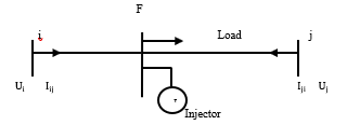 Figure 8. SVC model on EUROSTAG
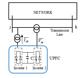 Figure 9. UPFC inserted in a power system
The inverter 2 injects the voltage which is controllable in amplitude and in phase so that it can perform the serial compensation function of the active power. On the other hand, the inverter 1 is used, through the continuous connection, to provide the active power required for the inverter 2, it serves to compensate the reactive power since it can absorb or inject the active power into the network. Indeed, UPFC allows both the active power control and the line voltage control. It can switch from one to the other function instantaneously by changing the control of the inverters separated by a capacitor.
The equivalent circuit of UPFC is represented in Figure 10 [32]. From this scheme, we can extract the active and reactive power flows of the shunt and series converters which are expressed by the equations (23) – (25)
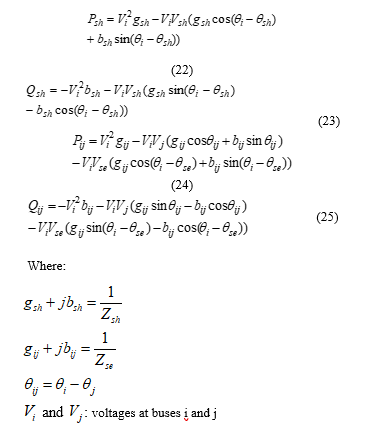
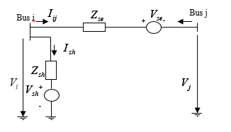 Figure 10. Equivalent circuit of UPFC
and : voltages at buses i and j
and : active and reactive power flows of the shunt inverter
and : active and reactive power flows of the series inverter
and : shunt and series voltage sources
and : shunt and series coupling transformer impedances.
The modeling of the UPFC shunt part on EUROSTAG is simple; it is represented by a current injector. As for the modeling of the series part, we must open the line where we want to insert UPFC and place at its extremities two current injectors (Figure 11). The opening of the line is assured by a high reactance value.
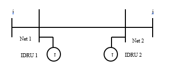 Figure 11. UPFC model on EUROSTAG
5. Proposed Approach
The main purpose of our paper is to find an economical and efficient way for sustaining voltage stability by comparing the performances of SVC-TCSC to those of UPFC. In order to achieve this, it is important to take into consideration the identification of the proper placement of the FACTS in the system.
There is a variety of methods for finding optimal solutions [19, 33]. However, in practice, the time factor is more important than optimally solving the problems so that engineers and system planners often resort to heuristic methods. Heuristic methods known also as approximate methods are used for the resolution of optimization problems. These methods guarantee to find in a polynomial time at least a good and a feasible solution, but not necessarily the optimal one [34].
There are different types of heuristic algorithms, as shown in Figure 12, among which we are interested in reduction heuristics. The principle of such a method is to simplify the problem and to reduce the domain of the solutions. This implies to define the boundaries of the problem by identifying the properties that must satisfy a good solution.
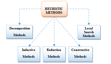 Figure 12. Types of heuristic algorithms
Figure 13 shows the flowchart of the proposed method. The normal state of the system must be obtained first of all so that we can analyze the load flow results and determine the weakest zone of the system that needs to be compensated. In this way, the location problem is simplified and the domain of solutions is reduced to the weakest zone. Based on the load flow analyses, a preliminary selection of the FACTS placement is made. Then, the system with the FACTS devices is executed. The evaluation of the selected location is performed by comparing the voltage magnitude to the specified lower and upper boundaries. A proper FACTS placement must maintain the voltage of all the buses within the permissible limits. If this criterion is not respected, another location has to be considered, and the evaluation based on the defined boundaries is repeated. Once the best location of the devices is identified, the next step is to perform the comparison between the proposed FACTS. The comparison takes into consideration the voltage magnitude, the oscillations, and the power flows.
With this method, we can get satisfactory results and avoid complicated and slow routines of the optimization methods.
6. Simulation
6.1. Test System
The proposed case study is the classical system IEEE 14-bus network, it consists of:
- Two generator buses and eleven load buses.
- Fifteen transmission lines.
- A three-winding transformer and two step-up transformers with two windings.
- Three synchronous compensators connected to buses 3, 6 and 8.
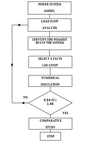 Figure 13. Flowchart of the proposed method.
All data relating to this test network are extracted from reference [32] and we used EUROSTAG software package [35] for the simulations. This software is a powerful tool dedicated to dynamic simulations. Its major advantage is the high rapidity of its algorithm. Irrespective of the nature of the disturbance and the system size, it can rapidly visualize the behavior of the network until it returns to an equilibrium state. Furthermore, this simulation is not accompanied by any deterioration in the accuracy of the calculations. In addition, it gives the possibility to define the modeling level adapted to the type of the performed study.
6.2. Simulation Results
6.2.1. Identification of FACTS Location
To compare the performances of UPFC and the proposed SVC-TCSC, first of all, it is mandatory to identify the appropriate placement of the FACTS. This step has to provide a firm basis for comparison. Therefore, we plan a step change in load at time t= 200s from 5% of the initial load by a step of 5%. The procedure continues until reaching the maximum loading capability of the system.
The results of the base state signaled that bus 14 has got the lowest voltage amplitude as shown in Figure 14; hence we summarized the voltage levels of bus 14 during various step changes in Table 1.
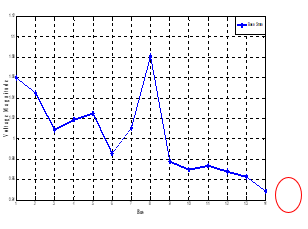 Figure 14. Voltage profile of IEEE 14-bus system in normal state
Table 1. Network behavior under incremental load increase.
| Network Settings | Load Increase in % | |||||
| 5% | 10% | 20% | 25% | 30% | 33% | |
| U14
(pu) |
0.966 | 0.962 | 0.952 | 0.948 | 0.946 | Voltage collapse |
| State System | Stable
|
|||||
We note the occurrence of a voltage dip in bus 14, which is increased as more the loads are augmented. The voltage level is still acceptable and the network is maintaining its stability until 32% of load increase. When reaching the case of 33%, EUROSTAG fails to execute the simulation which means that the system is collapsing.
After identifying the weakest bus of the system, we make a preliminary selection of the FACTS location. Hybrid or series controller both must be integrated through a transmission line. According to the network architecture, as schematized in Figure 15, bus 14 is related to bus 13 and bus 9, so we have two possibilities to place the device.
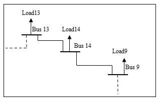 Figure 15. Scheme of the architecture of the IEEE 14-bus system
First of all, we integrate UPFC in the middle of line 13-14. Then, we apply an increase of 20% of the total load of the system. As shown in Figure 16, there is no improvement in the magnitude of bus 10 voltage. In addition, lower amplitudes equal to 0.925pu and 0.977pu are obtained respectively in bus 14 and bus 9, compared to the uncompensated system. Thus, it is concluded that line 13-14 is not a good location for the FACTS to perform the comparative study.
Now, we integrate UPFC through line 9-14 and we rerun the system. A meaningful improvement of the voltage magnitude is observed. According to Figure 16, UPFC has increased the voltage amplitude of bus 14 from 0.952pu to 0. 1.007pu with less severe oscillations, bus 10 from 0.976pu to 0.985pu and bus 9 from 0.982pu to 0.991pu. As we have got satisfactory results, the line 9-14 is retained as a good placement to insert the proposed FACTS and then to compare their potentialities.
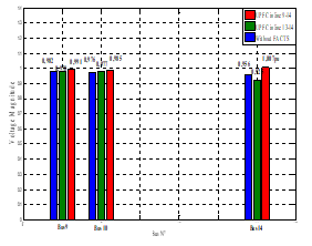 Figure 16. Voltage profile with different UPFC locations.
6.2.2. Performance comparison between the FACTS
We connect UPFC and SVC-TCSC to the network, separately. Firstly, UPFC was integrated into the middle of line 9-14 with a capacity of 60MVAR for each one of its inverters, and then, with keeping the same dimensions, we inserted TCSC through the line 9-14 and SVC to bus9.
Based on the results of the prior section, we apply a total load increase of 30% of the initial load. In this case, the test network is under heavy loaded conditions.
We are interested in the comparison, to the evolution of bus voltage as well as the active and reactive power flows in transmission lines.
Taking bus 14 as an example as shown in Figure 17, it can be seen that both UPFC and SVC-TCSC have a bearing on the voltage magnitude by increasing it significantly, while it was under the minimum acceptable value before compensation. However, UPFC showed a higher capability of enhancing voltage level, from 0.90pu to 0.96pu. In addition, we obtained a rapid damping of oscillations after only 7s either by UPFC or SVC-TCSC.
The impact of the FACTS on the oscillatory regime is clearer in the voltage curve of bus1, plotted in Figure 18. Nonetheless, we note that the damping action of SVC-TCSC is more considerable compared to that of UPFC, in fact, it reduced the highest oscillation from 1.08pu to 1.071pu and rapidly established the steady state with well-amortized oscillations.
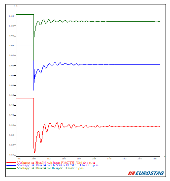 Figure 17. Voltage of bus14 with and without FACTS.
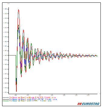 Figure 18. Voltage of bus1 with and without FACTS.
According to the results of Table 2, an excellent enhancement in the active power has been observed with the action of UPFC. However, we didn’t note any important change in its level when used SVC-TCSC. As for the reactive power flow, it encountered a considerable decrease by using UPFC; it was decremented from 5.7 MVAR to 2.5MVAR through the line 9-10 as an example. This was observable also when introducing the combination SVC-TCSC. The amount of reactive power in line 6-12 is reduced by about 12% and in line 1-2, from 20MVAR to 19.2MVAR. Nevertheless, we recorded an increase of 10.5% in the transmitted MVARs across line 9-10.
Figure 19 shows the active power transmitted in line 1-2 with and without FACTS. When focusing on the transient regime, it must be mentioned that even in the temporal evolution of powers, the damping action of SVC-TCSC is more efficient; it gives more attenuated oscillations and joins the stable state in a shorter time.
Table 2. Active and reactive power flows with and without FACTS.
| Simulat- ion case | Line 9-10 | Line 1-2 | Line 6-12 | |||
| Active Power MW | React. Power MW | Active Power MW | React. Power MW | Active Power MW | React. Power MW | |
| Without FACTS | 8.3 | 5.7 | 209 | 20 |
9.8 |
3.4 |
| With SVC-TCSC | 8.3 | 6.3 | 209 | 19.2 |
10 |
3 |
| With UPFC | 9.2 | 2.5 | 216 | 18.1 | 10.8 | 1.5 |
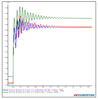 Figure 19. Active power flow in line 1-2 with and without FACTS.
7. Conclusion
This paper presented a hybrid method for voltage stability enhancement using SVC and TCSC. The advantage of the proposed approach is the lesser cost of achieving a safe power system operation. The IEEE 14-bus system was utilized to test the performance of the combination SVC-TCSC and compare it to the UPFC, the most pricey and multi-functional FACTS. The identification of the best placement of the FACTS devices was performed using a simple heuristic method. The simulation results demonstrated that the hybrid FACTS based on SVC and TCSC is able to significantly improve the voltage profile of the whole network in addition to the satisfactory action in amortizing the oscillations. The findings are encouraging to rather improve the performance of the SVC-TCSC in controlling power flow in lines and introduce other techniques for optimal location
- Singh, “Applications of FACTS Controllers in Power Systems for Enhance the Power System Stability: A State-of-The-Art,” International Journal of Reviews in Computing, Vol. 6, 15th July 2011.
- Kundur, “Power system stability and control,” McGraw-Hill, Inc., 1993.
- Damor, . D. Patel, V. Agrawal, H. Patel, “Improving Power System Transient Stability by using FACTS Devices,” International Journal of Engineering Research & Technology (IJERT), Vol. 3, Issue 7, July 2014.
- Rath, B. Sahu, P. Dash, “Power System Operation and Control using FACTS Devices,” International Journal of Engineering Research & Technology (IJERT), Vol. 1, Issue 5, July 2012.
- Dheebika, R. Kalaivani, “Optimal Location of SVC, TCSC and UPFC Devices for Voltage Stability Improvement and Reduction of Power Loss using Genetic Algorithm,” International Conference on Green Computing Communication and Electrical Engineering (ICGCCEE), 2014.
- Ahmad, F.M. Albatsh, S. Mekhilef, H. Mokhlis, “An Approach to Improve Active Power Flow Capability by Using Dynamic Unified Power Flow Controller,” IEEE Trans., 2014.
- Gupta, P.R. Sharma, “Static and Transient Stability Enhancement of Power System by Optimally Placing UPFC (Unified Power Flow Controller),” IEEE trans., 2013.
- Jmii, A. Meddeb, S. Chebbi, “Efficiency Limits of SVC in Improving Voltage Stability,” 3rd Inter. conf. (GEEE), April, 2016, Hammamet, Tunisia.
- Sivachandran, T. Hariharan, R. Pushpavathy, “Improvement of Power System Stability using D-FACTS Controllers: A Review,” ARPN Journal of Engineering and Applied Sciences, Vol. 10, No. 2, February 2015.
- Rao, P. Chanti, N. Lavanya, S. Sekhar, Y. kumar, “Power System Stability Enhancement Using Fact Devices,” International Journal of Engineering Research and Applications, pp.339-344, Vol. 4, Issue 4( Version 1), April 2014.
- Kamarposhti, M. Alinezhad, H. Lesani, Nemat Talebi, “Comparison of SVC, STATCOM, TCSC, and UPFC Controllers for Static Voltage Stability Evaluated by Continuation Power Flow Method,” IEEE Electrical Power & Energy Conference, 2008.
- Motiebirjandi, D. Fateh, “Optimal placement method of multi UPFCs to damp power system oscillations,” International Transactions on Electrical Energy System, 2017.
- Benaissa, S. Hadjeri, S.A. Zidi, “Impact of PSS and SVC on the Power System Transient Stability,” Advances in Science, Technology and Engineering Systems Journal, pp. 562-568, Vol. 2, No. 3, 2017.
- Meddeb, H. Jmii, S. Chebbi, “UPFC and SVC Devices for Transient Stability Enhancement,” 4th International Conference on Automation, Control Engineering and Computer Science (ACECS) Proceedings of Engineering and Technology – PET, pp.82-87, Vol.19, 2017.
- Titus, B.J. Vinothbabu, I. Nishanth, “Power System Stability Enhancement under Three Phase Fault with FACTS Devices TCSC, STATCOM and UPFC,” International Journal of Scientific and Research Publications, Vol. 3, Issue 3, March 2013.
- Bhattacharyya, V.K. Gupta, S. Kumar, “UPFC with series and shunt FACTS controllers for the economic operation of a power system,” Ain Shams Engineering Journal, 2014.
- Varma, “FACTS Devices for Stability Enhancements,” International Conference on Green Computing and Internet of Things, 2015.
- Pandey, B. Bag, “A Comparative study on UPFC and SVC towards Voltage Profile improvement of a Grid Connected Distributed Generation System,” IEEE tran.s, 2015.
- Stefanov, A. Savić, G. Dobrić, “Power System Optimization Using Parallel Scenario Algorithm,” IEEE International Energy Conference, 2014.
- Jmii, A. Meddeb, S. Chebbi, “An approach for improving voltage stability by combination of SVC and TCSC,” 7th International Conference on Sciences of Electronics, Technologies of Information and Telecommunications (SETIT), pp.134–141, 2016.
- A. Abido, “Power System Stability Enhancement using FACTS Controllers: A Review,” The Arabian Journal for Science and Engineering, vol.34, no1B, Apr 2009.
- P. Zhang, C. Rehtanz, B. Pal, “Flexible AC Transmission Systems: Modeling and Control,” 2nd Edition, Springer, Feb 2012.
- Sadi, S. Ali, “A Comprehensive Analysis Of Transient Stability Enhancement Methods Of Electric Power System,” IEEE trans, 2015
- Characteristics of voltage in public distribution networks, Standard EN 50160, 2007.
- Zellagui, H.A. Hassan, A. Chaghi, A. Ghorbani, “A Comparative Study of Ground Fault Analysis for a Practical Case of a Transmission Line Equipped with Different Series FACTS Devices,” Automatika Journal, pp 262–274, 2015.
- Murali, M. Rajaram, N. Reka, “Comparison of FACTS Devices for Power System Stability Enhancement,” International Journal of Computer Applications, Vol. 8, No.4, October 2010.
- Amrane, M. Boudour, M. Belazzoug, “A new hybrid technique for power systems multi-facts optimization design,” International Transactions on Electrical Energy Systems, 2014.
- V. The., K.L. Minh., T.T. Quoc, N.B. Khue., “FACTS devices applications on power system to improve the angle stability,” IEEE, 2006.
- Varma, “FACTS Devices for Stability Enhancements,” IEEE trans., 2015.
- Kumkratug, “Application of Lyapunov Theory and Fuzzy Logic to Control Shunt FACTS Devices for Enhancing Transient Stability in Multimachine System,” Journal of Electrical Engineering & Technology, vol. 7, no. 5, pp. 672-680, 2012.
- Haque, “Evaluation of First Swing Stability of a Large Power System with Various FACTS Devices,” IEEE Transactions on Power Systems, Vol. 23, No. 3, August 2008.
- Milano, “Power System Modelling and Scripting,” Springer, ETSII, University of Castilla – La Mancha 13071, Ciudad Real Spain 2010.
- Dubey, S. Dixit, G. Agnihotri, “Optimal Placement of Shunt FACTS Devices Using Heuristic Optimization Techniques: An Overview,” International Conference on Communication Systems and Network Technologies, 2014.
- Marti, G. Reinelt, “Exact and Heuristic Methods in Combinqtorial Optimization,”Available:https://books.google.tn/books?id=4Lk8pPYYI3cC&printsec=frontcover&hl=fr#v=onepage&q&f=false.
- Eurostag, Eurostag Software Release Notes, Tractebel-EDF, Release 5.1, Dec 2010.