Modelling of the resistance heating of the moving molybdenum sheet

Adv. Sci. Technol. Eng. Syst. J. 3(1), 130–134 (2018);
 DOI: 10.25046/aj030116
This article describes the modeling procedure of a direct resistive heat model of the molybdenum sheet and its simulation with electrodes made from various materials. The main characteristic of the proposed model is its dynamic behavior, because model considers the movement of the molybdenum sheet. The simulation results are mutually compared and the optimal material parameters are selected. The development of the model, in which the movement of molybdenum sheet is considered is used for determination of optimal movement speed of the molybdenum sheet in order to achieve requested temperature. The presented model can be also used for determination of optimal electrode materials and its geometrical properties/shape.
1. Introduction
This paper is an extension of work originally presented in Electrical Power engineering 2017 [1]. This article discusses the usage of finite element method for the development of a resistive heating model of the molybdenum sheet. The model is designed for the needs of the development of the equipment for the heating and shaping the molybdenum sheets into molds. The mentioned molds are used as containers for horizontal crystallization of the sapphire single crystal. Molybdenum is one of the few materials suitable for this purpose in a view of the long-term high-temperature load of the mold. The mold is exposed to the temperature gradient of up to 100 °C./ mm at the maximum temperature of 2150 °C. in the longitudinal direction of the container, where in one part is the melt and in the adjacent part is the corundum as an already growth product, i.e. single sapphire crystal. Based on the extreme conditions during the process, it is crucial to not decrease the mechanical abilities during the shaping process of the mold. For that purpose, the structural changes and possibilities of avoiding them by properly set pre-heating respectively heating/cooling system of Mo sheets need to be predicted. Currently, the molds are made of molybdenum sheet having a thickness of 0,5 mm, made by powder metallurgy technology, i.e. by plastic deformation and sintering procedure. Specifically, the molybdenum sheet Grade M1 corresponding to the American standard ASTM B386 or GB 3877, where the chemical composition is approximately the same. [2-5]
2. Basic simulation model
The simulation model is developed in COMSOL environment as a 3D model with the options for reconfiguration the mutual position of electrodes, the electrode material and the pressure on the electrodes. The model is composed of the molybdenum sheet and two electrodes. The molybdenum sheet is modeled as a block (domain) with a wanted width(a), depth(b) and thickness(c) and electrodes are modeled as cylinders with a wanted diameter(d), height(h) and distance(x) between them. The geometry (Fig.1.) is then complemented by physic setup. The Multiphysics “Joule heating (JH)” is used for the model. This Multiphysics is formed by the connection of “Electrical circuit (EC)” physic and “Heat transfer in solid (HTS)” physic. The physic “Electrical circuit” is used to set up the value of input current trough top boundary of one electrode and grounding through the top boundary of the other electrode. Within the EC module, the required contact pressure applied to the electrodes and the roughness of the contact between the electrode and Mo sheet can be adjusted. The HTS is used to set up parameters as initial temperature of the system and the method in which the temperature is transferred to the surrounding area. The proper function of the model is achieved by setting the spherical domain with a diameter of one meter, which is filled with air. All simulations are the set as time domain simulation, so we can determine the influence of studied materials on the speed of the heating of the Mo sheet. [6-9]
As it has been already mentioned, the model is reconfigurable, but for means of this paper the following geometrical parameters are set: Parameters of molybdenum sheet (based on manufactured molybdenum sheets [10,11]): 1000/300/1 (a/b/c) mm, parameters of electrodes: 20/50 (d/h) mm, the electrodes distance: 100 (x) mm. The electrodes are pressed to the Mo sheet with a pressure of 0.3 MPa. For the electrode’s material study, three classes of materials based on the electrical conductivity of the electrodes are defined (lower than Mo, Mo and higher than Mo). The electro-thermal parameters of the basic model are defined in TABLE I. The model needs to be particularly accurate in the molybdenum sheet domain. For that purpose, the temperature dependencies of electro-thermal parameters of molybdenum are implemented, specified by the manufacturer “PLANSEE” (Fig.2-4.).
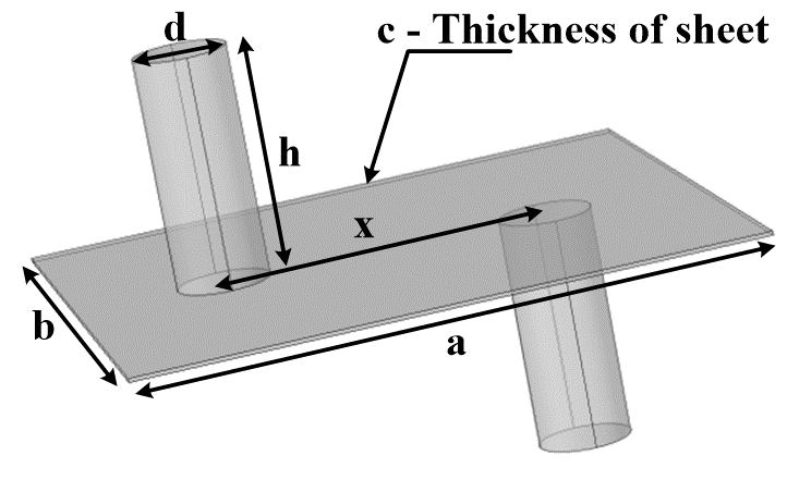 Fig.1: Representation and definition of Mo sheet model
Table 1: Electro-thermal parameters used in simulations
| Material | Parameter | ||||
| Electrical cond. [S/m] | Relative perm.
[-] |
Thermal cond. [W/(mK)] | Specific
heat capacity [J/(kgK)] |
Density
[kg/m^3] |
|
| Molybdenum (20 °C ) (293.15 K) | 17.9e6 | 1 | 142 | 254 | 10280 |
| Class I.
Lower El. Con. |
σMo/10 | 1 | 400 | 385 | 8700 |
| Class II.
Equivalent El. Con. |
σMo | 1 | 400 | 385 | 8700 |
| Class III.
Higher El. Con. |
σMo*100 | 1 | 400 | 385 | 8700 |
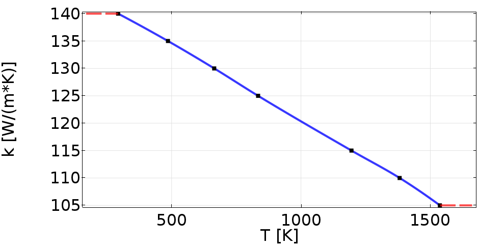 Fig.2: Thermal dependence of thermal conductivity of molybdenum used in simulations
The mentioned JH module of the COMSOL environment uses well-known equations for modeling a heat transfer in solid materials (1).
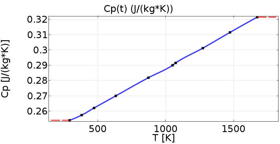 Fig.3: Thermal dependence of specific heat capacity of molybdenum used in simulations
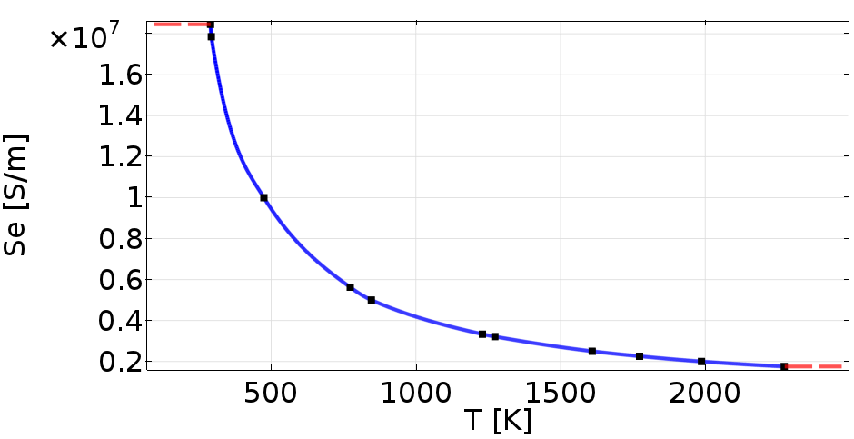 Fig.4: Thermal dependence of electrical conductivity of molybdenum used in simulations
Where “ρ” is the density of the modeled material, “CP” is specific heat capacity of the material, “k” is thermal conductivity of the material and “Q” is a heat source.
In this case, the heat source “Q” is determined by Joule-Lenz law of resistive loses in material structure due to the current flow through this structure.
3. Simulation results I.
Based on [6] the wanted temperature of Mo sheet is at a level between 1000 K to 1200 K. At those levels, the Mo sheet can be easily bendable. The simulation is done for before mentioned electrode’s material classes (TABLE I.) not for specific material. The input current of the system is selected within the interval from 1000 A to 1400 A. The results are compared in a way of temperature distribution within Mo sheet domain and speed of the heating process. Fig.5. shows actual simulation model with geometrical parameters defined in the previous paragraph.
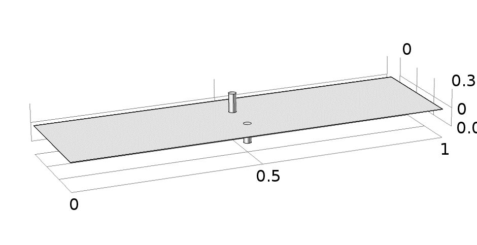 Fig.5: Model of Mo heating with given geometrical parameters
The simulation is done with electrodes placed in the middle of the longer side of the sheet while the distance between electrodes is set to 100 mm. The following results are displayed as the temperature in the point in the middle of the sheet’s volume and temperature distribution in the cutline between electrodes (middle of the Mo sheet) as can be seen at Fig.6.
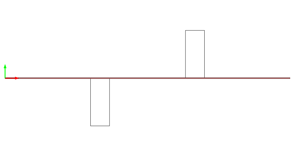 Fig.6: Line for result extraction (Temperature distribution)
Fig.7. shows mentioned results for the first class of electrode’s material, which has lower electrical conductivity than Molybdenum. The wanted temperature of 1000 K (Fig.7. up) was achieved in 75 s for lowest current (1000 A) and in 4 s for highest simulated current (1400 A). The wanted temperature interval is marked as black dashed lines in Fig.7,8,9 (up). The second part of the graph (Fig.7.middle) shows temperature distribution (based on Fig.6.) for different current values, while the time when the desired temperature value was achieved (1000 K) is considered. The last part of the graph shows temperature distribution within whole Mo sheet with the chosen current flow. Fig.8. and Fig.9. have the same purpose as Fig.7., but other material types are considered. For second electrode’s material (Se=17.9e6 S/m) can be seen that wanted temperature was achieved in 95 s for current value of 1400 A.
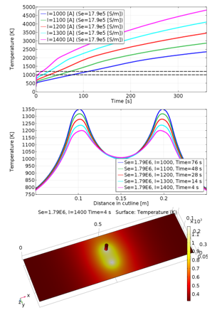 Fig.7: Results for first electrodes material type (Se = 17.9e5 [S/m])
In case of third material the heating process was much slower (the major part of heat is produced through the direct resistive heating, while in first two cases there was also considerable influence of indirect resistive heating), wanted temperature was achieved in 164s for current 1400 A and it can be said that minimal current needed to achieve wanted temperature in given time is 1200 A.
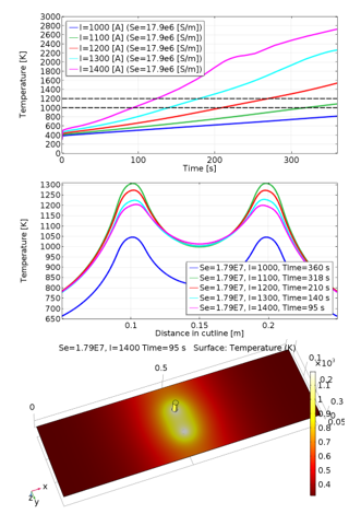 Fig.8: Results for second electrede’s material type (Se=17.9e6 [S/m])
4. Model of sliding molybdenum plate
For simulation of sliding molybdenum sheet the same settings of physics and geometry are used as within the basic model (previous part), but for the shift of the Mo sheet a special script in Matlab language is developed, which basically simulates the heating in a loop with the different initial position of electrodes. For the required temperature distribution, which is different for each step of the simulation, the molybdenum sheet domain is divided into subdomains (blocks) (Fig.10.). Within individual subdomains, the average temperature is defined (volumetrically) from previous simulation step and next simulation step is simulated with given electrodes shift. Each domain is within script defined as a 3D object with given length, width and height. These geometrical parameters are computed from geometrical parameters of whole Mo plate and from a wanted number of the subdomain in every direction of Mo plate. Mathematically, this model is described as the basic simulation model with equation 1 and by Joul-Lenz law for heat source of the modeled physic.
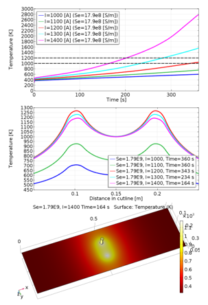 Fig.9: Results for third electrode’s material type (Se=17.9e8 [S/m])
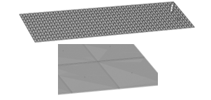 Fig.10: Model of Mo heating with subdomains
5. Simulation results II.
The simulation is done for the second class of materials with electrical conductivity value close to Mo sheet, in which the temperature distribution was most uniform. Based on the optimal speed of the heating process and distribution of heat within Mo sheet, the input current of 1400 A is applied. It needs to be mentioned that this part of the model was created purely for verification of the proposed modeling process and thus, it does not consist any actual comparison with measurement. For that reason, a quite large (120 mm) electrodes shift is chosen for simulation. Model of the Mo sheet is composed of (32x10x2) subdomains and it is simulated in 5 steps with total electrodes shift of 600 mm in 100 s. The results shown in fig. 11 demonstrates the functionality of the proposed model (chapter 4), while each step of simulation is defined two times. The initial time (0 s) is representing initial temperature setting within each subdomain with new electrode position. The secondary time (20 s) is representing end time for each step and for the temperature distribution needed what is needed for next step’s initial condition. Based on the results of the individual simulation steps, it can be said that the modeling process is suitable for this application and may be applied also in other cases/studies.
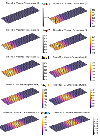 Fig.11: Simulation results for given parameters
6. Conclusion
In this paper, the design of thermal finite element simulation model of Mo sheet was described. The main aim was to target exact modeling of thermal field in the structure of Mo sheet, while multiple material properties of heating electrodes where considered because resistive heating is considered within the proposed paper.
The presented model had the possibility of the reconfiguration of the electrode material, the electrodes distance, the electrode geometry as well as Mo sheet geometry. Also, Multiphysics is considered, whereby various values of electric current have been applied during experiments. For these purposes, several types of simulation models were developed. The main problem during the investigation is the proper definition of the material properties of Mo sheets. Each manufacturer has different material composition. Therefore, the simulation model has to have the possibility of reconfiguration in order to meet experimental results, which have been made within previous researchers. Consequently, the presented model shall serve for optimization procedures, because experimental investigation mostly acts as time-consuming. Based on investigated configuration it can be claimed that there are possibilities of improvement in speed of heating (point-heating) as well as possibility of pre-heating (line-heating) by using electrodes from different materials.
Second approach o presented paper was focused on the design of the model, which will consider a dynamic change of the heated place within Mo sheet, i.e. translation move was applied. Various software products have limitations regarding the dynamic movement of the investigated sample, therefore special script in MATLAB environment was developed. With the use of this approach, each iteration of the simulation accepts previous results, which are repeatedly implemented within the computation solution.
Given proposal of the solution was required due to future works, which will be focused on the design of multi-physics simulation model of Mo sheet heating and molding system, where high-validity simulation models are expected to be used namely for further investigations of mechanical parameters and other molybdenum restrictions.
Conflict of Interest
The authors declare no conflict of interest.
Acknowledgment
The authors wish to thank Slovak grant agency APVV for the project no. 0396-15 – Research of perspective high-frequency converter systems with GaN technology and for the project no. 14-0284 – Study of Utility Properties of Formed Molybdenum Sheets Applicable for Horizontal Crystallization of Sapphire Single Crystal.
- Pavelek, M. Frivaldsky, P. Spanik, T. Donic, “Electrothermal model of resistance heating of molybdenum sheet” in EPE 2017, Kouty nad Desnou 2017. https://doi.org/10.1109/EPE.2017.7967262
- Hargaš, M. Hrianka, J. Lakatos, D. Koniar, “Heat Fields Modeling and Verification of Electronic Parts of Mechatronics Systems” Metalurgija 49(2), 268 – 272, 2012. https://doi.org/10.5755/j01.eee.123.7.2371
- Karban, F.Mach, I.Doležel, “Hard-couple model of local direct resistance heating of thin sheets” Journal of Computational and Applied Mathematics 236(18), 4725-4731, 2012. https://doi.org/10.1016/j.cam.2012.02.036
- Dughiero, M.Forzan, C.Pozza, E. Sieni, “A translational couple electromagnetic and thermal innovative model for induction welding of tubes” IEEE Transactions on Magnetics 48(2), 483-486, 2012. https://doi.org/10.1109/TMAG.2011.2174972
- K.Mori, S. Maki, Y.Tanaka, “Warm and Hot Stamping of ultra-high tensile strenght sheets using resistance heating” CIRP Annals-Manufacturing Technology 54, 209-212, 2005. https://doi.org/10.1016/S0007-8506(07)60085-7
- Maki, Y. Harada, K.I. Mori, H. Makino, “Application of resistance heating technique to mushy state forming of aluminium alloy” Journal of materials processing technology 125, 477 – 482, 2002.
- Cuntala, A. Kondelova, O. Hock, M. Pridala, “Electro-Thermal Modeling of Power LED Using COMSOL Environment” in ELEKTRO 11TH INTERNATIONAL CONFERENCE, Slovakia, 2016.
- Hrianka, L. Hargaš, J. Lakatš, D. Koniar, “Modeling, Simulation, and Verification of Heat Transfer in Power Transistor Cooler” Metalurgija 2 49(), 283 – 287, 2012.
- Mori, S. Maki, Y.Tanaka, “Warm and Hot Stamping of ultra-high tensile strenght sheets using resistance heating” CIRP Annals-Manufacturing Technology, 54(), 209-212, 2005.
- Plansee Group, https://www.plansee.com/en/index.html [10.11.2017]
- ED FAGAN INC., MACHINING GUIDE, http://www.edfagan.com/litPDF/Machining_Guide_All_Materials.pdf [10.11.2017]