Performance Analysis of Regenerative Braking in Permanent Magnet Synchronous Motor Drives

Adv. Sci. Technol. Eng. Syst. J. 3(1), 460–466 (2018);
 DOI: 10.25046/aj030156
This paper describes the design and analysis of a regenerative braking system for a permanent magnet synchronous motor (PMSM) drive for electric vehicle (EV) applications. First studied is the principle for electric braking control of a PMSM motor under field-oriented control (FOC). Next, the maximum braking torque in the regeneration mode as well as the braking torque for the maximum regeneration power, respectively, are deduced. Additionally, an optimum switching scheme for the inverter is developed with the objective of maximizing energy recovery during regenerative braking to the DC-bus capacitor. The integration of an ultra-capacitor module with the battery allows for the efficient and high power transfer under regenerative braking. It was important to manage the power flow to the DC-bus as this is a key issue that affects the efficiency of the overall system. Finally, the amounts of braking energy that can be recovered, and the efficiency with which it can be returned to the battery/ultra-capacitor, is analyzed for a PMSM coupled with a DC motor as the load. The results of the analysis are validated through experimentation.
1. Introduction
Interest in regenerative braking is growing drastically nowadays; as the market is slowly transitioning to electric vehicles (EV) instead of the traditional vehicles that run on fossil fuels. Regenerative braking (RB) utilizes the kinetic energy generated by the motor during the deceleration, or braking, process. Therefore, recovering the braking energy is an effective approach for improving the driving range of an EV [1]-[4]. Usually, within traditional vehicles, all of the braking energy is lost in the form of heat due to friction losses. In RB, the motor acts as a generator and the kinetic energy is harvested by applying the proper switching schemes to the power converter switches. This harvested energy can be used to charge the vehicle’s battery, or stored in an ultracapacitor bank [5]-[8]. A hybrid energy storage system can be used to alternate power generation and storage between an ultracapacitor and a battery, depending on the required power. Knowing the parameters of the system is essential to building a clear idea regarding the amount of energy harvested as opposed to that being generated.
The permanent-magnet synchronous motor (PMSM) is widely adopted as the traction motor in electric vehicles (EV) due to its high efficiency and high torque density. Vector control, also called field-oriented control (FOC), is a popular and powerful method in electrical drive applications. This control strategy is used to effectively control the PMSM motor torque and flux in order to force the motor to accurately track the command trajectory regardless of machine and load parameter variations, or any other external disturbances [9]. Electric braking control of the PMSM based on FOC is realized by requesting a negative q-axis current according to the braking torque demanded. The maximum amount of current produced while braking is calculated depending on many variables, including the motor speed and input voltage [10].
This paper is an extension of work originally presented in ICMSAO’17, where regenerative braking was analyzed for a DC motor with battery/supercapacitor energy storage [11]. The maximum amount of current produced by the DC motor while braking was calculated depending on the system variables such as motor speed, armature resistance, and input voltage. The theoretical analysis was next validated by experimental results. The effect of varying the duty cycle of the braking signal was also studied to find the optimal duty cycle that gives the best efficiency in regenerative energy harvesting.
In this paper, electric braking is first analyzed for the PMSM under Field Oriented Control (FOC). Next, a dedicated maximum Energy Recovery Switching Scheme (MERSS) is developed to control the inverter switches during regenerative braking to maximize energy recovery. Regenerative braking energy calculations are confirmed by experimental results on a prototype PMSM motor drive system. The harvested energy is stored into the DC-bus capacitor. The efficiency with which energy can be returned to the ultracapacitor is analyzed for the FOC scheme and the MERSS. The analysis, benefits, limitations and experimental results of each control strategy are provided.
This paper is divided into 5 sections; section 2 presents the concept of regenerative braking under FOC and provides some theoretical analysis of the required motor current during this mode of operation. Section 3 presents the maximum energy recovery switching scheme. Section 4 presents the experimental results and discussion when braking the PMSM under FOC and MERSS. Finally, the conclusion is presented in Section 5.
2. Regenerative Braking of the PMSM Under FOC
In conventional passive dynamic braking the kinetic energy of electric machines is dissipated through the armature coils and the additional braking resistors. The principle of the regenerative braking with the voltage-source inverter is similar to that of the conventional dynamic braking, however; the additional resistors are eliminated and no additional power switches are used.
According to the driving conditions, the braking process can be classified as either constant speed braking or variable speed braking. The constant speed braking is usually required during the downhill road driving, while the variable speed braking often occurs during the general deceleration process.
2.1. System Setup
Figure 1 shows the general topology used in electric vehicle applications with hybrid energy storage, where the mechanical load is typically coupled to a Permanent-Magnet Synchronous Machine supplied by a battery source through an inverter. An ultracapacitor module is used as an auxiliary power source connected through a bi-directional DC-DC converter to the DC-link, thus making it possible to obtain an optimized charge/discharge operation mode.
2.2. Regenerative Braking principle of the PMSM
The FOC scheme for the PMSM is shown in Fig. 2. In FOC, the stator phase currents are measured and converted into a complex vector. This current vector is then transformed to a coordinate system rotating with the rotor of the machine.
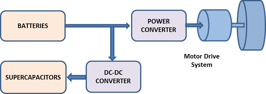 Figure 1: Topology of the Battery-Ultracapacitor Energy Storage System
The real x-axis component of the stator current vector id, in this rotor flux-oriented coordinate system, is used to control the rotor flux linkage. The imaginary y-axis component is used to control the motor torque. For the PMSM, maximum torque–current control can be achieved by holding the d-axis current at zero .
Electric braking control, based on FOC, is realized by requesting a negative q-axis current according to the braking torque demanded, or by controlling the speed to follow a ramp reference and gradually approach zero [6].
The input power and the electromagnetic power can be expressed as
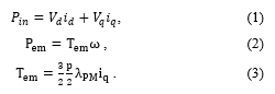 where, and are the d-axis and q-axis current components, and are the d-axis and q-axis voltage components, w is the motor speed, is the electromagnetic torque, is the permanent magnet flux, and is the number of poles.
The electric machine power losses are given as
![]() where, is the per-phase stator resistance. By balancing the input and output power
where, is the per-phase stator resistance. By balancing the input and output power
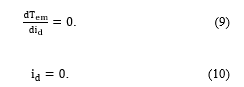
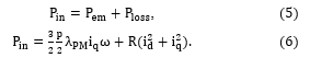 To find the regions of regenerative braking, is set to 0. This means that no power is being drawn from the DC source.
Next an expression for in terms of can be found
![]() The equivalent electromagnetic torque is given as
The equivalent electromagnetic torque is given as
![]() This equation describes the electromagnetic torque inside the regenerative braking region. To find the boundaries of this region, the above equation is solved for the maximum and minimum braking torque.
This equation describes the electromagnetic torque inside the regenerative braking region. To find the boundaries of this region, the above equation is solved for the maximum and minimum braking torque.
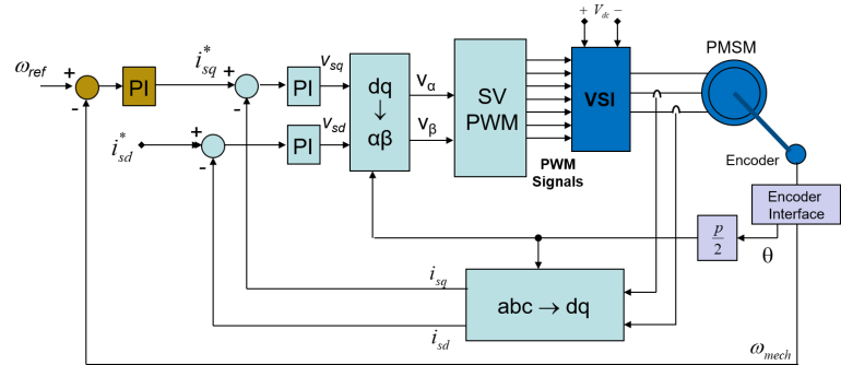 Figure 2: Field Oriented Control Scheme of the PMSM
 Substituting this result in equation (7) gives
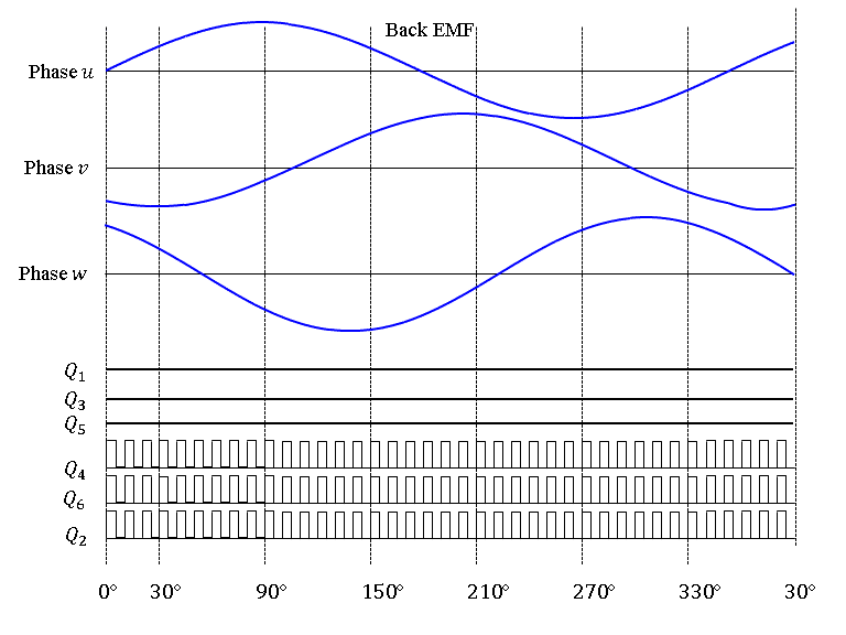
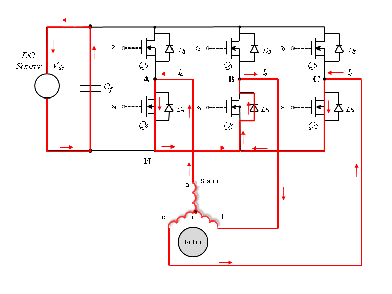
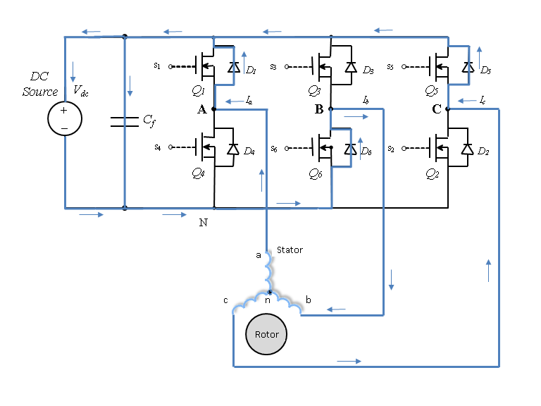 Figure 3: Regenerative braking scheme. (a) Emf and PWM switching signals, (b) Current flow during ON-Time and 0-30° period. (c) Current flow during OFF-Time and 0-30° period
![]() The equivalent electromagnetic torque is then given by
The equivalent electromagnetic torque is then given by
![]() This equation defines the minimum electromagnetic torque needed by the PMSM to operate the machine in the regenerative braking region.
This equation defines the minimum electromagnetic torque needed by the PMSM to operate the machine in the regenerative braking region.
Next, to find the maximum regenerative braking current absorbed, the input power is minimized.
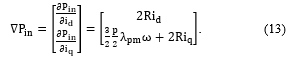 The minimum power is obtained by setting this gradient to zero and solving for both variables, and .
 The equivalent electromagnet torque generated by these current commands is given by
![]() This torque guarantees maximum absorbed current by the DC source during regenerative braking.
This torque guarantees maximum absorbed current by the DC source during regenerative braking.
3. Regenerative Braking with the Maximum Energy Recovery Switching Scheme (MERSS)
The switching scheme of the inverter is developed with the objective of maximizing energy recovery during regenerative braking. The idea is to utilize the motor phase inductors along with the inverter switches, functioning as a boost converter and allowing the phase currents to reverse their direction to flow back to the DC-bus capacitor [12], [14]. Regenerative braking is achieved by controlling only the lower switches through PWM and switching OFF all of the upper switches as shown in Fig. 3. In this mode of operation, the three lower switches are controlled with the same PWM command signal. During the ON-time, a path is provided for the phase current to flow in the negative direction through the closed switch, or in the positive direction through the free-wheeling diode depending on the polarity of the back emf.
Figure 3a shows the phase relationship between the back EMF, armature current, and the switching signals. Figure 3b and Figure 3c both show the closed loop path of the 3-phase currents during the 0-30s time interval of each cycle. During the OFF-time, the phase currents must maintain their direction and are therefore forced to flow through an alternate path created by the upper free-wheeling diodes, and then back to the DC-bus capacitor. In this time period, regenerative braking is achieved and the capacitor is charged by the recovered electrical energy.
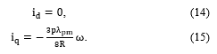
4. Experimental Testing and Discussions
In this section, experimental results of the regenerative braking process are analyzed to confirm the theoretical analysis. The energy recovered by the DC-bus capacitor is compared to the motor’s mechanical energy to evaluate the efficiency of the regenerative braking process. Figure 4 shows the topology of the PMSM experimental setup. The system consists of a PMSM, which is controlled using a MYWAY MWINV-9R144 inverter. The inverter switches are controlled using the dSPACE 1103 board. The PMSM is coupled with a Bühler DC Motor through flexible couplings and additional disc inertia mounted on the same shaft. The DC motor acts as a mechanical load and is controlled using a DC-DC converter, which in turn is controlled using a dSPACE 1104 board. Two encoders are used: the first is an incremental encoder directly connected to the DC motor side, and the second is a sine/cosine encoder connected to the PMSM side. The system parameters are listed in Table 1.
In the following sections, regenerative braking is implemented on the PMSM machine controlled with FOC. Two methods are implemented to realize regenerative braking. The first method is based on speed control and uses a ramp speed reference with negative slope to brake the motor. This linear deceleration simulates the braking of an EV, where the speed decreases gradually until it reaches 0. The braking time is adjusted by controlling the slope of the reference speed.
The second method operates the PMSM in torque control mode. The speed control loop is disconnected from the vector control scheme and the current commands, and , are generated directly. The command will generate a negative torque that brings the motor to a stop. As discussed in section II-B, generating this torque guarantees maximum current absorption by the DC source, allowing for the returned current to achieve a higher amplitude and therefore the recovered energy is maximized.
Table 1: Motor drive system parameters
| Parameter | Value |
| Resistance | W |
| Total inertia | Kg.m2/s2 |
| Back EMF constant ) | 98 |
| Torque constant ) | 1.6 |
| Rated Torque | 3.9 Nm |
| Stall Current | 2.7 A |
| Inductance | 24.3 mH |
| Damping coefficient | 4.741×10⁻⁴ Nm/(rad/s) |
| Coulomb friction | 0.1343 Nm |
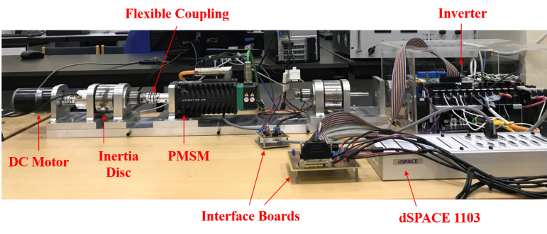 Figure 4: PMSM drive system
In order to observe the voltage increase during regenerative braking, the three-phase line is disconnected from the inverter and the DC-link voltage is maintained only by the DC-bus capacitor. As a result, the voltage begins decreasing. In this period of time, the motor is operating under constant speed. Once the DC-link voltage reaches 300V, the regenerative braking command signal is triggered and the motor operates under braking mode.
4.1. Regenerative braking using speed control mode
Figure 5a shows the reference speed and actual speed of the PMSM before and after regenerative braking is activated. The motor decelerates gradually to zero with a breaking time set to 0.2s. During the regenerative braking period, a negative q-axis current, , is generated by the FOC controller as shown in Figure 5b. The motor mechanical energy is supplied back to the capacitor. Figure 5c shows a negative DC-link current indicating that energy is flowing from the motor to the capacitor. Figure 5d shows that the capacitor voltage is being charged during this period.
 (a) Reference speed and actual speed
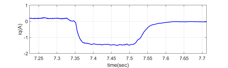 (b) q-axis current
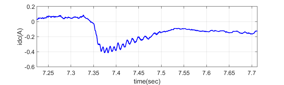 (c) DC-link current
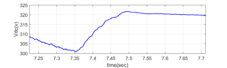 (d) DC-bus voltage
Figure 5: PMSM transient response during regenerative braking under the speed control mode of operation
Table 2 gives a summary of the mode of operation for this form of regenerative braking. The total recovered energy is 70.496 of the motor energy.
Table 2: Summary of the regenerative braking performance for the speed control mode of operation
| (rpm) | Max
(A) |
(V) | Recovery time ( | Recovered Energy
(J) |
Braking Power
(W) |
Max
(A) |
Mech. Energy
(J) |
Efficiency
(%) |
| 21.4 | 0.145 |
Table 3: Summary of the regenerative braking statistics of the torque control mode of operation
| (rpm) | Max
(A) |
(V) | Recovery time ( | Recovered Energy
(J) |
Braking Power
(W) |
Max
(A) |
Mech. Energy
(J) |
Efficiency
(%) |
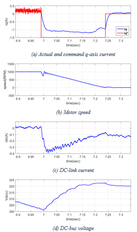 Figure 6: PMSM transient response during regenerative braking under the torque control mode of operation
4.2. Regenerative braking using torque control
Figure 6 shows the motor variables during the torque mode of operation. Initially, the motor speed is regulated by FOC to the desired reference value. Once regenerative braking is initiated, the speed controller is disabled and the motor torque is controlled through the q-axis current. Figure 6a shows the reference current, , and the generated q-axis current, .
The braking time must be tuned in order for the speed to reach zero at the end of the breaking time. Table 3 summarizes the regenerative braking event results under the torque control mode of operation. The results indicate that greater amounts of energy are harvested with the torque control operational mode in comparison to the case of the speed controlled braking.
4.3. Regenerative braking using the Maximum Energy Regeneration switching scheme (MERSS)
To evaluate the PMSM performance with MERSS, the motor is initially powered by the DC-bus capacitor to operate the drive system in driving mode. Next, a break command is activated to operate the system in regenerative braking mode.
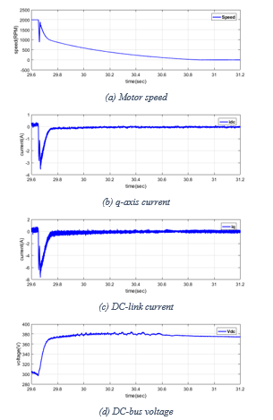 Figure 7: PMSM transient response during regenerative braking under MERSS mode of operation. w0=2000 rpm, d=0.7
As a result, the phase currents reverse their direction and provide energy back to the DC-bus capacitor. The DC-bus voltage increases allowing the DC-bus capacitor to be charged.
Figure 7 shows the transient response of motor speed, q-axis motor current, DC-bus current, and DC-bus voltage. The motor is initially running at constant speed and the DC-bus capacitor is supplying power. When the break command is received, the motor starts decelerating until it comes to rest. The regenerative braking region is a subset of this period where the kinetic energy of the rotor is used to generate electrical energy, and the motor acts as a generator. Figure 8 shows the electric power and energy recovered by the DC-bus capacitor. Following the braking command, energy recovery is activated through the MERSS and the capacitor voltage increases as current is absorbed by the capacitor. Regenerative breaking stops when the motor current reaches the minimum level set by the speed, as given through equation (11).
This process was repeated for different motor speeds and different PWM duty cycles. Varying the duty cycle of the brake command will change the ON-OFF times of the lower inverter switches, as explained previously in Figure 3. Increasing the ON-time period will charge the motor’s inductance for a longer time allowing for the storage of additional energy. This process is similar to the operation of a boost converter. However, if it the ON-period is heavily increased, energy will not be fully recovered due to a short OFF-time period, and will eventually be lost in the switching process. For this reason, the duty cycle must be carefully selected for optimum energy recovery. Figure 9 shows the regenerated power and energy as a function of duty cycle for different motor speeds.
The maximum regenerated energy is compared with the mechanical energy to evaluate the efficiency of the system under MERSS. The energy of the motor and the energy stored in the ultracapacitor during braking are given by:
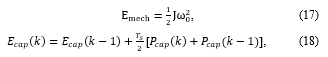 where, is the initial speed of the motor when the braking process starts. Therefore, the efficiency of the braking process takes into consideration the power losses during switching.
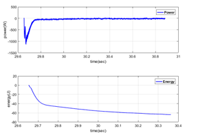 Figure 8: Electric power and energy recovered by the DC bus with MERSS. w0=2000 rpm, d=0.7
Table 4 summarizes the results from this experiment and displays the efficiency, as well as the energy harvested. It can be observed that the optimum duty cycle that yields maximum energy recovery is a function of the speed.
The performance of the MERSS is next compared to FOC by conducting the regenerative braking experiments with FOC under the same operating conditions. Table 5 shows a summary of the results. It can be observed that MERSS yields always a better efficiency than FOC.
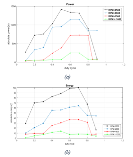 Figure 9: Electric power and energy recovered on the DC bus with MERSS
Table 4: Maximum efficiency of braking at different motor speeds with MERSS.
| (rpm) | Duty Cycle | (%) | ||
| 1000 | 0.5 | 17.27 | 13.84 | 80.14 |
| 1500 | 0.6 | 38.86 | 36.96 | 95.11 |
| 2000 | 0.7 | 69.09 | 64.00 | 92.64 |
| 2500 | 0.7 | 107.95 | 99.74 | 92.40 |
Table 5: Comparative analysis between FOC and MERSS
| w0
(rpm) |
Max
(A) |
(V) | Max
(A) |
Efficiency
(%) |
|||
|
FOC |
1000 | -0.419 | 21.4 | -1.508 | 17.27 | 12.18 | 70.50 |
| 1500 | -1.005 | 54.9 | -2.312 | 38.86 | 27.73 | 71.36 | |
| 2000 | -1.575 | 96.8 | -2.958 | 69.09 | 50.62 | 73.27 | |
|
MERSS |
1000 | -0.2203 | 16.6 | -0.740 | 17.27 | 13.84 | 80.14 |
| 1500 | -2.13 | 52.0 | -4.968 | 38.86 | 36.96 | 95.11 | |
| 2000 | -3.564 | 85.9 | -7.683 | 69.09 | 64.00 | 92.64 |
5. Conclusion
This paper discusses regenerative braking in a PMSM drive system. A new maximum energy recovery switching scheme is developed and compared to FOC. Analysis is carried out on an experimental setup to confirm the effectiveness of regenerative braking under the new scheme. Experimental results show that the maximum current absorbed by the ultracapacitor does not exceed a set limit which is in turn dependent on the ultracapacitor’s voltage, internal resistances of the system and the motor speed. The effect of varying the duty cycle is also studied to uncover the highest efficiency duty cycle for optimum harvesting of regenerated energy.
- K. Yoong, Y. H. Gang, G. D. Gan, C. K. Leong, Z. Y. Phuan, B. K. Cheah, and K. W. Chew, “Studies of regenerative braking in electric vehicle” in 2010 IEEE Conference on Sustainable Utilization and Development in Engineering and Technology (STUDENT), Petaling Jaya, Malaysia, 2010. https://doi.org/10.1109/STUDENT.2010.5686984.
- -Ji Yang, H.-L. Jhou, B.-Y. Ma, and K.-K. Shyu, “A Cost-Effective Method of Electric Brake With Energy Regeneration for Electric Vehicles” Ming-Ji Yang, Hong-Lin Jhou, Bin-Yen Ma, and Kuo-Kai Shyu, Member, IEEE Trans. Ind. Electronics, 56(6), 2203 – 2212, June 2009. https://doi.org/10.1109/TIE.2009.2015356.
- Lu, M. Ouyang, J. Gu, and J. Li, “Instantaneous optimal regenerative braking control for a permanent-magnet synchronous motor in a four-wheel-drive electric vehicle” Proceedings of the Institution of Mechanical Engineers, Part D: Journal of Automobile Engineering, 228(8), 894-908, July 2014. https://doi.org/10.1177/0954407014521173.
- -H. Chen, W.-C. Chi, and M.-Y. Cheng, “Regenerative braking control for light electric vehicles” in IEEE 9th International Conference on Power Electronics and Drive Systems (PEDS), Singapore, 2011. http:// https://doi.org/10.1109/PEDS.2011.6147317.
- Naseri; E. Farjah; T. Ghanbari, “An Efficient Regenerative Braking System Based on Battery/Ultracapacitor for Electric, Hybrid and Plug-In Hybrid Electric Vehicles with BLDC Motor” IEEE Trans. Vehicular Technology, 66(5), 3724–3738, 2017. https://doi.org/10.1109/TVT.2016.2611655.
- Bian, L. Zhu. H. Lan, A, Li. Anhu, and X. Xu, “Regenerative Braking Strategy for Motor Hoist by Ultracapacitor” Chin. J. Mech. Eng., 25(2), 377–384, March 2012. https://doi.org/10.3901/CJME.2012.02.377.
- Zhang, X. Zhang, W. Chen, Y. Rasim, W. Salman, H. Pan, Y. Yuan, and C. Wang, “A high-efficiency energy regenerative shock absorber using supercapacitors for renewable energy applications in range extended electric vehicle” Applied Energy, 178, 177–188, 2016. https://doi.org/10.1016/j.apenergy.2016.06.054.
- Ding, M. Cheng, Chao Hu, Guishu Zhao and Wei Wang, “An energy recovery system of regenerative braking based permanent magnet synchronous motor for electric vehicles” in 2013 International Conference on Electrical Machines and Systems (ICEMS), Busan, South Korea, 2013. https://doi.org/10.1109/ICEMS.2013.6754468.
- Ned Mohan, Advanced Electric Drives: Analysis, Control and Modeling Using Simulink, Wiley 2014.
- Samba Murthy, “Analysis of regenerative braking in electric machines,” MSc Thesis, School of Electrical and Computer Engineering, Georgia Institute of Technology, May 2013.
- Adib and R. Dhaouadi, “Modeling and analysis of a regenerative braking system with a battery-supercapacitor energy storage” in 7th International Conference on Modeling, Simulation, and Applied Optimization (ICMSAO), Sharjah, UAE, 2017. https://doi.org/10.1109/ICMSAO.2017.7934897.
- S. Murthy, D. P. Magee and D. G. Taylor, “Vehicle braking strategies based on regenerative braking boundaries of electric machines” in 2015 IEEE Transportation Electrification Conference and Expo (ITEC), Dearborn, MI, 2015. https://doi.org/10.1109/ITEC.2015.7165809.
- -H. Kim, J.-H. Lee, and C.-Y. Won, “Design and control methods of bidirectional DC-DC converter for the optimal DC link voltage of PMSM drive” Journal of Electrical Engineering and Technology, 9(6), 1944-1953, 2014. http://dx.doi.org/10.5370/JEET.2014.9.6.1944.
- Jiaqun and C. Haotian, “Regenerative brake of brushless DC motor for light electric vehicle” in 2015 18th International Conference on Electrical Machines and Systems (ICEMS), Pattaya, Thailand, 2015. https://doi.org/10.1109/ICEMS.2015.7385262.