WordPress database error: [User 'astesjco_WP0QT' has exceeded the 'max_questions' resource (current value: 1)]SELECT wp_posts.* FROM wp_posts WHERE ID IN (41514,41515,41516,41517,41518,41519,41520,41521,41522,41523,41524,41525,41526,41527,41528,41529,41530,41531,41532,41533,41534,41535,41536,41537)
WordPress database error: [User 'astesjco_WP0QT' has exceeded the 'max_questions' resource (current value: 1)]SELECT post_id, meta_key, meta_value FROM wp_postmeta WHERE post_id IN (41514,41515,41516,41517,41518,41519,41520,41521,41522,41523,41524,41525,41526,41527,41528,41529,41530,41531,41532,41533,41534,41535,41536,41537) ORDER BY meta_id ASC
Fuzzy Logic Based Selective Harmonic Elimination for Single Phase Inverters

Adv. Sci. Technol. Eng. Syst. J. 3(3), 161–167 (2018);
 DOI: 10.25046/aj030322
A selective harmonic elimination system using fuzzy logic for the elimination of high magnitude harmonics with frequencies close to fundamental in the output voltage of single phase inverters is presented. The system does not require look up tables for storage of the data as in traditional harmonic elimination methods. The input of the fuzzy system is the modulation index values. The output of the fuzzy system provides the switching angles which are further used to construct the switching signal for the switches in the inverter. With this fuzzy logic based selective harmonic elimination system, predetermined dominant low rank harmonics are successfully eliminated. Simulations are made with Matlab/Simulink and the results are presented which show the effectiveness of the presented harmonic elimination system.
1. Introduction
This paper is an extension of work originally presented in 2017 XXVI International Scientific Conference Electronics (ET) [1]. The use of power electronic devices in industrial and consumer applications has resulted nonlinear sinusoidal voltage and current to be drawn from the source. These nonlinear loads distort the sinusoidal form of the alternating current which results harmonics in the electrical system. The power quality of an electrical system is determined by its harmonic content. These harmonics may be classified as voltage or current harmonics. These harmonics can occur either supply or load. Current harmonics are generated by the harmonics of the source voltage which are depend on the type of the load connected to supply which can be resistive, inductive or capacitive. Nonlinear operation of power converters feeding loads cause harmonics to be produced in the load. These harmonics cause extra heating in transformers and motors.
Supply harmonics are produced by the source with nonsinusoidal voltage or current waveforms. Supply harmonics produce extra loss, cause electromagnetic interference and ripple torques in ac motors [2].
A pulse width modulated inverter which converts dc source to ac supply with desired voltage and frequency is used in many electrical devices such as uninterruptable power supplies (ups), switch mode power supplies(smps), machine drives. However, it is seen that the output voltage of the inverters has higher harmonic content.
Among others [3-4], the pulse width modulation (pwm) technique is one of the commonly applied modulation strategy which controls the amplitude and frequency of the voltage produced by inverters.
Pwm techniques have been widely used in converter and inverter control where the switches are switched on and off number of times in each period. The controlled output signal is obtained by changing the width of these pulses.
Different pwm methods have been developed to suppress harmonics in converters and inverters. These techniques can be summarized as
- Carrieer based pwm
- Space vector pwm
- Third harmonic injection pwm
- Selective harmonic elimination pwm
One of the effective pwm method for the suppression of harmonics from the spectrum of the inverter output voltage is the selective harmonic elimination (SHE) technique [5-7].
The voltage or current waveform is represented by Fourier series expansion in SHE technique. The coefficients of the harmonics those will be eliminated are set to zero and the coefficient of the fundamental is set to the desired value. Hence, a set of nonlinear equation is obtained. This equation set need to be solved in terms of unknown switching angles for each value of modulation index. The number of equation depends on the number of harmonics to be eliminated [1].
For the offline approach the nonlinear equation set is solved for every modulation index values and stored in look up tables. These modulation index values used in the microcomputer for generating switching instants. A huge number of tables of data are required to be saved which also require large memory. This problem can be avoided by online approach. Therefore, intelligent methods are proposed for the SHE.
In this study, a fuzzy logic (FL) based SHE is presented. FL is used to obtain switching moments for the switching elements in the single-phase inverter.
The main contribution using FL is the fast response in real time operation constructing the pwm patterns for improving the inverter output voltage waveform. Whereas, in conventional methods the calculations of the switching instants are made off line. The controller needs a look up table to store the switching instants for SHE.
2. Selective Harmonic Elimination
SHE is a modulation method aiming to obtain the appropriate switching instants to suppress the low order harmonics. In SHE the switching moments are determined by using the desired magnitude of the fundamental and harmonics to be suppressed. Main aim is to determine switching angles so that the fundamental component is at the desired value and undesired harmonics which are the lower order harmonics are eliminated. Thus, Total Harmonic Distortion (THD) of the output voltage is also minimized.
Figure 1 Shows a single phase full bridge inverter structure. In conventional pwm inverters the gate signals for the switching elements in the first leg are produced by comparing a sinusoidal modulation signal with a triangular carrier wave.
180° phase shifted signals of the first leg are applied to the second leg of the inverter. Thus, the gate signals for the switches S1, S4 and S2, S3 are synchronized.
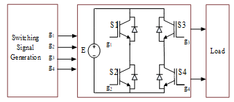 Figure 1. Single-phase symmetric pwm inverter
The technique used to eliminate or minimize low rank harmonics while keeping the magnitude of the fundamental component at desired value by appropriately choosing the switching angles of the voltage waveform of an inverter is known as the SHE [8-11]. With this technique, the magnitude of the fundamental component and the harmonics to be eliminated are determined and the corresponding switching angles are calculated.
The output voltage waveshape may be either bipolar or unipolar as in Figure 2 which shows normalized output voltage waveforms. In bipolar waveform, the output voltage is two level in which both +E and –E voltage pulses are used in each half period. In unipolar waveform, the output voltage is three level and only one of +E or –E voltage pulses are used in each half period. The output voltage waveshape of the SHE modulated inverter is constructed to have a quarter wave symmetry.
The two switches are not turned on or off in the same inverter leg at the same time. They are operated in a complementary manner that is, one switch turned on and other turned off in the same inverter leg. Thus, inverter need only two switching signals for the gate of upper switches which are produced by comparing a sinusoidal modulating wave and triangular carrier wave.
In the unipolar modulation two sinusoidal modulating wave with same magnitude but 180° out of phase are used. Switching signals for the gates of upper switches in the inverter legs are produced by comparing these two modulating waves with a sawtooth carrier.
The unipolar voltage waveform contains three states as presented in Figure 3. Signal pulses are generated with switching instants (α1, α2, α3,…, αN).
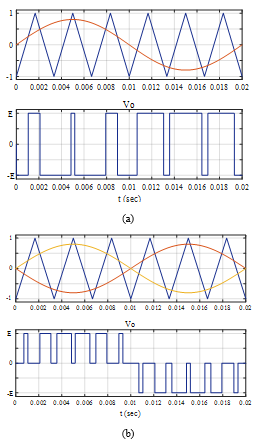 Figure 2. Bipolar and unipolar waveforms
Periodic signals can be constructed from a sum of sine and cosine functions. by a fundamental and a set of harmonic components. The coefficients of these functions can be obtained by applying Fourier transformation. Thus, the Fourier representation of the inverter output voltage is;
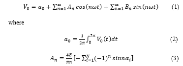 Due to odd and quarter wave symmetry, even harmonics do not exist in the output voltage waveform and Fourier coefficients An and a0 are equal to zero [12].
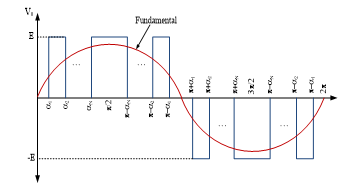 Figure 3. Inverter output voltage
Only the odd harmonics with sine components exist in the output voltage, thus (1) can be written as:
![]() where Bn is the amplitude of the nth harmonic voltage and is given by
where Bn is the amplitude of the nth harmonic voltage and is given by
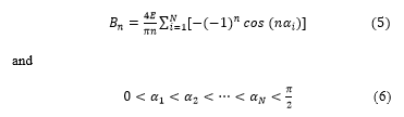 E is the dc bus voltage, w=2pf1, f1 is the frequency of the fundamental component and N is the number of switching angles per quarter cycle.
The goal of the SHE method is to determine the switching angles α1, α2,…,αN in the inverter output voltage so that the amplitudes of the harmonic components B3, B5,…,BN-1 are zero and the fundamental component B1 equal to the desired amplitude.
Applying the constraints defined above and using (5), the following equation set can be obtained
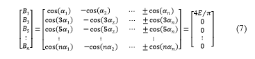 where n=1, 3, 5… N and N is the number of pulse in every quarter cycle.
The first equation in this equation set is used to adjust the amplitude of the fundamental and the others are used for the suppression of harmonics.
Thus, N-1 harmonics can be eliminated by calculating N switching angles [13, 14].
If the amplitude of the fundamental component B1 need to be adjusted then
![]() where m is the modulation index which is the ratio of fundamental to the maximum obtainable fundamental.
where m is the modulation index which is the ratio of fundamental to the maximum obtainable fundamental.
The set of nonlinear equations in (7) need to be solved using numerical methods [15, 16] to obtain the switching instants.
In this study, Newton-Raphson (NR) method, as in [17, 18] which is developed for the solution of nonlinear equations is used to solve the nonlinear equation set given in (7). The switching angles are obtained by a program developed in Matlab for solving the nonlinear algebraic transcendental equations. Solution obtained from NR is used to setup the input/output membership functions in the fuzzy controller. Table 1 lists the angles for different m values for 10 harmonics to be eliminated.
Table 1. Switching angles corresponding to modulation index
| m | 0.1 | 0.2 | 0.4 | 0.6 | 0.8 | 1 |
| a1 | 14.793 | 14.578 | 14.109 | 13.587 | 12.997 | 12.093 |
| a2 | 15.181 | 15.352 | 15.636 | 15.821 | 15.854 | 15.296 |
| a3 | 29.607 | 29.195 | 28.298 | 27.295 | 26.138 | 24.287 |
| a4 | 30.357 | 30.691 | 31.261 | 31.655 | 31.749 | 30.556 |
| a5 | 44.450 | 43.876 | 42.633 | 41.232 | 39.571 | 36.681 |
| a6 | 45.511 | 45.996 | 46.853 | 47.500 | 47.732 | 45.735 |
| a7 | 59.335 | 58.645 | 57.170 | 55.509 | 53.478 | 49.375 |
| a8 | 60.635 | 61.246 | 62.379 | 63.337 | 63.881 | 60.767 |
| a9 | 74.268 | 73.518 | 71.947 | 70.215 | 68.082 | 62.457 |
| a10 | 75.718 | 76.422 | 77.791 | 79.092 | 80.213 | 75.560 |
| a11 | 89.249 | 88.495 | 86.967 | 85.372 | 83.569 | 75.996 |
3. Fuzzy Logic Controller
FL is a theory used to represent uncertain information. It is first formulated by Lotfi Zadeh in 1960s [19]. FL is a crisp model of a system. It uses rule base to convert crisp inputs to corresponding crisp output values. This technique has been successful especially when rules cannot be perfectly known and can be used in situations where the device cannot be described by mathematical models. Decision making capability of fuzzy logic controller (FLC) is achieved by human behavior.
Fuzzy systems provide a quick and approximate solution for complex systems which do not have exact mathematical model [20]. The real life and industrial applications of FL can be found in [21-23].
FL is realized in four steps which are the determination of fuzzy sets, definition of membership functions, construction of rules and defuzzification as shown in Figure 4.
Fuzzification is the first step in FL system. In this step, crisp input values are measured and converted to suitable linguistic variables using expert’s knowledge and experience.
The second step is the development of rule data base which defines the principles of the controller in terms of the relationship between input and output. This step is known as Inference Engine and supplies the required information for control rules
The last step is the conversion of the fuzzy outputs to control action which is called as Defuzzification which provides an actual control action.
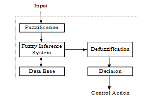 Figure 4. Block diagram of the FL system
Two types of fuzzy inference system which are Mamdami-type and Sugeno-type can be used. These types are differ according to the determination of outputs. Sugeno-type inference produces an output that is either constant or linear mathematical expression.
Due to the use of numerical values at the input and outputs, Sugeno-type fuzzy system is used for the implementation of the input and output data. Figure 5 shows the input membership function.
The outputs of the fuzzy control system which are the switching angles are computed for a given input which is the modulation index as shown in Figure 6.
The input data are represented by 10 membership functions. Because 10 harmonics are going to be eliminated which requires 11 switching angle thus 11 outputs each has 50 constant type membership functions for the representation of output data are used in the fuzzy system. Totally 104 rules are used between the input membership functions and output membership functions.
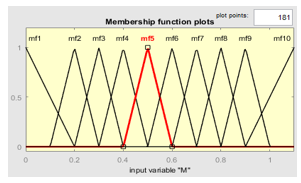 Figure 5. Input membership function
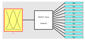 Figure 6. Fuzzy system
4. Switching Signal Generation
The switching instants corresponding to each m are determined by solving the nonlinear equation set for every value of m. These m and switching angles values are used in FLC. The m is used as the input to FLC and the output of this controller is the corresponding switching angles.
The switching instants obtained from FLC for a given m value are used as inputs for generation of switching signals.
As in traditional pwm methods, the switching angles produced by FL are compared with a timer content with specified frequency to produce pwm switching signals.
Figure 7 shows the generation of the switching signals for elimination of three harmonics i.e. N=4. In this system the switching angles are a1=23.56º, a2=39.26º, a3=48.96º and a4=89.20º. If the frequency is 50 Hz, the switching signals are obtained by comparing the timer content which is the triangular wave with the switching angles. Because of the symmetry, only the half period is given in this figure.
The Simulink block used to obtain the switching signals is shown in Figure 8.
The signals are constructed by comparison of switching instants with the sawtooth carrier and given to inverter switches as in Figure 9. Figure 10 represents a switching signals generation of 3 harmonic elimination.
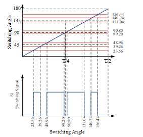 Figure 7. Switching signal generation for elimination of three harmonics
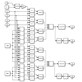 Figure 8. Simulink block for switching signal generation for the elimination of three harmonics
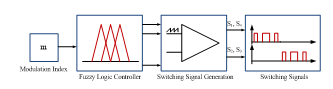 Figure 9. Switching signals generation
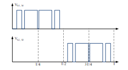 Figure 10. Sample switching signals for N=4
5. Simulation Results
To present the effectiveness of FL based SHE, a model of the system is implemented for the simulations using Matlab/Simulink.
The Simulink block is given in Figure 11 where the aim is to eliminate 10 voltage harmonics (3, 5, 7, 9, 11, 13, 15, 17, 19, 21). The switching angles and the corresponding switching times for N=11 and m=0.9 are given in Table 2.
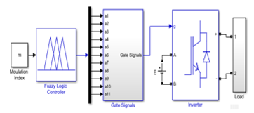 Figure 11. Simulink block of FL based SHE
Table 2. Switching angles (deg) and switching instants (ms) for n=11 and m=0.9
| a1 | a2 | a3 | a4 | a5 | a6 | a7 | a8 | a9 | a10 | a11 |
| 12.62 | 15.71 | 25.38 | 31.44 | 38.41 | 47.25 | 51.91 | 63.25 | 66.15 | 79.78 | 81.66 |
| t1 | t2 | t3 | t4 | t5 | t6 | t7 | t8 | t9 | t10 | t11 |
| 0.70 | 0.87 | 1.41 | 1.74 | 2.13 | 2.62 | 2.88 | 3.51 | 3.67 | 4.43 | 4.53 |
For better visualization, a period of the waveform is shown in Figure 12 where horizontal axis is converted to degrees.
Figure 13 shows the inverter output voltage and filtered current waveform when N=11 and m=0.9.
The spectrum of the voltage is presented in Figure 14. The harmonics 3, 5, 7, 9, 11, 13, 15, 17, 19, 21 are all eliminated from this spectrum.
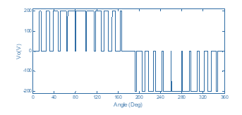 Figure 12. One period of inverter output voltage
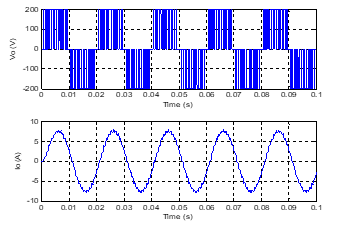 Figure 13. Inverter output voltage and current
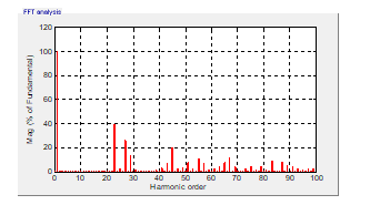 Figure 14. Inverter output voltage and its spectrum
A change in m from 0.8 to 1 is applied at time t=0.1s and the voltage waveform obtained is presented in Figure 15. The output voltage spectra are given in Figure 16 and Figure 17 for the cases m=0.8 and m=1 respectively. Figure 18 is given to clearly see the effect of this change in the voltage waveform. 10 low rank harmonics are eliminated from the spectra.
To show the effectiveness of the presented FL based harmonic elimination system, the first fifteen harmonics which are 3, 5, 7, 9, 11, 13, 15, 17, 19, 21,23, 25, 27, 29, and 31st harmonics are taken to be eliminated. The output voltage waveform and its spectrum are given in Figure 19 and Figure 20. It is clearly seen that 15 predefined harmonics are eliminated.
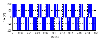 Figure 15. Zoomed output voltage waveform when m changes from 0.8 to 1 at t=0.1
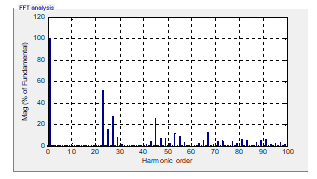 Figure 16. Inverter output voltage and its spectrum for m=0.8 (t<0.1)
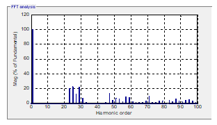 Figure 17. Inverter output voltage and its spectrum for m=1 (t>0.1)
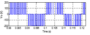 Figure 18. Zoomed inverter output voltage
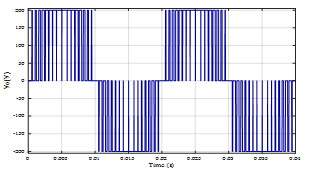 Figure 19. Inverter output voltage waveform with elimination of 15 harmonics
The total harmonic distortion was also examined with the FL based SHE method. THD values are 18.52% and 13.71% for the elimination of 10 harmonics and 15 harmonics. The same load is used in both situations. By using this technique THD is also reduced.
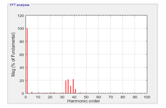 Figure 20. Inverter output voltage spectrum with elimination of 15 harmonics
6. Conclusion
The output voltage of inverters is nonsinusoidal because of the nonlinear switching characteristics of the switches. This voltage contains harmonics with high magnitude with frequencies near fundamental. Distorted voltage used in electronic equipment may reduce the power quality and cause defects. Thus the output voltage waveform of inverters need to be improved. In this study, a FL based SHE for single phase inverters is presented. FL system is used for the computation of switching angles using modulation index. The switching signals are generated for the switches of the inverter using the output of the fuzzy system.
Matlab/Simuink programming environment is used to implement the presented SHE for single phase pwm inverter. Various modulation indices are used for the simulations. Some results are given to show the effectiveness of the technique. The simulation results verified the elimination of the selected harmonics from the frequency spectrum of the voltage waveform. Total harmonic distortion is also reduced by using the presented technique.
- Z. B. Duranay, H. Guldemir, “Fuzzy Logic Based Harmonic Elimination in Single Phase Inverters” in XXVI International Scientific Conference Electronics, Sozopol Bulgaria, 2017. https://doi.org/10.1109/ET.2017.8124342
- O. Bouhali, M. Berkouk, B. Francois, C. Saudemont, S. Labiod, “Solving harmonics elimination problem in three-phase voltage controlled inverter using artificial neural networks” Journal of Electrical Systems, 1(1), 39-51, 2005.
- M. H. Rashid, Power Electronics Handbook: Devices, Circuits and Applications, Academic Press, 2010.
- N. Mohan, T. M. Undeland, W. P. Robbins, Power Electronics: Converters, Applications and Design, John Wiley & Sons Inc., 1995.
- E. Hendawi, “Single phase inverter with selective harmonics elimination pwm based on secant method” Int. Journal of Engineering Inventions, 4(12), 38-44, 2015.
- M. I. Jahmeerbacus, M. Sunassee, “Evaluation of Selective Harmonic Elimination and Sinusoidal PWM for Single-Phase Dc to Ac Inverters Under Dead-Time Distortion” in 23rd International Symposium on Industrial Electronics, Istanbul Turkey , 2014. https://doi.org/10.1109/ISIE.2014.6864658
- B. M. Saied, Q. M. Alias, A. S. AL-soufy, “Intelligent systems based selective harmonic elimination (she) for single phase voltage sourse inverter” Al Rafdain Enginering Journal, 16(3), 71-81, 2008.
- P. N. Enjeti, P. D. Ziogas, J. F. Lindsay, “Programmed pwm techniques to eliminate harmonics: a critical evaluation” IEEE Trans. Ind. Appl., 26(2), 302-316, 1990. https://doi.org/10.1109/28.54257
- M. S. A. Dahidah, V. G. Agelidis, “Non-symmetrical Selective Harmonic Elimination PWM Techniques: The Unipolar Waveform” in 38th IEEE Power Electronics Specialists Conference, Orlando FL USA, 2007. https://doi.org/10.1109/PESC.2007.4342290
- H. S. Patel, R. G. Hoft, “Generalized techniques of harmonic elimination and voltage control in thyristor inverters: part I harmonic elimination” IEEE Trans. Ind. Appl., IA-9(3), 310-317, 1973. https://doi.org/10.1109/TIA.1973.349908
- S. Tuncer, Y. Tatar, H. Guldemir, “A shepwm technique with constant v/f for multilevel inverters” Journal of Polytechnic, 8(2), 123-130, 2005.
- J. N. Chiasson, M. Tolbert, K. J. McKenzie, Z. Du, “A complete solution to the harmonic elimination problem” IEEE Trans. Power Electron., 19(2), 491-499, 2004. https://doi.org/10.1109/TPEL.2003.823207
- V. G. Agelidis, A. I. Balouktsis, M. S. A. Dahidah, “A five-level symmetrically defined selective harmonic elimination pwm strategy: analysis and experimental validation” IEEE Trans. Power Electron., 23(1), 19–26, 2008. https://doi.org/10.1109/TPEL.2007.911770
- F. G. Turnbull, “Selected harmonic reduction in static dc-ac inverters” IEEE Trans. Comm. Electron., CE-83(73), 374-378, 1964. https://doi.org/10.1109/TCOME.1964.6541241
- D. Czarkowski, D. V. Chudnovsky, G. V. Chudnovsky, I. W. Selesnick, “Solving the optimal pwm problem for single-phase inverters” IEEE Trans. Circuits-I, 49(4) , 465-475, 2002. https://doi.org/10.1109/81.995661
- J. Sun, I. Grotstollen, “Pulse Width Modulation Based on Real-Time Solution of Algebraic Harmonic Elimination Equations, Industrial Electronics” in 20th International Conference on Control and Instrumentation, Bologna Italy, 1994. https://doi.org/10.1109/IECON.1994.397753
- G. Carrara, S. Gardella, M. Marchesoni, R. Salutari, G. Sciutto, “A new multilevel pwm method: a theoretical analysis” IEEE Trans. Power Electron., 7(3), 497–505, 1992. https://doi.org/10.1109/63.145137
- D. Ahmadi, K. Zou, C. Li, Y. Huang, J. Wang, “A universal selective harmonic elimination method for high-power inverters” IEEE Trans. Power Electron., 26(10), 2743–2752, 2011. https://doi.org/10.1109/TPEL.2011.2116042
- L. A. Zadeh, “Fuzzy sets” Information and Control, 8, 338-353, 1965. https://doi.org/10.1016/S0019-9958(65)90241-X
- A. Kaur, A. Kaur, “Comparison of Mamdani-Type and Sugeno-Type fuzzy inference systems for air conditioning system” Int. J. of Soft Comp. and Eng., 2(2), 323-325, 2012.
- H. Singh, M. M. Gupta, T. Meitzler, et al. “Real-life applications of fuzzy logic” Advances in Fuzzy Systems, 2013, 1-3, 2013. http://dx.doi.org/10.1155/2013/581879.
- P. M. Larsen. “Industrial application of fuzzy logic control” International Journal of Man-Machine Studies. 12(1), 3-10, 1980. https://doi.org/10.1016/S0020-7373(80)80050-2.
- R. R.Yager, and L. A. Zadeh. “An introduction to fuzzy logic applications in intelligent systems”. Vol. 165. Springer Science & Business Media, 2012.
WordPress database error: [User 'astesjco_WP0QT' has exceeded the 'max_questions' resource (current value: 1)]SELECT * FROM wp_ayschart_charts WHERE id = '1034'
WordPress database error: [User 'astesjco_WP0QT' has exceeded the 'max_questions' resource (current value: 1)]SELECT option_name, option_value FROM wp_options WHERE option_name IN ('_transient_astesj_rel_d65018d3ae10005e522eb053000d8309','_transient_timeout_astesj_rel_d65018d3ae10005e522eb053000d8309')
WordPress database error: [User 'astesjco_WP0QT' has exceeded the 'max_questions' resource (current value: 1)]SELECT wp_posts.ID
FROM wp_posts INNER JOIN wp_postmeta ON ( wp_posts.ID = wp_postmeta.post_id )
WHERE 1=1 AND wp_posts.ID NOT IN (4256) AND (
( wp_postmeta.meta_key = 'citation_keywords' AND wp_postmeta.meta_value LIKE '%Fuzzy logic%' )
OR
( wp_postmeta.meta_key = 'citation_keywords' AND wp_postmeta.meta_value LIKE '%Harmonic analysis%' )
OR
( wp_postmeta.meta_key = 'citation_keywords' AND wp_postmeta.meta_value LIKE '%Harmonic elimination%' )
OR
( wp_postmeta.meta_key = 'citation_keywords' AND wp_postmeta.meta_value LIKE '%Inverter%' )
OR
( wp_postmeta.meta_key = 'citation_keywords' AND wp_postmeta.meta_value LIKE '%Pulse width modulation%' )
) AND wp_posts.post_type IN ('elementor-hf', 'elementor_library', 'page', 'post', 'sdm_downloads', 'wpb_gutenberg_param') AND ((wp_posts.post_status = 'publish'))
GROUP BY wp_posts.ID
ORDER BY wp_posts.post_date DESC
LIMIT 0, 100
WordPress database error: [User 'astesjco_WP0QT' has exceeded the 'max_questions' resource (current value: 1)]INSERT INTO `wp_options` (`option_name`, `option_value`, `autoload`) VALUES ('_transient_timeout_astesj_rel_d65018d3ae10005e522eb053000d8309', '1784973682', 'off') ON DUPLICATE KEY UPDATE `option_name` = VALUES(`option_name`), `option_value` = VALUES(`option_value`), `autoload` = VALUES(`autoload`)
WordPress database error: [User 'astesjco_WP0QT' has exceeded the 'max_questions' resource (current value: 1)]INSERT INTO `wp_options` (`option_name`, `option_value`, `autoload`) VALUES ('_transient_astesj_rel_d65018d3ae10005e522eb053000d8309', '<p>No related articles were found.</p>', 'off') ON DUPLICATE KEY UPDATE `option_name` = VALUES(`option_name`), `option_value` = VALUES(`option_value`), `autoload` = VALUES(`autoload`)
No related articles were found.