Complete Modeling of the Hydrogen Stored in a Spherical Cavity

Adv. Sci. Technol. Eng. Syst. J. 3(4), 122–129 (2018);
 DOI: 10.25046/aj030413
Hydrogen is the lightest of gases and possesses the lowest density. However at ambient temperature and pressure it occupies a large volume. This necessitates compressing it at high pressures up to 800 Bars to minimize the volume. The immense interest generated by hydrogen comes from the fact that it has the best energy per weight ratio of all fuels and the ecological nature of the combustion product. From the pedagogical point of view, it is also the most taught and involved in research, in particular in quantum mechanics. This aspect is treated in this article in order to solve the problem of storage of the hydrogen by minimizing losses. The solutions envisaged are, first, the improvement of the theory to understand the physical phenomena that occur in the physical system, especially the resolution of the transcendental equation, and then the means of perfecting the materials constituting the cavity. Quantum scale investigations began with solving the Schrodinger equation at three-dimensional spherical symmetry, taking into account the boundary conditions of Victor Gustave Robin on the inner walls of the envelope. The clean energies that are stored in a spherical-shaped cavity have been modeled theoretically by solving the transcendental equation. The last part of the article is devoted to the thermodynamic properties of the hydrogen gas, particularly the dependence of the energy with the pressure and the temperature.
1. Introduction
At all times, energy has been indispensable for maintaining the life of living beings on our planet earth. It first appeared as fossil energy in the form of coal, which originated from the rapid burial of trees and plant debris within some sedimentary basins. This fossil energy remained for a long time in the primitive state until the 19th century era of running in search of black gold. Fossil fuels then include coal, oil and gas and are essential for transport, power generation, heating, plant operation and others.
Through many scientific meetings on renewable energies, the discusses in current research focuses on hydrogen as an energy carrier. This implies that, in order to control this renewable energy, four levels of interventions have to be considered simultaneously, along a complete path leading to its proper use and management.
– The production or source of energy.
– The transportation.
– The storage.
– The distribution.
The origin of the vector being the source of artificial production since hydrogen does not exist in the natural state and must be extracted by reforming from hydrocarbons or by hydrolysis from water, and the arrival tip is the distribution to the consumers.
This article is devoted to the storage of hydrogen, with two major difficulties to be answered: the safety and the miniaturization of the storage tanks because hydrogen is an explosive product and little dense which implies that it occupies a large volume even in small quantity. The density of hydrogen at the temperature T = 273 K and the pressure P = 1 atm is d = 0.0899 g/L equivalent to 8.99.10-5 g/cm3 [1]. Numerous storage means have been envisaged for hydrogen and are currently competing: gas storage under pressure, cryogenic storage in liquid form, solid storage in hydrides and adsorbent materials [2].
2. The gas storage
The innovative solution for pressure storage today comes from wound fiber and resin structures that provide much higher storage pressures while reducing envelope mass. At present, operating pressures of 350 bars are commonly proposed and the research is directed towards even greater pressures in the order of 700 to 800 bars [3]. The structure of a composite fiber and resin tank is more complex than that of a steel tank. At least three envelopes are used which each fulfill a different function.
The internal envelope, made of aluminum, does not contribute to the mechanical strength of the tank but must; however, withstand the high stresses induced by the load variations during the filling and use cycles. To replace aluminum, some research is directed towards polymeric materials such as high density polyethylene. These materials are even lighter than metal, stress resistant, easy to work with and inexpensive but they still suffer from the fact that they are significantly more permeable to hydrogen than aluminum.
The middle envelope ensures the mechanical strength of the tank it is the working structure. It is obtained by winding a continuous network of carbon or glass fibers coated with a thermosetting or thermoplastic resin directly on the internal envelope. This winding is affected by rotating the inner envelope and by scanning the fibers in and out at a given angle up to the total overlap. It is thus possible to produce a composite structure of several covering layers with different angles. A firing phase then allows the polymerization of the resin and finishes the production phase.
The outer casing acts as a protector against external aggressions such as moisture, shocks or friction, which can cause the carbon or glass fiber to become brittle and the tank to become brittle locally. This envelope is most often made of cheap fiberglass and can be completed with a foam thickness.
Finally, pressure storage must be evaluated according to the risks of use, particularly in the case of on-board tanks. This involves a series of homologation tests involving the validation of the storage system for various accidental scenarios such as gas leakage, crash, fire, impact, as well as corrosion resistance and behavior in cycling and fatigue.
3. Mathematical theory
To solve theoretically, hydrogen gas transmission phenomenon that is enclosed in a spherical cavity under high pressure, two equations are necessary: the Schrödinger equation (1), which is well known with the Hamiltonian and the energy , and the Victor Gustave Robin boundary condition (2),
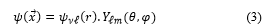
![]() The self-adjoint extension parameter takes into account the constituent material of the cavity, is the wave function, ∂Ω is the limit of a spatial region Ω and is the unit vector perpendicular to the surface. As usual, the wave function can be factored as the product of a radial function with a spherical harmonic function according to the following expression
The self-adjoint extension parameter takes into account the constituent material of the cavity, is the wave function, ∂Ω is the limit of a spatial region Ω and is the unit vector perpendicular to the surface. As usual, the wave function can be factored as the product of a radial function with a spherical harmonic function according to the following expression
 3.1. The transcendental equation of the energy spectrum
When replacing (3) in (2) and for a spherical cavity, the most general perfectly reflecting boundary condition of (2) takes the form
![]() The Hamiltonian radial equation of the hydrogen atom, in spherical coordinates, takes the expression:
The Hamiltonian radial equation of the hydrogen atom, in spherical coordinates, takes the expression:
![]() In this case, the parameterized energy is as [4]
In this case, the parameterized energy is as [4]
![]() While in the infinite volume the quantum number ν takes integer values for the bound state spectrum, in the cavity ν is in general real-valued. Introducing the Bohr radius
While in the infinite volume the quantum number ν takes integer values for the bound state spectrum, in the cavity ν is in general real-valued. Introducing the Bohr radius
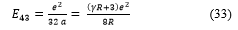
![]() The energy with function of the Bohr radius is
The energy with function of the Bohr radius is
![]() and the normalizable wave function is given by
and the normalizable wave function is given by
![]() where is an associated Laguerre function, a is the Bohr radius and A is a constant.
where is an associated Laguerre function, a is the Bohr radius and A is a constant.
When resolving (4), the energy spectrum is then determined by the transcendental equation [4]
 3.2. Resolution of the transcendental equation
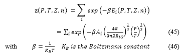
Hydrogen energies are quantified by the two parameters ν and , these energies depends on the self-adjoint extension parameter (as possible) which identify the materiel properties of the inner cavity wall, many scientists consider the cavity envelopes made with nanotechnology, fibers and polymers, [5-13]. The energies of the hydrogen are also a function of the radius of the spherical cavity.
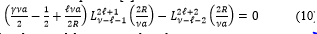
Consider the case , (10) takes the form
![]() For , (11) becomes
For , (11) becomes
![]() replacing the expressions of the generalized Laguerre polynomials and
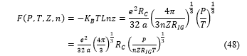
replacing the expressions of the generalized Laguerre polynomials and
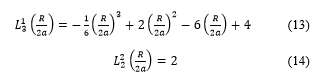 Doing calculations, one can arrive to (15)
 Equation (15) is a polynomial equation of degree three, with using the informatics processing, the solutions are found using the roots Matlab procedure, there is three distinct values for , then from (16), three values for the cavity radius are deduced. The solutions are reported in the Table 1
Table 1: values of , and corresponding values for the radius ? calculated.
| X=R/2a | R(x10-10 meter) |
| 7.7588 | 8.2116 |
| 3.3054 | 3.4983 |
| 0.9358 | 9.9041 |
In this case, the quantify parameter of the energies is always equal to four ( ), and the azimuthally parameter is changed equal to one ( ), (11) becomes
![]() replacing the expressions of the generalized Laguerre polynomials and
replacing the expressions of the generalized Laguerre polynomials and
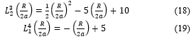 Then, taking into account (18) and (19), (17) becomes
![]() After calculations (20) takes the form
After calculations (20) takes the form
![]() Where is the new variable, which is defined by the (16), and is real number parameter defined as
Where is the new variable, which is defined by the (16), and is real number parameter defined as
![]() This is a third order equation. To find the solutions use the graphic informatics processing, with resolving the system
This is a third order equation. To find the solutions use the graphic informatics processing, with resolving the system
![]() The calculations were done with five different values of the parameter . For each curve it exist two positive solutions, the results are written in the Table 2
The calculations were done with five different values of the parameter . For each curve it exist two positive solutions, the results are written in the Table 2
In this case, the energy corresponding to when and , is stationary and stay constant along all the abscises axes.
As well as the section before, the quantify parameter of the energies is always equal to four ( ), and the azimuthally parameter is change equal to two ( ), (11) becomes
![]() Table 2: The solution points of (21)
Table 2: The solution points of (21)
|
m |
X= R/2a |
R=2aX (x10-10 meter) |
E=e2X/(16R) (x10-30Joule) |
| First points | |||
| 11 | 2.5876 | 2.7386 | 15.118 |
| 19 | 2.6604 | 2.8157 | 15.118 |
| 27 | 2.6907 | 2.8477 | 15.118 |
| 35 | 2.7073 | 2.8653 | 15.118 |
| 43 | 2.7177 | 2.8763 | 15.118 |
| Second points | |||
| 11 | 7.0658 | 7.4782 | 15.118 |
| 19 | 7.1347 | 7.5511 | 15.118 |
| 27 | 7.1639 | 7.5820 | 15.118 |
| 35 | 7.1801 | 7.5991 | 15.118 |
| 43 | 7.1903 | 7.6099 | 15.118 |
The graphic resolution is reported in the Figure 1
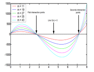 Figure 1: Graphic resolution of (23), showing the curves G(X) and the two solution points.
replacing the expressions of the generalized Laguerre polynomials and
 Doing calculations, one can arrive to the equation below
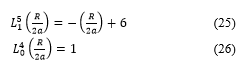
![]() the variable and the parameter are defined by respectively (16) and (22). Solutions can be found graphically from the curve with resolving the equality
the variable and the parameter are defined by respectively (16) and (22). Solutions can be found graphically from the curve with resolving the equality
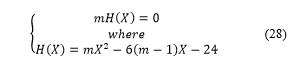 It exists only one positive solution, the unique value for and the radius are obtained when the parameter is fixed equal to , with one great value of the self-adjoint extension parameter ( ), this maximizes the hydrogen energy storage. The result is reported in Table 3
Table 3: value of the radius R.
| m (x1030) | X= R/2a | R(x10-10 meter) |
| 2.1167 | 6.0000 | 6.3502 |
The graphic resolution is reported in the Figure 2
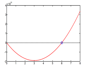 Figure 2: Graphic resolution of (28), showing the red curve H(X) for and the unique solution (blue point).
Consider here the quantify parameter of the energies equal to four ( ), and the azimuthally parameter is change equal to three ( ), (11) becomes
 Resolving (31), the Bohr radius, a, depend on the cavity radius according to the form
![]() And, by (8) and (32), the energy is
And, by (8) and (32), the energy is
 4. Graphics processing of the energies
The informatics processing of the hydrogen energies is made in the Matlab R2009a environment. All the expressions of the energies decrease with the cavity radius R in the function form
![]() except the last energy .
except the last energy .
4.1. Hydrogen energies graphics
It exists three possible energies corresponding, respectively to three different radius of the spherical tank storing the hydrogen. These values are reported in the Table 4.
Table 4: values of the cavity radius and their corresponding energies
| R (x10-10 meter) | E40=e2X/(16R) (x10-30 Joule) |
| 0.9904 | 125.30 |
| 3.4982 | 035.50 |
| 8.2114 | 015.10 |
The Figure 3 shows the behavior of the energy with function of the radius , it decreases like the function . The three solution points of the radius are fixed in the curve. One can remark that the radius axes coordinates are very small, atomic scale, because there is no correlation between the energy and the self-adjoint extension parameter.
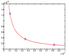 Figure 3: Curve of the energy with the three solutions (blue points).
4.2. Hydrogen energy graphics
From the Table 2, there are two different points which are the solution of (21). Because the values are nearer in each point, it is necessary to make the average of the values. The two points radius average, with different positions, have the same energy, they are reported in the Table 5
Table 5: energy corresponding to the two radius position average
| R (x10-10meter) | E41=e2X/(16R) (x10-30 Joule) |
| 2.8287 | 15.118 |
| 7.5639 | 15.118 |
In the Figure 4, the two average points occupy two different positions, supported by two different energy curves in 1/R, but possess the same energy . Also the radius axes coordinates are very small, atomic scale, because there is no correlation between the energy and the self-adjoint extension parameter.
4.3. Hydrogen energy graphics
The energy possess one solution value, because (27) has only one approximate best solution which is . The corresponding values of the cavity radius and the energy are reported on the Table 6
Table 6: values of the cavity radius and the energy
| R (x10-10meter) | E42=e2X/(16R) (x10-30 Joule) |
| 6.3500 | 15.118 |
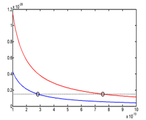 Figure 4: Curve of the energy E41(R) with the two solutions points, different positions and same energy.
The Figure 5 shows the behavior of the energy with function of the cavity radius, but the energy possesses only one value, equal to 15.118×10⁻³⁰ Joule, which is very small.
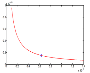 Figure 5: Energy E42 (R) behavior with function on the cavity radius R, and the point solution is fixed on the curve.
4.4. Hydrogen energies graphics
Expression (33) gives the relation between the energy with the self-adjoint extension parameter , and as well as it is known, greater make favorable the hydrogen storage. The calculations were made with three different values of this extension parameter. To be realist, the cavity radius dimension is set to be between 0 to 0.4 meter and the best dimension of one hydrogen tank is when its radius is equal to 0.2 meter. Also to have a great energy, extension parameter is take with great values about . The results values are report in the Table 7
Table 7: three values of the extension parameter generate three different values of the energy , when the cavity radius is equal to 0.2 meter
| R (meter) | E43= (γR+3)e2/(8R) (Joule) | γ (x1040) |
| 0.2 | 160 | 5 |
| 0.2 | 800 | 25 |
| 0.2 | 1600 | 50 |
Informatics processing of (33) and the graphic study of the function gives the Figure 6
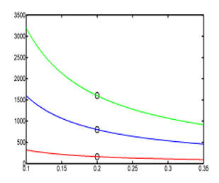 Figure 6: Three point values of the energy E43 (R) are marked
on three different curves of energy (in 1/R) with three different
values of the extension parameter .
5. Thermodynamic model
Thermodynamic properties of hydrogen storage systems, such as temperature and pressure, are required in order to evaluate and optimize their performance. The thermodynamic models of hydrogen storage systems are based on the mass and energy balance equations [14].
To simply model the hydrogen stored in a spherical cavity of radius , with taking into account the thermodynamic phenomena, the knowledge of the thermodynamic state functions and there states variables becomes necessary. It exists the intensive state variables as the temperature , the pressure , the density and the extensive state variables as the volume , the masse , the mole number or the mole number per unit volume
![]() where is the final volume of the tank.
where is the final volume of the tank.
5.1. Hypothesis
The volume of the spherical cavity of radius is define by the geometrical relation
![]() The clean or internal energy decrease with the radius according to the relation
The clean or internal energy decrease with the radius according to the relation
![]() Where is the solution of the polynomial equation obtained from the transcendental equation, it is define by (16).
Where is the solution of the polynomial equation obtained from the transcendental equation, it is define by (16).
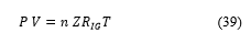
Hydrogen in state gas can appear as perfect gas or real gas, in practice the real gas is always used. The density of hydrogen at elevated pressure can be estimated using the principles of thermodynamics. While the behavior of most gases can be approximated with a high accuracy by the simple equation of state of an ideal gas with the constant
![]() that relates the pressure, the volume and the temperature of a given substance, the behavior of hydrogen deviates significantly from the predictions of the ideal gas model. The resulting deviation from the ideal gas law is always in the form of expansion – the gas occupies more space than the ideal gas law predicts. One of the simplest ways of correcting for this additional compression is through the addition of a compressibility factor, designated by the symbol . Compressibility factors are derived from data obtained through experimentation and depend on temperature, pressure and the nature of the gas. The factor is then used as a multiplier to adjust the ideal gas law to fit actual gas behavior as follows [15]
that relates the pressure, the volume and the temperature of a given substance, the behavior of hydrogen deviates significantly from the predictions of the ideal gas model. The resulting deviation from the ideal gas law is always in the form of expansion – the gas occupies more space than the ideal gas law predicts. One of the simplest ways of correcting for this additional compression is through the addition of a compressibility factor, designated by the symbol . Compressibility factors are derived from data obtained through experimentation and depend on temperature, pressure and the nature of the gas. The factor is then used as a multiplier to adjust the ideal gas law to fit actual gas behavior as follows [15]
 5.2. Thermodynamic functions
Replacing the volume expression, (36), in (39), the cavity radius is expressed with function on the pressure and the temperature
![]() The internal energy form is obtained by replacing the cavity radius (40) in (37).
The internal energy form is obtained by replacing the cavity radius (40) in (37).
![]() The internal energy is function of the pressure, the temperature, the compressibility factor and the mole number per unit volume. It increase with the pressure rising and it decrease when the temperature raise. Also, the inner energy is quantified by two parameters , the total energy in the tank storing hydrogen is the addition of all the individual energies corresponding to different states of the energy parameterized by the constant
The internal energy is function of the pressure, the temperature, the compressibility factor and the mole number per unit volume. It increase with the pressure rising and it decrease when the temperature raise. Also, the inner energy is quantified by two parameters , the total energy in the tank storing hydrogen is the addition of all the individual energies corresponding to different states of the energy parameterized by the constant
![]() The final cavity radius takes one realistic value manufacturing the tank
The final cavity radius takes one realistic value manufacturing the tank
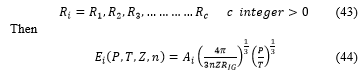 The partition function is then defined by the relation
 For the construct tank of hydrogen the radius is equal to then the true partition function take the form
![]() The free energy is then deduce from (46) by the relation
The free energy is then deduce from (46) by the relation
 The free energy is also function of the internal energy , the entropy and the temperature , with the following relation
 By substituting the and expression, respectively (41) and (48), in (50), the entropy takes the form
![]() The Gibbs energy is function of the free energy the pressure P and the volume , like
The Gibbs energy is function of the free energy the pressure P and the volume , like
![]() By replacing V and F with their expressions, (36) and (48), in (51)
By replacing V and F with their expressions, (36) and (48), in (51)
![]() Then taking into account of the radius r (40),
Then taking into account of the radius r (40),
![]() The chemical potential is define like
The chemical potential is define like
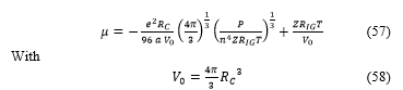
 The calculation arrive to the final expression
 6. Graphic processing
The data are set with the following values in the international unit system (IS):
the Bohr radius is , the constant of real gas is , the mole number per unit volume is equal to the Avogadro number , the cavity radius and from (37) the constant .
The values of the compressibility factor were taken from the experimental curve of the compressibility factor as a function of the pressure at different temperatures [15]. The experimental data are shown in Table 8
Table 8: dataset for calculations
|
P (Bar) |
0 |
50 |
100 |
200 |
300 |
400 |
500 |
600 |
|
| T1=100 (K) | |||||||||
| Z1 | 1 | 0.98 | 1.06 | 1.22 | 1.44 | 1.66 | 1.88 | 2.05 | |
| T2=150 (K) | |||||||||
| Z2 | 1 | 0.98 | 1.08 | 1.18 | 1.32 | 1.46 | 1.59 | 1.72 | |
| T3=200 (K) | |||||||||
| Z3 | 1 | 0.98 | 1.08 | 1.16 | 1.26 | 1.36 | 1.46 | 1.56 | |
| T4=300 (K) | |||||||||
| Z4 | 1 | 0.99 | 0.98 | 1.07 | 1.12 | 1.18 | 1.25 | 1.39 | |
6.1. Energy with function on the pressure and the temperature
Knowing the energy relation as function of the pressure and the temperature (59)
![]() The curves of the energies are shown in the Figure 7
The curves of the energies are shown in the Figure 7
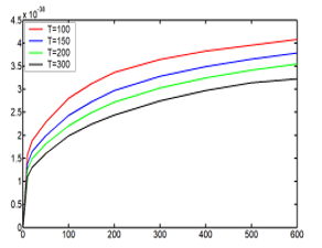 Figure 7: Energy, (59), as function of the pressure and the temperature.
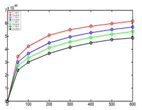 Figure 8: Energy with function of the pressure and the temperature including the experimental points.
Considering the experimental values of the compressibility factors, and with one scale factor equal to , the curves were adjusted using the function of the energy (59). The Figure 8 shows the behavior of the energies with the experimental values of the compressibility factor.
7. Conclusion
This article has examined the hydrogen storage phenomenon in a spherical cavity. Especially the hydrogen gas subjected to high pressures, leading to significant loss of mass of hydrogen, and requiring materials that can withstand these high pressures and minimize losses. For all these reasons, the problem is considered at the quantum scale. So the first part of the article is dedicated to the quantum mechanics, it studies the theory of the radial functions corresponding to the hydrogen by resolving the Schrödinger equation with adding the boundary condition of Robin. The second part was devoted to solving the transcendental equation that is the result of the first part and has resulted in the relations of the energies. The mathematical studying of the transcendental equation has given three polynomial equations which are independent on the self-adjoin extension parameter. The energies in this case are very small, E40 # E41 # E42 # 1.10-28 Joule. Only the case where the energy E43 is function of the self-adjoint extension parameter is acceptable and important. This energy is estimated between 160 J and 1600 J, because of the high value of the self-adjoint extension parameter about 1.1040. The conclusion from this part is that all the energies depend on the radius R of the cavity according to the form (Constant/R). The third part studies the thermodynamic modeling, which made it possible to express all the thermodynamic functions with function of the pressure and the temperature. With considering the experimental curve of the compressibility factor as a function of the pressure at different temperatures, the expression of the energy was adjusted very well with the model of the theoretical energy. The energy increase with the pressure P rising and decrease with the increasing of the temperature T. This made it possible to validate the model, since there is a perfect agreement between the experimental values of energy and the theoretical model.
- Sofoklis S. Makridis, Hydrogen storage and compression, Methane and hydrogen for energy storage, Chapter 1 p 4, CH001, eprint arXiv: 1702.06015, 02/2017.
- Durbin DJ, Malardier-Jugroot C, Review of hydrogen storage techniques for on board vehicle applications. International Journal of Hydrogen Energy 2013; 38:15595–14617.
- U. Bossel, Renewable Energy World, March-April (2004) 155-159.
- M.H.Al-Hashimi, U.-J. Wiese, Self-adjoint extensions for confined electrons: From a particle in a spherical cavity to the hydrogen atom in a sphere and on a cone, Annals of Physics 327, 2012, 2742-2759.
- Ravindra Shinde and Meenakshi Tayade, Remarkable Hydrogen Storage on Beryllium Oxide Clusters:First Principles Calculations, Maharashtra 400076, INDIA., and Mumbai, Maharashtra 400019, INDIA, 25 Jul 2016.
- D. Harrison, E. Welchman and T. Thonhauser, H4-Alkanes: A new class of hydrogen storage material? Department of Physics, Wake Forest University, Winston-Salem, NC 27109, USA. 22 May 2017.
- Vito Dario, Camiola Riccardo Farchioni,Tommaso Cavallucci, Antonio Rossi, Vittorio Pellegrini, ValentinaTozzini, Hydrogen storage in rippled graphene: Perspectives from multi-scale simulations, Pisa Italy, 2013.
- Sarah Goler, Camilla Coletti, Valentina Tozzini, Vincenzo Piazza, Torge Mashoff, Fabio Beltram, Vittorio Pellegrini, and Stefan Heun, The Influence of Graphene Curvature on Hydrogen Adsorption: Towards Hydrogen Storage Devices, Piazza San Silvestro 12, 56127, Pisa Italy, 2010.
- Kelly NA,Gibson TL, Cai M, Spearot JA, Ouwerkerk DB, Development of a renewable hydrogen economy: optimization of existing technologies. International Journal of Hydrogen Energy 2010; 35:892–899.
- Jain IP, Hydrogen, the fuel for the 21st century. International Journal of Hydrogen Energy 2009; 34:7368–7378.
- Wang X, Chen R, Zhang Y, Chen C, Wang Q, Hydrogen storage alloys for high-pressure supra-pure hydrogen compressor. Journal of Alloys and Compounds 2006; 420:322–325.
- Hui L, Xinhua W, Zhaohui D, Lou X, Changpin C, A study on 70MPa metal hydride hydrogen compressor. Journal of Alloys and Compounds 2010; 502:503–507.
- S.S. Makridis, E. Gkanas, G. Panagakos, E.S. Kikkinides, A.K. Stubos, P. Wagener and S. Barcikowski, Polymer-Stable Magnesium Nanocomposites Prepared By Laser Ablation For Efficient Hydrogen Storage. International Journal of Hydrogen Energy 30 August 2013; Volume 38, Issue 26, Pages 11530-11535.
- Xiao J, Bénard P, Chahine R, Charge-discharge cycle thermodynamics for compression hydrogen storage system. International Journal of Hydrogen Energy 41 (2016), pp. 5531-5539.
- Hirscher M (ed.). Handbook of hydrogen storage: new materials for future energy storage. Weinheim: Wiley-VCH Verlag GmbH & Co. KgaA; 2010.