A Wi-Fi based Architecture of a Smart Home Controlled by Smartphone and Wall Display IoT Device

Adv. Sci. Technol. Eng. Syst. J. 3(6), 180–184 (2018);
 DOI: 10.25046/aj030623
In this age of smart devices, many people are carrying a smartphone with them all the time. When they are at home, most of them are connected with the home Wi-Fi network. In this paper, a Wi-Fi network based architecture is proposed to control home appliances using a smartphone and also with a touchscreen-based wall display panel. The proposed system enables the user to control appliances from anywhere in the home without the pain of walking towards the switch panel on the wall. In this project, the mechanical switch based panel on the wall is replaced by the state-of-the-art touch-based liquid crystal display. Along with buttons, the display also shows current weather and time widgets. The smartphone app and a prototype of the display panel using Raspberry Pi with Android Things operating system is developed and tested.
1. Introduction
In a recent survey, respondents said that Wi-Fi Internet is more important to them than television, alcohol, sex, and everything else besides food. In this age of smart devices, many people – both young and adult – are carrying a smartphone with them all the time. When they are at home, most of them are connected with the home Wi-Fi network. Homes today have an average of 8 devices connected to the Wi-Fi and at the end of 2019, households worldwide will have more than 10 billion devices capable of connecting to their home network router [1]. Globally, total public Wi-Fi hotspots will grow sevenfold from 2015 to 2020, from 64.2 million in 2015 to 432.5 million by 2020. Wi-Fi hotspots will be key for the development of the Internet of Things (IoT) applications and services [2].
A smart home is equipped with electronic devices, such as sensors, microprocessors, relays, and appliances – that are tied to a network and controlled via interfaces such as phones, webs, or embedded computers [3], [4]. In this paper, a Wi-Fi network based smart home architecture is proposed to control home appliances using a smartphone and also with a touchscreen-based wall display IoT device. The proposed system enables the user to control appliances from anywhere in the home using a smartphone app – without the pain of physically walking towards the switch panel on the wall. In the proposed system, the smartphone acts as a remote control for the home appliances. With the smartphone in hand – the appliances can be operated while lying on the bed, sitting on the couch, or even during eating – without the need of line-of-sight of traditional infrared based remotes. In this project, the mechanical switch based panel on the wall is also replaced by the state-of-the-art touch screen based liquid crystal display (LCD) unit which is connected to Wi-Fi. The display shows buttons and also shows the current weather and time widgets. The smartphone app and a prototype of the wall display unit using Raspberry Pi with Android Things operating system is developed and tested.
2. Related Work
Several recent related works are found in the literature about the design and architecture of a smart home. In [5], dual tone multi-frequency (DTMF) is used to control the home appliances remotely via a GSM network. The idea is to employ a DTMF decoder through which home appliances can be controlled by dialing a predefined number, via smartphone, for a specific load. In [6], the proposed hardware architecture is composed of remote user application terminals, the terminal control unit and various terminals distributed in different rooms. The communication between the terminal control unit and the field terminals is implemented using ZigBee technology and GSM/GPRS module is used for information transmission of sensor data and remote commands. Remote users can browse the household temperature and humidity data using a mobile app or the web page. Here, the proposed work can only do monitoring, but unable to control loads. In [7], a smart home environment monitoring system is designed with Raspberry Pi based smart home controller, EnOcean/Wi-Fi wireless sensor control network, and smart home PC client. In [8], a solution is developed to control home appliances like light, fan, door cartons, energy consumption, and level of the Gas cylinder using various sensors and microcontrollers such as Node MCU ESP8266 and Arduino UNO. It provides information about the energy consumed by the house owner regularly in the form of message. Also, it checks, the level of gas in the gas cylinder – if it reaches lesser than the threshold, it automatically places the order for refill gas cylinder and sends a reference number as a message to the house owner. However, load control using a smartphone app and using wall display panel is not discussed in [7] and [8]. In [9], the design of a Smart Power Strip is discussed where the loads can be turned on/off using a smartphone app that communicates wirelessly with the microcontroller using Bluetooth. In [18], a smart home architecture is proposed using ZigBee, Wi-Fi, and Ethernet. Here a ZigBee to Wi-Fi data conversion service is required, where the proposed work in this paper only uses Wi-Fi and do not require the network protocol conversion overhead. The work in [19] uses Arduino Ethernet, where this work uses Raspberry Pi with the state-of-the-art Android Things operating system for controlling the loads.
Compared with the other works, the proposed work uses the home Wi-Fi network. As most of the smart devices such as smartphones, tablets etc. are always connected with home Wi-Fi, no additional connection such as Bluetooth, ZigBee etc. are required – which can save battery life of the phone. Using the proposed system, electrical loads can be turned on/off using both smartphone app and a Wi-Fi connected LCD with a touchscreen device that can be attached on the wall – replacing the old-fashioned mechanical switch based panel. The wall display also shows colorful weather forecast and time widgets. To use the proposed system, the password of the home Wi-Fi network must be known to the user – thus the system is fairly secured from hacking.
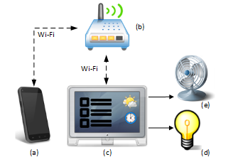 Figure 1: The architecture of the proposed system: Smartphone (a) connected to the wireless router (b) using Wi-Fi. The Raspberry Pi based IoT display panel (c) connected with the router (b), showing buttons, weather and time widgets. Loads (d) and (e) are connected with the Raspberry Pi ports of the display panel using solid state relays.
3. System Architecture
The overall architecture of the proposed system is shown in Figure 1. In Figure 1., the smartphone (a) and the wall display panel (c) gets connected to the wireless router (b) using Wi-Fi. Loads such as light (d) and fan (e) are connected with the wall display panel using solid state relays (SSR). The loads can be turned on/off by using the buttons of the display panel. The display panel also shows weather and time widgets. Loads can also be controlled using the Smartphone app wirelessly. A brief description of the Wi-Fi connected wall display panel and the smartphone app are given below.
3.1. Wall Display Panel
In the proposed system, the mechanical switch based panel on the wall is also replaced by the state-of-the-art touch screen based LCD unit which is connected with Wi-Fi. The display also shows current weather and time widgets. The hardware and software parts of the device are described below.
Hardware: The hardware architecture of the display panel is shown in Figure 2. A Raspberry Pi (RPi) v3 [10] single board computer is used as the main processing unit. It containing a 1.2 GHz 64-bit quad-core ARMv8 microprocessor, 1 GB of RAM, micro SD card slot supporting up to 32 GB, 40 general purpose input output (GPIO) pins with two pulse width modulation (PWM) module, onboard Wi-Fi module, and other built-in hardware peripherals such as universal asynchronous receiver/transmitter (UART), I2C, serial peripheral interface (SPI), universal serial bus (USB), audio output via 4-pole 3.5mm connector, LCD interface (DSI) etc. A 7-inch capacitive touch LCD [11] is interfaced with the RPi using the DSI and the I2C port. The LCD has 24-bit color depth and the screen resolution of 800 × 480 pixels.
Two solid-state relays (SSR) [12] are used, as shown in Fig. 2., to control the AC loads. The SSRs are controlled by two GPIO pins – GPIO18 and GPIO13 – of the RPi. The contact of the SSR can carry a maximum of 40 A current. Finally, the power supplies for the RPi board and the touch LCD are supplied using 110V AC to 5.1V DC adapters [13].
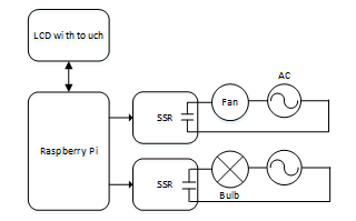 Figure 2: Block diagram of the wall display panel hardware.
App: The Android Things [14] embedded operating system is installed on a 16 GB secure digital (SD) card of the RPi board. Android Things is recently developed by Google, aimed to be used with low-power and memory constrained IoT devices. The platform can run any program targeting Android and it also comes with libraries for accessing hardware peripherals such as UART, I2C, and GPIO of the RPi. The device gets connected to the home Wi-Fi and can access the Internet.
The app of the display panel shows the on and off buttons for each load. The current on-off status is also displayed using labels. The display panel also shows the current time and weather widget on the screen. Hypertext Markup Language (HTML) code was embedded in web views of the app for fetching time [15] and weather [16] information from the Internet.
The wall display panel is configured as a server and the smartphone is configured as a client for socket-based data communication in the local Wi-Fi network. The display panel’s app shows its local Internet Protocol (IP) address, so the user can input that IP in the smartphone to establish a socket connection. The dynamic host configuration protocol (DHCP) server of the router dynamically assigns IP to its connected devices, so the IP address of the display panel may change on a new connection depending on how many devices are currently connected with the router. If IP of the display panel changes, then the user needs to re-enter the IP in the smartphone app to establish a socket connection each time– which is tiresome. To solve this problem, the IP of the display panel is fixed to 192.168.1.20 by configuring the router [17], so that the smartphone does not have to reenter the display panels IP.
Whenever On/Off button is pressed for a particular load in the display panel, a status file – named status.dat – is updated with the new value. This file contains the on-off status of all the AC loads. Then depending upon the content of the status.dat file, GPIO pins are either set or reset. After that, the labels showing the status of the loads are updated based on the status.dat file. If the display panel is already connected to the smartphone, then the load status is synchronized with the smartphone. To do that, a command data frame, as shown in Figure 3, is sent to the smartphone using socket-based data communication.
![]() Figure 3: Command data frame.
Figure 3: Command data frame.
In Figure 3, CMD is a byte containing the nature of the command or the response. When the display panel sends its status to the smartphone, the CMD field contains the constant CMD_SERVER_RESPONSE. The Is On Off_<n> contains the Boolean on-off status; here <n> represents the load ID. After the phone receives the command frame, it updates its status with the new values and the status is synchronized with the smartphone.
3.2. Smartphone App
The smartphone app is developed for the Android platform. The first screen of the app shows the on and off buttons for each load. The current on-off status is also displayed using labels. The app contains a settings menu, where the user can input the IP of the wall display panel. The first screen of the app contains a connect button – when pressed by the user – a socket connection is established with the display panel through the router using Wi-Fi.
After the smartphone gets connected with the display panel using the socket connection for the first time, the phone sends a request to the display panel to get the current status of the loads. To do that, the smartphone sends a command data frame where the CMD field contains the constant CMD_GET_STATUS and the remaining fields contain don’t care values. After receiving the CMD_GET_STATUS command, the display panel app reads the contents of the status.dat file and makes a command frame where CMD field is set to CMD_SERVER_RESPONSE and the remaining fields contain the status of the loads. The command is then sent and after the phone receives the data frame, it updates its status with the new values and the status is synchronized.
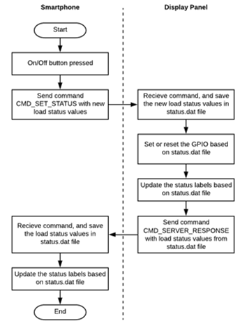 Figure 4: Flowchart when on/off button is pressed in the smartphone.
Whenever On/Off button is pressed for a particular load in the smartphone, the app makes a command frame – where CMD field contains the constant CMD_SET_STATUS and remaining fields contain the new values for the loads. The command is then sent to the display panel using socket connection. When CMD_SET_STATUS command is received, the display panel app updates the status.dat file with the new values. Then depending upon the status.dat file – the display panel updates the GPIO pins, updates the status labels and then sends a response data frame to the phone where the CMD field contains the constant CMD_SERVER_RESPONSE and remaining fields contains the new status of the loads. After the phone receives the data frame, it updates its status with the new values, stores them in the status.dat file, updates the status labels and status is synchronized. The flowchart of the operation is shown in Figure 4.
4. Result
A prototype of the proposed Wi-Fi-based smart home control system as discussed in Section 3 is developed and tested successfully. The photograph of the experimental setup is shown in Figure 5. Loads can be controlled using the display panel and also with the smartphone with a 100% success rate. The status of the smartphone app automatically gets updated when a load is controlled by the display panel and vice-versa.
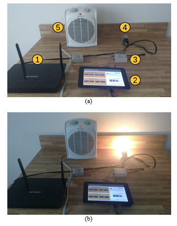 Figure 5: The experimental setup: (a) wireless router (1), wall display IoT device (2), SSR (3), Bulb at off state(4), Fan at off state (5); (b) Bulb and fan at on state.
The wall display panel IoT device, as shown in Figure 6, is developed as discussed in Section 3.1. This display device replaces the mechanical switches and loads – such as light and fan – can be controlled by pressing buttons on the touchscreen. It also shows current time and weather gadgets. It is possible to add more than two loads with the other GPIO pins of the RPi.
The smartphone app is developed according to the discussion in Section 3.2. A screenshot of the first screen of the smartphone app is shown in Figure 7. The app shows the on and off buttons, and the current on-off status for each load. The app contains a connect button and also shows the connection status with the display panel.
5. Conclusion
In this paper, a Wi-Fi network based architecture to control home appliances using a smartphone and also with a touchscreen-based wall display panel IoT device is proposed. Using the smartphone, the user can control appliances from anywhere in the home. A prototype of the proposed system is developed and tested.
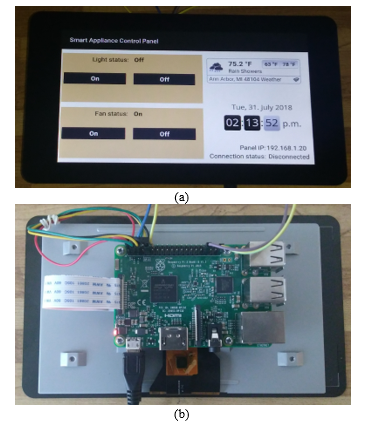 Figure 6. The wall display IoT device: (a) Top view – showing on-off buttons for each load, load and connection status, current time, and weather gadgets. (b) Bottom view –Raspberry Pi board interfaced with LCD and SSR.
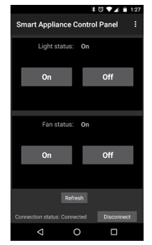 Figure 7. Screenshot of the smartphone app
Future work includes controlling the brightness or speed of the load using PWM, a cloud-based web interface for controlling and monitoring the loads and interfacing temperature and humidity sensors with the display panel.
- The Home Network: Our Neglected Workhorse. [Online], Available: http://www.linksys.com/resources/img/features/ea8500/The_Home_Internet_Network_IDC_Brief.PDF, 2015
- Facts and stats about Wi-Fi. [Online], Available: http://worldwifiday.com/about-us/facts/, 2018
- C. Paul, A. Ganesh and C. Sunitha, “An overview of IoT based smart homes,” 2018 2nd International Conference on Inventive Systems and Control (ICISC), Coimbatore, India, 2018, pp. 43-46.
- A. Zanella, N. Bui, A. Castellani, L. Vangelista and M. Zorzi, “Internet of Things for Smart Cities,” in IEEE Internet of Things Journal, vol. 1, no. 1, pp. 22-32, Feb. 2014.
- R. A. Johar, E. Fakieh, R. Allagani and S. M. Qaisar, “A smart home appliances control system based on digital electronics and GSM network,” 2018 15th Learning and Technology Conference (L&T), Jeddah, 2018, pp. 52-58.
- Z. Xiaodong and Z. Jie, “Design and implementation of smart home control system based on STM32,” 2018 Chinese Control And Decision Conference (CCDC), Shenyang, China, 2018, pp. 3023-3027.
- X. Wen and Y. Wang, “Design of smart home environment monitoring system based on raspberry Pi,” 2018 Chinese Control And Decision Conference (CCDC), Shenyang, China, 2018, pp. 4259-4263.
- H. Singh, V. Pallagani, V. Khandelwal and U. Venkanna, “IoT based smart home automation system using sensor node,” 2018 4th International Conference on Recent Advances in Information Technology (RAIT), Dhanbad, 2018, pp. 1-5.
- K. Laubhan, K. Eggenberger, T. Khan and K. Yelamarthi, “Design of a smartphone operated powerstrip,” 2017 IEEE International Conference on Electro Information Technology (EIT), Lincoln, NE, 2017, pp. 317-320.
- Raspberry Pi, [Online]. Available: https://www.raspberrypi.org, 2018.
- Raspberry Pi LCD – 7″ Touchscreen, [Online]. Available: https://www.sparkfun.com/products/13733, 2018.
- Solid State Relay, [Online]. Available: https://www.sparkfun.com/products/13015, 2018.
- DC Power Supply, [Online]. Available: https://www.sparkfun.com/products/13831, 2018.
- Android Things, [Online]. Available: https://developer.android.com/things/get-started/index.html, 2018.
- Clock widget, [Online]. Available: https://www.zeitverschiebung.net/en/clock-widget, 2018.
- Weather widget, [Online]. Available: https://www.willyweather.com/widget/create.html, 2018.
- How do I reserve an IP address on my NETGEAR router? [Online]. Available: https://kb.netgear.com/25722/How-do-I-reserve-an-IP-address-on-my-NETGEAR-router, 2018.
- C. Y. Chang, C. H. Kuo, J. C. Chen, and T. C. Wang, “Design and Implementation of an IoT Access Point for Smart Home,” Appl. Sci. vol. 5, 2015, pp. 1882-1903.
- R. Piyare, “Internet of Things: Ubiquitous Home Control and Monitoring System using Android based Smart Phone,” International Journal of Internet of Things, vol. 2, no. 1, 2013, pp. 5-11.