Guidance Law Based on Line-of-Sight Rate Information Considering Uncertain Modeled Dynamics

Adv. Sci. Technol. Eng. Syst. J. 3(6), 195–203 (2018);
 DOI: 10.25046/aj030626
Proportional navigation (PN) is a widely-used guidance law for missiletarget engagement. The goal of the missile intercept problem is to reduce the closest distance between the missile and target by diminishing the line-of-sight rate (LOS rate). In general, PN guidance law necessitates information of the LOS rate and missile velocity. The closing velocity (relative approaching speed to the target) instead of the missile velocity is an additional option for effective guidance. However, there are cases where a sensing device for measuring target motions that can be mounted on a missile is limited. In this paper, we propose a novel guidance law on the basis of proportional navigation (PN) using only line-of-sight (LOS) rate information. In this paper, an uncertainty and disturbance estimator (UDE) is applied to estimate such target motions including velocity change or unpredictable movement etc. The UDE works also for compensating uncertain modeled dynamics such as a missile’s bearing uncertainty and velocity changes. The proposed guidance law is referred to as uncertainty and disturbance-compensated intercept guidance. Numerical simulations with some engagement scenarios are presented taking account of the velocity changes of the missile to demonstrate the potential of the proposed guidance law.
1. Introduction
Proportional navigation (PN) is a widely-used guidance law for terminal interception of target-missile engagement [1], and the guidance law attracts attention since the first half of the 20th century. Researches have been conducted not only for missile guidance, but also in the fields such as the guidance of vehicles [2], the formation flight of aircraft [3], small UAVs autonomous path-following [4], furthermore the problem of rendezvous of satellites and terminal guidance control to a small moon landing [5, 6].
Proportional navigation (PN) is mainly classified into two; (1) true proportional navigation (TPN) using closing velocity information and (2) the pure proportional navigation (PPN) using the missile’s velocity information [7]. Both laws use information on the lineof- sight (LOS) rate (rate of change in the direction of a line connecting a missile and a target) and the velocity of the missile (if it is obtained, using the closing velocity to the target). The PN is widely used as a guidance law for the intercept in two-vehicle engagement ary or non-maneuvering target, without measurement error, dynamics lag, nor lateral acceleration limit on the navigation system of the missile, the PN can completely intercept the target with zero miss distance. For such a reason, researches on missile guidance have been conducted based on the PN or alternative representation such as the zero-effort-miss (ZEM) guidance. For instance, the augmented proportional navigation (APN) compensates a target lateral constant acceleration by adding a modified acceleration term to the PN law [8]. The compensated PN [9] (or velocity changecompensated PN [10]) guides missiles to keep the LOS rate constant at zero by correcting the LOS rate change produced by the missile’s axial acceleration.
In [11], optimal theory on intercept guidance provides that the effective navigation constant of the PN set to three is an optimal against the non-maneuvering target in the sense of the least squared integral of the lateral accelerations. The preceding guidance system does not take dynamics-lag into account while an optimal guidance for a first-order time-lag system is given in [8]. The guidance law in [8] that minimizes the squared integral of the commanded lateral acceleration of the missile uses the target lateral acceleration information. In addition, in this optimal guidance law (referred to as OG in this paper), a variable gain is used instead of the constant value, and the variable gain can be expressed as a function of the time-to-go (the time remaining till interception). In this regard, the suboptimal guidance (SOG) law was proposed using PN with phase lead compensation by Baba et al. [12]. The optimal or suboptimal guidance laws described so far are effective under the assumption where the closing velocity information is available. Sensing device for target information may depends on the missile’s operations. There are cases where the missile cannot install an equipment measuring the closing velocity. Therefore, in this study, we focus on the case where only LOS rate can be acquired as for target maneuvers-related information other than that of the missile itself.
Since the closing velocity cannot be obtained while only LOS rate is used, the usual fixed gain approach in PN may not exhibit sufficient guidance performance. Here, we focus on the LOS rate dynamics in order to enhance or keep the guidance performance under restricted conditions where only information as for the target is to be the LOS rate. We proposed a new guidance law that drives the LOS rate to be zero, estimates and compensates an uncertain group including unmodeled dynamics and external [13]; In [13], the authors did not consider time-lag in system response, so we present results for a time-lag system [14]. Furthermore, this study demonstrates the robustness of the proposed guidance affected by the axial acceleration by the missile thrust and the deceleration due to
aerodynamic drag.
The rest of this paper is organized as follows: Section 2 details the setting of the guidance problem with notation assignments for the missile-target engagement, followed by the governing equations. Next, a guidance law, which is based on an assembled simple LOS rate dynamics model, is developed. In Section 3, numerical simulation results are shown to demonstrate the potential of the proposed guidance law. Section 4 summarizes this study.
2. Guidance Theory
2.1. Engagement problems and Governing equations
This section introduces the notations, assumptions, governing equations for the guidance law, and defines the engagement problem.
Figure 1 shows a missile-target geometry and their related notations for deriving the guidance law for the missile-target engagement scenario. Here after, the guided vehicle is referred to as a missile. λ denotes the LOS angle ,and R is the LOS range. V , γ and a for each vehicle represents the velocity, flight path angle, and lateral acceleration, respectively. The subscripts for these variables distinguish the missile from the target; with “m” for the missile, and “t” for the target.
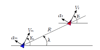 Figure 1: Engagement Geometry
Assumptions are made for the derivation of the proposed guidance law as
- The missile and target are point masses, moving in a plane.
- The target moves with a constant speed.
- The LOS rate is available without error.
- The response lag to the commanded lateral acceleration for the missile can be represented by a first-order-lag system.
Under these assumptions, the governing equations on the missile-target engagement can be summarized as
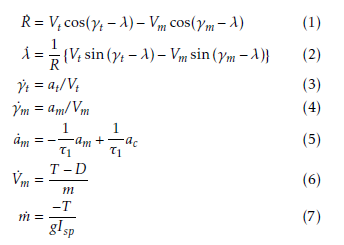 where ac is a commanded value of missile’s lateral acceleration, and system response am is approximated by the output from a first-order-lag system with the time constant τ1. Also T , D, Isp and g denote the missile’s thrust, drag force, and specific impulse, and the gravitational acceleration, respectively. For additional variables for simulations, the lift denoted by L and the drag-related equations are shown as;
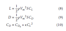 where ρ is the air density, S is the cross sectional area, CL, CD, CD0, and κ denote the lift coefficient, the drag coefficient, the zero-lift drag coefficient, and the induced drag-related parameter, respectively.
If the LOS angle λ is maintained constant, the missile can intercept the target [1, 8]. That is, the problem for deriving the guidance law on missile-target engagement is to calculate the commanded lateral acceleration for missile, ac, which will bring the LOS angular velocity (the LOS rate) λ˙ to zero. Thus, the objective of this study is to find ac nullifying the LOS rate without using information of the closing velocity.
2.2. Construction of a simplified dynamics model
In designing a guidance system, the construction of a dynamics model plays an important role. An accurate model is indispensable to build a high precision guidance. On the other hand, a designed guidance system with such an accurate model tends to become a complicated and high-order system, and to demand multiple sensors and/or estimators. For this reason, we try to use a simplified guidance model as much as possible aiming at simplifying the design process for a guidance system that uses only information of the LOS rate.
In order to design a guidance system, this study focuses on a mathematical model representing the LOS rate dynamics. By differentiating Eq. (2) and substituting Eqs. (1), (3) and (4), the LOS rate dynamics model is derived in the following differential equation form;
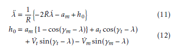 The term h0 in the preceding Eq. (12) includes ”model uncertainty” arising from mathematical simplifications, and ”disturbance” caused mainly from uncertain target accelerations or maneuvers. Hereafter, the term h0 including such model uncertainty and external disturbance is called an uncertainty and disturbance term (UDT).
In [15], Eq. (11) is used as a system equation for the development of the guidance logic. However, Eq. (11) includes not only the available LOS rate but also the LOS range and the closing velocity (Vc = −R˙) that cannot be measured or estimated. Instead of Eq. (11), in order to take account of the restriction where only the LOS rate is available, this study uses the following equation;
 where R0 is a given parameter in advance, for example the reachable flight range of the missile or the initial value of the LOS range. The UDT (h0) of Eq. (11) and additional uncertain terms caused from this simplification are combined as
![]() The estimation of the UDT (h) is explained in Section
The estimation of the UDT (h) is explained in Section
In this study, the command lateral acceleration ac is considered as the input to the guidance system while taking account of the missile dynamics which is approximated as a first-order-lag system. In the guidance system, the LOS rate λ˙ and the lateral acceleration of the missile am are treated as state variables. Thus, the lateral acceleration am is treated as an intermediate variable for a backstepping approach. The purpose of this guidance system can be interpreted as ”driving the first state variable λ˙ to zero with the input of ac”. A method for calculating the input ac driving the first state variable to zero will be described in the next section.
2.3. Derivation of uncertainty and disturbance-compensated guidance
In this section, we explain the derivation of uncertainty and disturbance-compensated guidance based on the governing Eqs. (5) and (13). The guidance law should drive the LOS rate λ˙ to zero with the lateral commanded acceleration ac as described in the previous section. However, the first state variable cannot be directly controlled by the lateral acceleration commanded value ac. Therefore, this study uses the backstepping method to control the LOS rate λ˙ via the intermediate state am. A candidate of the Lyapunov function is defined as
![]() where, for simplicity, the LOS rate λ˙ is defined as σ.
where, for simplicity, the LOS rate λ˙ is defined as σ.
When Eq. (15) is differentiated with time, it becomes
 The estimated value of the UDT h is defined as hˆ. Moreover, the desired missile lateral acceleration amd is set as
![]() On the other hand, addition and subtraction of amd/R0 to Eq. (13) and making (amd − am) term lead to
On the other hand, addition and subtraction of amd/R0 to Eq. (13) and making (amd − am) term lead to
![]() Substituting Eq. (17) for the first term of Eq. (18) provides
Substituting Eq. (17) for the first term of Eq. (18) provides
![]() Substituting Eq. (19) for the first equality in Eq. (16), it is found that
Substituting Eq. (19) for the first equality in Eq. (16), it is found that
![]() If the lateral acceleration am converges to the desired lateral acceleration amd, and when the UDT(h) can be estimated without error, that is, hˆ→h, the Eq. (20) is expressed as V˙ ≈ −kσ2 ≤ 0 (the equality holds when σ = 0). Consequently, if k is positive, V can be called as the Lyapunov function. For this reason, the LOS rate σ converges to zero as the lapse of time.
If the lateral acceleration am converges to the desired lateral acceleration amd, and when the UDT(h) can be estimated without error, that is, hˆ→h, the Eq. (20) is expressed as V˙ ≈ −kσ2 ≤ 0 (the equality holds when σ = 0). Consequently, if k is positive, V can be called as the Lyapunov function. For this reason, the LOS rate σ converges to zero as the lapse of time.
In order to make am close to amd, a new candidate
Lyapunov function is defined as
![]() From the observation of Eqs. (5), (17) and (22),commanded lateral acceleration can be selected as
From the observation of Eqs. (5), (17) and (22),commanded lateral acceleration can be selected as
![]() If it can be approximated as a˙md ; 0 and the estimated value become hˆ→h, Eq. (22) becomes
If it can be approximated as a˙md ; 0 and the estimated value become hˆ→h, Eq. (22) becomes
![]() that shows V˙1 ≤ 0.
that shows V˙1 ≤ 0.
Equations (17) and (23) represent the guidance law.
Excepting the estimated value hˆ of the UDT in Eqs.
(17) and (23), the guidance law includes terms proportional to the LOS rate without the closing velocity: Eqs. (17) and (23) essentially includes the PN guidance law.
For comparison purpose to the proposed guidance law, the conventional guidance laws are illustrated next, which clarifies what kind of extra information is required for each guidance law.
The PN guidance law that uses missile velocity instead of the closing velocity (what is called ’pure PN (PPN)’) is represented as [16]:
![]() where N denote the navigation constant. The lateral acceleration is assumed to be generated perpendicular to the velocity vector in the PPN guidance law. In this research, the closing velocity information cannot be obtained. However, if this is obtained, it is effective to use the closing velocity Vc instead of the missile ve-
where N denote the navigation constant. The lateral acceleration is assumed to be generated perpendicular to the velocity vector in the PPN guidance law. In this research, the closing velocity information cannot be obtained. However, if this is obtained, it is effective to use the closing velocity Vc instead of the missile ve-
locity Vm of the Eq. (25). Thus, the command lateral acceleration of PN guidance law is
![]() where N0 is the effective navigation constant [16]. According to the optimal control theory as described in the introduction [11], if the missile has perfect dynamics (it has no response lag), and the target has constant-speed with rectilinear motion, when the effective navigation constant is 3 (N0 = 3), the input of command lateral acceleration is minimizing the square integral of acceleration.
where N0 is the effective navigation constant [16]. According to the optimal control theory as described in the introduction [11], if the missile has perfect dynamics (it has no response lag), and the target has constant-speed with rectilinear motion, when the effective navigation constant is 3 (N0 = 3), the input of command lateral acceleration is minimizing the square integral of acceleration.
The augmented PN (APN) guidance law is a wellknown optimal guidance law against the constant maneuvering target. The target’s constant lateral acceleration-related term is added to the TPN guidance law as [8]
 where aT indicates the target maneuver (lateral acceleration which is assumed to be normal to the LOS) [15].
Furthermore, the optimal guidance law (OG) is derived based on the optimal control theory for a liner system in case where the response of the system can be approximated by a first-order-lag;
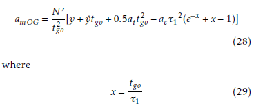
Also, y indicates a component perpendicular to the initial LOS. y is subtraction of the missile position component from the target one with respect to the initial LOS. If y is sufficiently small, the relationship of trigonometric ratio provides
![]() The following relationship can be obtained by differentiating both sides of Eq. (30).
The following relationship can be obtained by differentiating both sides of Eq. (30).
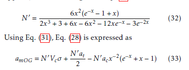
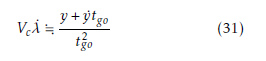 The numerator in the right hand side in Eq. (31) is called ZEM (the miss distance with no guidance force applied). The variable gain in Eq. (28) is derived as
 In the simulation of this paper, these commanded acceleration (Eqs. (25) ∼ (27) and Eq. (33)) are used to compare with the proposed guidance law.
k of the proposed guidance law (Eq. (17)) is a pos-
itive constant to be tuned. Some design policy can be helpful. In this study, the gain is determined as compared with PN guidance law of Eq. (25) as
![]() where R0 is a pre-specified value; it could be the initial LOS range or the possible flight range. Vm0 and N denote the assumed average velocity of the missile and the navigation constant, respectively. In this proposed guidance law, N is the main tuning parameter.
where R0 is a pre-specified value; it could be the initial LOS range or the possible flight range. Vm0 and N denote the assumed average velocity of the missile and the navigation constant, respectively. In this proposed guidance law, N is the main tuning parameter.
2.4. Estimation of the uncertainty and disturbance term
We describe the estimation method [15, 17, 18] for UDT h in this section.
As for the UDT estimation, assembled term for uncertainty and disturbance in a focused system dynamics are estimated based on the system dynamics. For example, a discrete-type method, so-called time delay control (TDC) [19, 20] was proposed for an uncertainty and disturbance compensator. The TDC technique, however, arose a potential problem; since the time derivative in TDC is approximated with numerical differentiations, instability of the system may occur. In [17], a frequency-domain-based approach that can be treated in continuous system were proposed by Zhong. In this method, the stability of the disturbance is guaranteed. Hence, this study follows the Zhong’s idea for the UDT estimator with additional extensions for the measurement limit.
In [18] and [15], the authors also proposed missile guidance law using an uncertainty and disturbance compensator under the condition where the measurements of the LOS range and the range rate as well as the LOS rate can be obtained. The guidance system proposed here imposed further limitations, that is, the proposed system can use information of the LOS rate only.
The UDT estimation methodology using the LOS rate without the LOS range nor the closing velocity is developed.
The first step begins with solving Eq. (7) for h
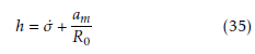 The right hand side of the Eq. (35) contains the differential term of the LOS rate which is a measured variable. Using the derivative of the measured variable (or estimated value) may cause numerical problem since the differentiation is sensitive to measurement noise and to the characteristics of state estimator. Thus, using the derivative of the LOS rate should be avoided.
Similar to [18] and [15], assuming that a UDT h is the input to some strictly proper virtual filter G(s), and setting its output denoted by hˆ as the estimate of h, lead to the following representation in the Laplace
domain form as
![]() In fact, it is impossible to extract h(t) as a signal. In this paper, we merely assume that it is the input to the virtual filter for the sake of developing the UDT estimator. Although various kinds of filters can be the candidates
In fact, it is impossible to extract h(t) as a signal. In this paper, we merely assume that it is the input to the virtual filter for the sake of developing the UDT estimator. Although various kinds of filters can be the candidates
for the virtual filter, the following first-order-lag filter is applied in order to facilitate the design.
 where τ indicates the time constant and that is a design parameter to be tuned. The time constant τ characterizes the convergence rate. By using the first-order-lag filter shown in Eq. (37), Eq. (36) is expressed in the time domain form as follows:
![]() where we assume hˆ(0) = 0 without loss of generality. Substitute the left hand side of Eq. (38) for the left hand side of Eq. (35) and rearrange it to derive
where we assume hˆ(0) = 0 without loss of generality. Substitute the left hand side of Eq. (38) for the left hand side of Eq. (35) and rearrange it to derive
 After integration of Eq. (39) with intervals [0,t] and solving for hˆ, the following estimator can be obtained.
 The estimator, denoted by Eqs. (40) and (41) is consisted only of the measurable LOS rate, the lateral acceleration of missile and the design parameter. Therefore, if the LOS rate is measurable, the UDT estimator is designed using one design parameter τ.
The convergence rate of the UDT can be enhanced by decreasing the design parameter τ. However, in practically, it has minimum limitation to attenuate the influence of noise. Since Zhong [17] explains the convergence property of the estimate, it is omitted in this paper.
2.5. Stability of the Uncertainty and Disturbance Term
In this section, we explain about the convergence of the uncertainty and disturbance estimator. It is assumed that the UDT (h) is continuous (the time differentiation of h is bounded). Estimated error is defined as
![]() Considering the following non-negative-definite function.
Considering the following non-negative-definite function.
 and performing the time derivative of Eq. (43) yields
![]() Substituting Eq. (13) into Eq. (39) provides
Substituting Eq. (13) into Eq. (39) provides
![]() Then, the differentiation with time of Eq. (42) derives
Then, the differentiation with time of Eq. (42) derives
 Substituting Eq. (46) for Eq. (45) leads to
![]()
![]() where h˙ is assumed to be bounded, considering |h˙| ≤ C
where h˙ is assumed to be bounded, considering |h˙| ≤ C
(C: the positive constant), V˙h < 0 is guaranteed when
|h˜| > τ|h˙| and the estimation error with elapse of time (t→∞) is ultimately bounded within the range of
![]() It can be seen from Eq. (49) that the estimation error can be reduced by decreasing τ. Furthermore, when the UDT is constant, that is h˙ = 0, the uncertainty and disturbance term h is estimated without error (hˆ→h).
It can be seen from Eq. (49) that the estimation error can be reduced by decreasing τ. Furthermore, when the UDT is constant, that is h˙ = 0, the uncertainty and disturbance term h is estimated without error (hˆ→h).
2.6. Discussion of uncertainty and disturbance-compensated intercept guidance with LOS rate measurements
From the UDT estimator of Eqs. (40) ∼ (41) and the guidance command of Eq. (35), the proposed UDT is summarized as follows:
ω˙ = −hˆ + am,ω(0) = 0,hˆ(0) = 0 R0 hˆ = (σ − σ (0)+ω)/τ
am = R0(kσ +hˆ)
When the lateral acceleration command value is not limited and there is no time-lag in the guidance system, the lateral acceleration in Eq. (41) equals to the desired lateral acceleration of Eq. (17) as described in the preceding equation. In this case, Eq. (17) is substituted into Eq. (41) with am = amd then one obtain
![]() As shown above, the UDT estimator proposed by the authors is almost equivalent to the one composed only proportional-integral filter of the LOS rate, and the design parameters k, R0 and τ. That is, in comparison with the existing guidance laws demanding extra information such as the closing velocity, the LOS range, the time-to-go and the lateral acceleration of target, the proposed guidance law using only the LOS rate is useful from the view point of implementation simplicity.
As shown above, the UDT estimator proposed by the authors is almost equivalent to the one composed only proportional-integral filter of the LOS rate, and the design parameters k, R0 and τ. That is, in comparison with the existing guidance laws demanding extra information such as the closing velocity, the LOS range, the time-to-go and the lateral acceleration of target, the proposed guidance law using only the LOS rate is useful from the view point of implementation simplicity.
3. Simulation
Guidance simulations have been performed to confirm the effectiveness of the proposed guidance law. When the missile velocity is sufficiently larger than the target velocity, there is no significant difference between the proposed guidance law and PN guidance law. Therefore, this paper presents an example case; the target velocity is larger than the missile velocity where the performance difference appears noticeably by using the proposed guidance law. In the simulations, the equations of motion Eqs. (1) ∼ (7) are used. The setting values of initial states and design parameters are summarized in the Table 1.
The limitation load of the missile is set to forty times of the gravitational acceleration (G), that is, 40G. When the commanded lateral acceleration exceeds the limit, the limited value is used as a command in the simulation. The target acceleration set as 4G to be constant. For comparison purposes, the PPN guidance law using the missile velocity in Eq. (25); the TPN guidance law using the closing velocity in Eq. (26); the APN guidance law adding the extra term which considered the maneuvering target in Eq. (27); and the OG of using tgo information in Eq. (33) are compared by the proposed guidance law in the simulations.
Table 1: Initial kinematics and design parameters
| Parameters | Values | |
| Vm | 1,500 | [m/s] |
| xm | 0 | [m] |
| ym | 0 | [m] |
| γm | 20 | [deg] |
| max{am} | 40G | [m/s2] |
| m | 100 | [kg] |
| min{m} | 60 | [kg] |
| S | 0.01267 | [m2] |
| Isp | 300 | [s] |
| G | 9.806 | [m/s2] |
| Vt | 3,500 | [m/s] |
| xt | 55,000 | [m] |
| yt | 9,000 | [m] |
| γt | -175 | [deg] |
| at | 4G | [m/s2] |
| k | NVm0/R0 | [1/s] |
| N | 3 | [−] |
| N0 (TPN, APN) | 3 | [−] |
| τ | 0.3 | [s] |
| τ1 | 0.5 | [s] |
| R0 | R(0) | [m] |
The simulations with such comparative guidance laws are made because the simulation setting of guidance laws with the effective navigation constant of N0 = 3 in TPN and APN provide optimal solution in the sense that the square integral of lateral acceleration becomes minimum when there is no system response delay. The proposed guidance law assumes that only LOS rate information is used, whereas the TPN, APN and OG guidance laws use the closing velocity that cannot be used in this assumption. Hence, simulation results PPN using the missile velocity are also shown as for another comparison guidance law with the same measurement condition. When simulations are performed for TPN, APN and OG guidance law, information on the closing velocity and the target lateral acceleration can be used without error.
Table 2: Resulting miss distance is shown. For comparison, we also show the results when Vm is constant, that is, when the affect of the axial acceleration by the thrust or of the deceleration due to the aerodynamic drag is not considered.
| guidance method | miss distance [m] | |
| Vm=const. | Vm changes | |
| Proposed | < δ | < δ |
| PPN | 565.76 | 813.19 |
| TPN | 0.18 | 8.43 |
| APN | 0.0028 | 0.02 |
| OG | < δ | 0.0096 |
The flight trajectories of the missile and the target are shown in Fig.2. The red solid line drawn from the upper right to the lower left is the trajectory of the target, the red broken line denotes the missile trajectory with the PPN guidance law, the green broken dotted line is made with the TPN guidance law, the magenta dotted line is made with the APN guidance law, the red broken line is made with the OG law, and the blue solid line is made with the proposed guidance law. The resulting miss distance value using each guidance law is shown in Table 2. For comparison purpose, the results of the case where the missile velocity is constant is also shown. In this case, when the miss distance is 0.001[m] or less, it is expressed as ”< δ”. From enlarged view of the lower right of Fig. 2
(the equivalent aspect ratio), it is observed that the trajectories with the APN, OG and proposed guidance laws have similar trajectories. Simultaneously, we can see that the APN, OG and the proposed guidance law approach to the target in a shape close to a straight line, but the PPN and TPN guidance law draws a curve towards the target. It is considered that this causes large miss distance values as shown in Table 2. Additionally, for the case where the missile velocity changes with time, the miss distance values of the PPN, TPN, APN and OG guidance law become large, whereas the proposed guidance law keeps in the same level. Note that the trajectory with the proposed guidance law is almost similar to the trajectories with the APN guidance law and OG law using the closing velocity and the lateral acceleration, and the miss distance value is smaller than the other guidance laws.
The curvature of the missile trajectory in Fig. 2 becomes clear by observing the histories of the lateral acceleration applied to the missile. Figure 3 shows the time history of the missile’s lateral acceleration (socalled latex) when using the each guidance law as well as the time history of the LOS rate in Fig. 4. In Fig. 3, the value of lateral accelerations of the APN guidance and OG laws converge to almost zero with exception at the time of intercept. In the proposed guidance law, since the target lateral acceleration is considered as a part of the UDT, it turned out that the missile lateral acceleration tends to converge to a value close to the target lateral acceleration at 4G. In addition, it can be seen from Fig. 3 that the PPN and TPN guidance laws have reached the limited value of 40G before the intercept. The PPN guidance law is considered to generate a large miss distance value as shown in Table 2 because it reached this limit earlier than that of the TPN guidance law. It can also be observed from Fig. 4, since the LOS rate with the proposed guidance law converges to a value close to zero at the impact time, a small miss distance value shown in Table 2 was obtained. Consequently, under the condition shown in Table 1, that is, when the target velocity is larger than the missile velocity, the proposed guidance law is considered to exhibit desirable performance.
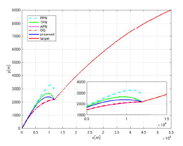 Figure 2: Flight trajectories of the missile and the target. The lower right is an enlarged view.
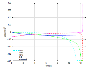 Figure 3: The time history of the missile’s lateral acceleration in each guidance law is shown. The limitation load factor of the missile is set 40G this is forty times of the gravitational acceleration.
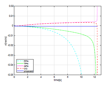 Figure 4: LOS rate vs time is shown. It is desirable for the LOS rate to be zero.
Figure 5 and 6 shows the time histories of the missile velocity and the missile mass. In this simulation, since the minimum value of the missile mass is limited to 60[kg], the missile intercepted the target before reaching that value.
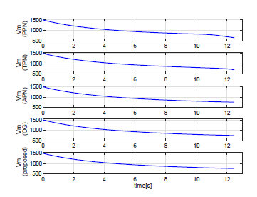 Figure 5: The missile velocity of each guidance considering axial acceleration by the thrust force, and deceleration due to aerodynamic drag vs time.
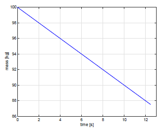 Figure 6: Mass of missile decreasing with time.
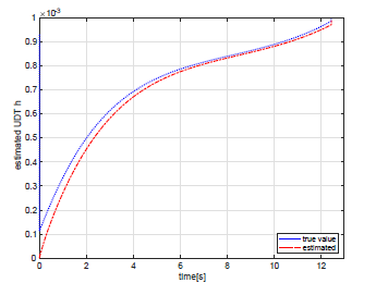 Figure 7: The time history of the estimated UDT h and the true value.
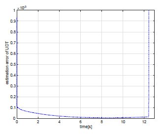 Figure 8: UDT error vs time.
This figure shows (true) − (estimate) values in Fig.7.
Finally, to demonstrate the performance of the UDT estimator, the time history of the UDT h which is a true value and that of estimated value hˆ are shown in Fig. 7, in addition, the time history of the estimation error is also shown in Fig. 8. From these figures, it can be seen that the estimator using the time constant of τ = 0.3[s] can be estimated so that the estimated value approaches the true value about 2 to 6 seconds. By reducing the value of the time constant τ, it can be expected to increase the convergence rate to the true value, but the response of the lateral acceleration tends to fluctuate. Therefore, the time constant is too small is not desirable. The reason that the estimation error increases at the intercept time in Figs. 7 and 8 is that numerical divergence occurs for the real system where the distance R in Eq. (14) converges to zero while the acceleration converges to the target acceleration that are none zero value. Therefore, the proposed guidance law should be deactivated or hebetated at the end of the interception to obtain better performance. This is the future work for this study since the LOS range is not measured. Regardless of the difficulties, the resulting miss distance as shown in Table 1 demonstrates the excellent performance of the proposed guidance law.
4. Conclusions
A new guidance law for missile-target engagement using information of LOS rate only is developed. From the simulation study, the proposed guidance law exhibits excellent performance almost equal to the OG law where the OG law uses additional information of the LOS range, the closing velocity and the lateral acceleration of the target, whereas the proposed guidance law uses only LOS rate information even if uncertain modeled dynamics such as velocity change and directional error is included. Hence, even with a guidance system that cannot measure the closing velocity or maneuvering target, we can anticipate that almost the same performance as that of conventional excellent guidance with using the closing velocity or target maneuver can be obtained by using the proposed guidance law.
For future works, we will apply the proposed guidance against various targets or initial settings, study a blind sight determination method (or deactivation technique in the proximity of the target), and investigate the influence of the time-lag constant changes and observation noise to the design parameters on guidance performance.
- R.E. Machol, W.P. Tanner.Jr, and S.N. Alexander, System Engineering Handbook, Chap.19 Guidance, R.E. Hill, 1965.
- Y. Yavin, R.De. Villiers, Proportional navigation and the game of two cars: the case of a pursuer with variable speed, Computers & Mathematics with Applications, Vol.18, No.1-3, pp.69- 76, 1986.
- M.J. Tahk, C.S. Park, and C.K. Ryoo , Line-of-Sight Guidance Laws for Formation Flight, Journal of Guidance, Control, and Dynamics, Vol.28, No.4, pp.708-716, 2005.
- Y. Sato, T. Yamasaki, et al., Trajectory Guidance and Control for a Small UAV, International Journal of Aeronautical and Space Sciences, Vol.7, No.2, pp.137-144, 2006.
- M. Matsuda, H. Takano, T. Yamasaki and I. Yamaguchi, A Note on the Optimal Spacecraft Guidance, APISAT, 7.4.1.pdf, 2012.
- P.J. Yuan and S.C. Hsu, Rendezvous Guidance with Proportional Navigation, Journal of Guidance, Control, and Dynamics, Vol.17, No.2Cpp.409-411, 1994.
- C.D. Yang, C.C. Yang, A Unified Approach to Proportional Navigation, Transactions on aerospace and electronic system, IEEE, Vol.33, No.2, pp.557-567, April 1997.
- P. Zarchan, Tactical and Strategic Missile Guidance, Sixth Edition, AIAA, ch.8, pp.163-185, 2007.
- P. Zipfel, Modeling and Simulation of Aerospace Vehicle Dynamics, Second Edition, AIAA, 2007.
- T. Kuroda, and F. Imado, Advanced Missile Guidance System against a Very High Speed Maneuvering Target, Proceedings of AIAA Guidance, Navigation and Control Conference, pp.3445, 1989.
- A.E. Bryson, Jr., and Y.C. Ho, Applied Optimal Control, – Optimization, Estimation, and Control-, Hemisphere Publishing Corporation, New York, pp.154-155, 1975.
- Y. Baba, K. Inoue, and R.M. HOWE, Suboptimal guidance with line-of- sight rate only measurements, Proceedings of AIAA Guidance, Navigation and Control Conference, AIAA 88-4066-CP, Minneapolis, pp.122-129, 1988.
- S. Nakagawa, T. Yamasaki, H. Takano, and I. Yamaguchi, Disturbance- Compensated Intercept Guidance Using Line-of- Sight Rate Information, 11th Asian Control Conference, IEEE, pp.388-393, December 2017.
- S. Nakagawa, T. Yamasaki, H. Takano, and I. Yamaguchi, Comparison study on Disturbance-Compensated Intercept Guidance Using Line-of-Sight Rate Information against Optimal Guidance, Multi-Symposium on Control System, 2018.
- T. Yamasaki, S.N. Balakrishnan, and H. Takano, Sliding modebased intercept guidance with uncertainty and disturbance compensation, Journal of Franklin Institute, Vol. 352(11), pp. 5145-5172, 2015.
- C.D. Yang, and C.C. Yang, A Unified Approach to Proportional Navigation, IEEE , Transactions on aerospace and electronic system, Vol.33, No.2, pp.557-567, April 1997.
- Q.C. Zhong, Comments on gA time delay controller for systems with Uncertain Dynamicsh, 27th January 2013.
- S.B. Phadke, and S.E. Talole, Sliding Mode and Inertial Delay Control Based Missile Guidance, IEEE Transactions on Aerospace and Electronic Systems, Vol.48(4), pp.3331-3346, 2012.
- K. Youcef-Toumi, and O. Ito, Controller design for systems with unknown nonlinear dynamics, Proceedings of the American Control Conference, Minneapolis, pp.836-845, 1987.
- K. Youcef-Toumi, and O. Ito, A time delay controller for systems with unknown dynamics, Journal of Dynamic System, Measurement, and Control, – Transactions of the ASME, Vol.112(1), pp.133-142, 1990.