Closed Approach of a Decoder Mobile for the 406 Mhz Distress Beacon

Adv. Sci. Technol. Eng. Syst. J. 3(6), 243–246 (2018);
 DOI: 10.25046/aj030631
This article presents the design and realization of decoder mobile for distress beacon 406 MHz. The use of the sparse Fourier transforms in the processing of distress beacon signals. The characteristics of these decoders are mobility, able to decode all the frequencies of the beacons. It locates with great precision the location of the emitting emergency beacon, which is equipped with GPS, indicates the actual distance from which the alerts emanate. This compressed detection can give us a more detailed form of signals, so new results are given in the detection, the performance of the results is presented through experience.
1. Introduction
Canada, France, the Soviet Union and the United States are the first countries to sponsor the COSPAS SARSAT system at its inception which is a permanent international humanitarian satellite search and rescue system, detecting and locating beacons of emergency installed in ships, aircraft, and individuals. The program was subsequently joined by many other countries today (total forty countries and two organizations in 2016) [1] [2]. Regarding distress in the three cases cited, the finding the position of the disaster, and the necessary time of rescue and effectiveness depend on the reliability of the communication between the LUTs and the satellites [3] [4]. In order to provide semi-realistic alerts and location information from GEOSAR, the second-generation 406 MHz beacon is used to allow the location data to be encoded in the transmitted 406 MHz message [5]. The importance of this research is to reduce the time spent in research during the rescue process through the use of decoding screens, which in turn contain information inside the frame (GPS coordinates and the distance between the mobile decoder and markup), which enables us to identify the location and the implementation of the rescue process quickly.
2. Cospas Sarsat Concept
Figure1 presents a basic structure of the COSPAS SARSAT system [1] [2]. In the most disasters cases, the emergency beacons are activated when human lives are threatened. These alerts are received by the satellites and are retransmitted to the terrestrial stations distributed throughout the world “Local User Terminals” (LUT). Alerts are routed to the country’s Mission Control Center (MCC), which operates the satellite terrestrial stations from which LUT is located. Routing alerts include the location of the calculated beacon to the LUT received by one of the orbiting low-Earth (LEO) satellites.
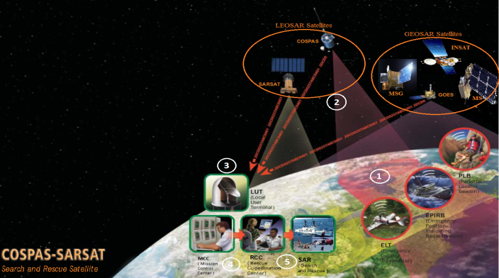 Figure 1. COSPAS SARSAT system [1]
The rescue operation is a carefully coordinated phase. Initially, the alerts are verified (based on the Doppler effect) after the confirmation the information is sent according to the country of the registration or to any rescue coordination center (RCC), which is equipped with emergency search and rescue correspondence [1] [2]. SAR satellites can also receive low distress signals from beacons.
After 2009, all beacons transmit on 406 MHz [6]. The universe is so complicated; the human being is always thirsty for discoveries enabling him to discover it, which exposes him to a danger, which has led through research and practice, the creation and realization of three types of emergency beacons currently in service [1] [2]:
- Personal Locator Beacons (PLBs) for individuals,
- Emergency Position Indicating Radio Beacons (EPIRBs) for maritime applications, and
- Emergency Locator Transmitters (ELTs) for aviation applications.
3. Frequency beacons cospas-sarsat 406 mhz
In January 2010, the 406.040 MHz frequency began to be used. Where the principles frequencies are 406.049 MHz and 406.052 MHz [6].
Where, the band 4 0 6.0 – 4 0 6.1 MHz has been set aside by the International Telecommunication Union ( ITU) for the low power satellite emergency position Currently, Cospas Sarsat distress beacons transmit to 406.025,406.028, 406.037, and 406.040 MHz.
4. Specification and Design
4.1. Specification
Specification of the second Generation 406 MHz SAR beacon and specification of ELT is defined in COSPAS-SARSAT technical document [5] [7].
4.2. Functional block diagram of decoder
Figure 2 shows the Mechanism functioning of a 406 MHz decoder. The main objective of the decoder is to identify the system, which that retransmits, determine when the reception took place, and then retransmit it again. The information to retransmit the weft shall be received as well as the temporal information. All the information’s are displayed on one single screen with 4 lines of 20 characters. To do all this, the information is intensified.
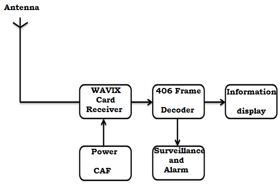 Figure 2. Functional schema of a 406 MHz decoder
5. Implementation of the Decoder
Figure 3 and 4 presents the Frame Decoder and complete system respectively. These two figures show: on the left side the jack 2.5 mm for the GPS connection, one on-off switch in the middle and the power jack which also serves as the battery charge point, and the jack 3.5 mm to connect the output receiver on the frequency of the beacon.
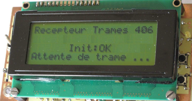 Figure 3. Frame decoder with display homepage.
On the right side, LED is used to monitor the operation and two push buttons allow navigating in memory (Figure 9). Since the system permanently records new message data, it is preferable to disconnect the entry when you want to see the pages in memory.
The complete mobile decoder after improvement of the old decoder. The system “receiver decoder” is now operational tobe with the permanent listening of the beacons of distress is shown in Figure 4 [10]. Its sensitivity is very good. As soon as a beacon passes in emission, whatever its frequency, the receiver is fixed automatically on the real frequency of the beacon and the decoder displays the contained information in the screen. The sound of the buzzer is then made hear during one second.
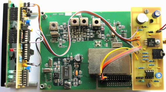 Figure 4. The complete system for receiving and listening to 406 MHz beacons
6. Experiment Results
6.1. Performance of the ELT Beacon
The 406.040 MHz ELT beacon signal is experiment results. The frequency meter and Spectrum Analyzer indicates the frequency is 406.040 MHz [10], it has the same spectrum of an EPIRB Beacon [11].
6.2. Position of the Beacon
Figure 5 corresponds to GPS position transmitted by the beacon. The frame is containing the position displayed on the fourth line. Where, all information is present except the time of receipt.
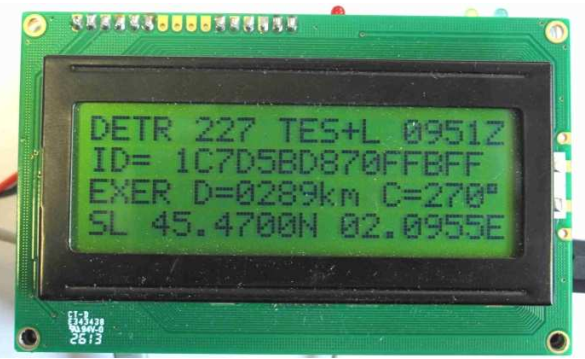 Figure 5. The GPS position transmitted by the beacon
The experience of the GPS receiver. Figure 6 shows Longitude Est. 02.09550 and North Latitude 45.47000 shows position in Google Earth. This indicates the point indicated in the figure this experiment was carried out.
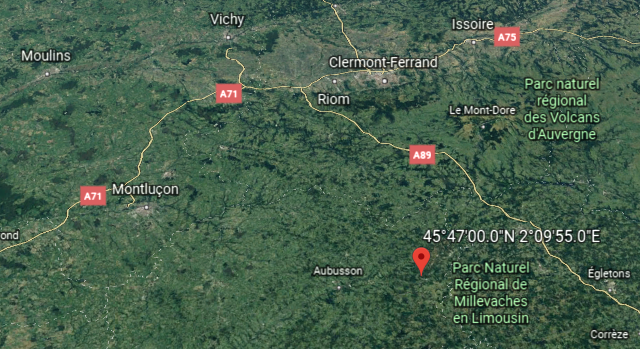 Figure 6. Position Plot in Google Earth
6.3. Functioning of frame decoder
Output of the receiver listening to the beacon
The signals emitted by the beacon are a series of peaks, alternately positive and negative. These peaks are 1.25 ms or 2.5 ms. they correspond to the phase jumps of the PSK modulation as shown in Figure 7 and Figure 8 . In fact these peaks crossepond to the rising brows and the descending brows of the crenels that control the PSK modulator.
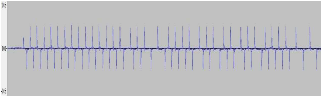 Figure 7. The frames emitted by the beacon
Figure 8 shows the signals at the output emitted by the Beacon; the frame information is more scope by battlements but by peaks. With this type of output by peaks, the frame generator performs an excellent simulation of the chain “Beacon 406 + receiver”
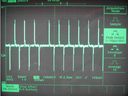 Figure 8. The signals at the output in the form of alternating peaks
Display of the distance between mobile decoder and the beacon
The calculation and display of the distance are fully automatic. As soon as the decoder knows its position and that of the beacon, it displays the distance and heading in place of the identification of the beacon on the second part of the third line. Figure 9, and 10 shows the distance display: it is 10:09 Local time, and heard beacon is a 49.9 Km north west.
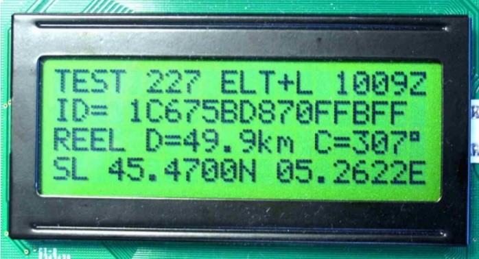 Figure 9. Display of distance and heading
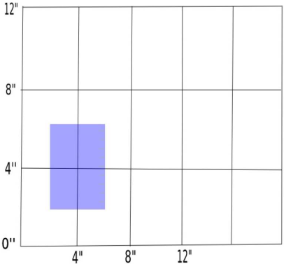 Figure 10. The position of the beacon is discretized at no 4 arc seconds, which leads to a position of uncertainty 123 m North and 87 m East
7. Conclusion
This work concerns the disaster beacon, even at great distances, and when the signals are weak, it is quite easy to recognize the signal of the 406 MHz beacon in the noise.
By coupling the receiver with a 406 MHz fram decoder, a beacon receiving station is obtained, which can operate as a permanent listener, and it will automatically decode the transmitted frame, so that our receiver-decoder is operational to be permanently listened to The reception of a signal on any frequency, the receiver automatically stabilizes on the frequency of the beacon and our decoder displays the information contained in the frame (GPS coordinates and distance between Mobile decoder and beacon), which will allow us to quickly locate the place, and facilitate the intervention of rescues, consequently, reduce the search time. According the new development in monitoring beacon as showing by [13], we can expect more interesting results in the using of disaster beacon.
- http://www.cospas-sarsat.org, 30.05.2018.
- http://www.sarsat.noaa.gov, 30.05.2018.
- C. W. Scales and R. Swanson, “Air and Sea Rescue via Satellite Systems”, IEEE Spectrum (ISSN 0018 – 9235), vol 21, pp. 48–52, March 1984. https://doi.org/10.1109/MSPEC.1984.6370206
- I. W. Taylor and M. O. Vigneault, “A neural network application to search and rescue satellite aided tracking (SARSAT), In Proceedings of the Symposium”, Workshop on Applications of Experts Systems in DND, pp. 189-201, Royal Military Coll. Of Canada, 1992.
- J. V. King ‘‘ New Developments in the COSPAS-SARSAT Satellite System for Search and Rescue’’, 55th International Astronautical Congress 2004 https://doi.org/10.2514/6.IAC-04-M.4.07
- Specification for COSPAS – SARSAT 406 MHz Distress Beacons, C/S T.001 Issue 3 – Revision14, October 2013
- COSPAS-SARSAT 406 MHz Frequency Management Plan, C/S T.012Issue 1 – Revision 9, October 2013.
- COSPAS-SARSAT 406 MHz Distress Beacon Type Approval Standard, C/S T.007 Issue 4 –Revision8, October 2013.
- COSPAS-SARSAT Guidelines on 406 MHz Beacon Coding, Registration and Type Approval, C/S G.005, Issue 2 – Revision 5, October 2010.
- B ALI SRIHEN, J.P Yonnet, and M BENSLAMA, ‘‘Design and realization an ELT beacon and decoders of frames 406 MHz’’. International Conference (IEEE) on Engineering & MIS (ICEMIS), 8-10 May 2017, Monastir, Tunisia https://doi.org/10.1109/ICEMIS.2017.8272967
- I. Joo, J.H. Lee, Y.M. Lee, C.S. Sin, S.U Lee, and J Kim, ‘‘Development and Performance Analysis of The Second Generation 406 MHz EPIRB ’’ International Conference (IEEE) 4th Advanced Satellite Mobile Systems, 26-28 Aug. 2008, Bologna, Italy https://doi.org/10.1109/ASMS.2008.64
- S. STATLER ‘‘ Beacon technologies’’ Apress 2016; p 21; p 82; San Diego; California, USA