An Improved Cross-Connection Abatement Algorithm with RSSI Using In-Band Magnetic Field Control in Densely Located LC Wireless Charger Environments

Adv. Sci. Technol. Eng. Syst. J. 3(6), 247–251 (2018);
 DOI: 10.25046/aj030632
In densely located loosely coupled wireless charger environments, cross-connection errors can occur when wireless chargers operate at the same time within the same wireless communication range. In this work, an effective algorithm is proposed to prevent cross-connection error. The algorithm based on the cross-connection abatement technique with the received signal strength indicator of out-band BLE communication has improved using an in-band magnetic field signal controlled by a pulse-width-modulation-like waveform. The experimental results obtained from a proper test set in a RF shield room verify that the wireless charging system using the proposed algorithm provides wireless charging services without cross-connection errors.
1. Introduction
At present, loosely-coupled (LC) wireless chargers are employed to support the simultaneous charging of a multiplicity of devices, such as laptops, tablets, and mobile phones in multiple wireless charging pads (power transmitting units: PTUs) and charging devices (power receiving units: PRUs) [1-3]. In densely located LC wireless charger environments, cross-connection errors can occur when PTUs and PRUs operate simultaneously in the same wireless communication range. The cross-connection errors are a kind of the control error between the main PTUs and neighboring PRUs due to the interconnection of the PTU/PRU communication. Figure 1 shows the concept of the cross-connection errors. When two (or more) PTUs with their own PRU are disposed closely together and operate at the same time, a control error may occur as one PTU’s communication connects to the other PRU. If the PTU recognizes the battery information of the other PRU, over-power or low-power transmission can occur which may damage the PTU or prevent charging. In other words, the cross-connection error may cause the over-power or low-power transfer that may damage the PTU and PRU. In [4], we proposed an effective algorithm that focuses on the measured value of the received signal strength indicator (RSSI) to avoid cross-connection error. The RSSI, however, is heavily affected by nearby objects and by environments regardless of distance [5]; i.e., an RSSI signal tends to fluctuate due to many external factors, such as obstacles, multipath fading, interference diffraction, and absorption. Moreover, when the distances between PTUs are small, it is difficult for a PTU to distinguish its own PRU from the others via only comparison of the RSSI values because the RSSI values become similar. Therefore, the algorithm using only the RSSI signals is not able to prevent communication connection errors in very dense environments.
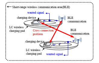 Figure 1. Conceptual diagram of the cross-connection errors between the charging devices and the wireless charging pads within the short-range wireless communication area.
In this work, we propose an effective algorithm to solve the RSSI problems mentioned above. The proposed cross-connection abatement (CCA) algorithm is based on the CCA technique with the RSSI of out-band (2.4-GHz BLE) communication improved using the controlled magnetic field signal of in-band (6.78 MHz) power transmission. The CCA technique uses the out-band RSSI and in-band magnetic field signals progressively to enable the wireless chargers (PTUs) to be used in all dense environment without cross-connection errors. The PTU first finds the PRUs that are close to each other using the RSSI, then finds its own PRUs using the magnetic field signal controlled by the output power of the power amplifier. The PTU uses a waveform-controlled magnetic field signal, such as a pulse width modulation (PWM) signal, as a second signal to sense its PRU. To validate the performance of the proposed CCA algorithm, a test set was built in a dense charger environments.
2. System Description and Experimental Results
A test set was fabricated in a dense, loosely coupled (LC) measuring environment in a radio frequency shielded chamber with a 6.38 (length) m × 5.48 (width) m × 3.75 (height) m dimension [4]. The test set was composed of 10 wireless charging pads, 10 smartphones, a 16-V power on-off control switch, and a personal computer. The wireless charging pad with an area of 20 cm × 30 cm act as a PTU and the smartphone with a built-in wireless charging module acts as a PRU. The wireless charging pad that operates at 6.78 MHz with a 2.4-GHz Bluetooth low energy used to establish between PTUs and PRUs communication. The graphical user interface (GUI) monitors Bluetooth low energy RSSI values of all PRUs.
Figure 2 shows block diagrams of a PTU and PRU system used in the test set in a dense wireless-charger environment (two chargers within a 10-cm distance) and their output voltage waveforms as applied to the proposed CCA alorithm. The PRU is composed of a rectifier, a DC/DC converter, and a monitering circuit block. The rectifier converts received AC power signal to DC voltage. The DC/DC converter converts a received low voltage to a high voltage and the monitering block checks the charging conditions. The PTU is composed of a power amplifier, a buck converter, a wireless power on/off control switch, and a microprocessor. The power amplifier produces a 6.78-MHz RF power and the buck converter controls the output power, which produces a PWM-like waveform. For the PTU and PRU communication, a 2.4-GHz BLE was used. In [6], we proposed an effective CCA technique. The working sequence of the proposed technique is as follows.
To recognize the presence of a PRU in the PTU charging area, the wake-up power signal is transmitted over a regular cycle to sense the load. Once the advertisement signal is received, before the charging device is registered, an RSSI threshold level is identified to ensure that the PRU exists in the charging area. The RSSI threshold is measured as the position of the PRU in the PTU’s charging area changes. The RSSI threshold level can be selected to be 3 dB (for noise margin) less than the minimum value of the highest RSSI level (for example, -12 dBm in [4]) among the received RSSI of PRUs. Once the threshold level is determined, PRUs with a value lower than that threshold is considered to have the cross-connection error. When this happens, the PTU turns off the wireless power for 100ms and returns to the load detection phase for a normal reconnection. The PRU with the RSSI threshold level registers its ID to initiate the wireless charging service. Then, the PTU monitors the load detection and advertisement signal of the PRUs in order to detect PRUs added or removed in real time during the wireless charging process.
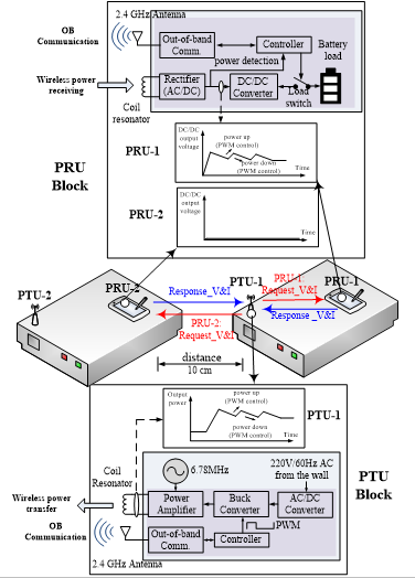 Figure 2. Block diagrams of a PTU and PRU sysytem used in the test set and schematic output voltage plots measured from PTU-1 and PRU-1, 2. PRU-1 belongs to the PTU-1, whereas PRU-2 is cross connected.
As the distance between two wireless charging pads (PTUs) decreases (less than 10 cm as shown in Figure 2), it becomes difficult for the PTU to distinguish its own PRU from the other one merely by comparing the RSSI values. This is because the received RSSI values of two PRUs eventually become similar to each other at the threshold level. For PRUs with RSSI values below the threshold, the communication connection is not made because the PTU identifies them on different charging pads. However, if the RSSI values of PRUs may be greater than or equal to the threshold, these PRUs should be revalidated for the cross-connection status. In that case, the PTU uses the magnetic field control of the transmit power signal to reaffirm the cross-connection status. A change in the magnetic field strength on the resonator of the PTU induced by varying the input current supplied from the power amplifier results in the change of the power information received by PRUs. The PTU sends a magnetic field signal controlled by a waveform, such as a PWM-like waveform, which increases or decreases the output power of the power amplifier. This signal is then compared with the power change information received by the PRUs. If the power variation pattern is different from the PWM-like variation pattern, the cross-connection is confirmed.
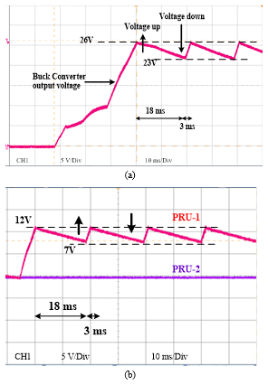 Figure 3. Measured voltage waveforms of the PTU and the PRUs shown in Fig. 2. (a) Output voltage waveform of the power amplifier in PTU-1 (inset in Fig. 2). (b) Received voltage waveform at PRU-1 and PRU-2 (inset in Fig. 2).
Figure 3 shows the voltage waveforms measured at PTU-1, PRU-1, and PRU-2. Figure 3 (a) shows the output voltage measured at the Buck converter of PTU-1 which induced the magnetic field signal controlled by a waveform like PWM. Figure 3 (b) shows those at DC/DC converters of PRU-1 and PRU-2. In Figure 3 (a), the output voltage of the power amplifier varies from 23 V to 26 V with a 21-ms period. The rise time is 3 ms and the fall time is 18 ms. As shown in Figure 3 (b), the voltage change from 7V to 12V is repeatedly measured in PRU-1, which has a 21-ms period with a 3-ms rise time and 18-ms fall time. On the other hands the PRU-2 does not exhibit the voltage change. The measured results indicate that PRU-1 is a self-charging device of PTU-1, while PRU-2 belongs to another pad.
After PTU-1 identifies that PRU-2 is not its own PRU, PTU-1 disconnects communication with PRU-2 and connects to PRU-1 again to start the charging process. As a result, it is possible to accurately detect the occurrence of the cross-connection error by comparing the change in the intensity of the magnetic field of the PTU and the power change pattern received in the PRU.
Table 1 shows a comparison of the effectiveness of cross-connection abatement algorithms on the distance between PTUs. When the distance between PTUs is relatively long (longer than 15 cm), both techniques are very effective. As the distance is short (shorter than 10 cm), the CCA algorithm with RSSI and modulated magnetic field signal is still effective, while the CCA algorithm with only RSSI signal is not effective because the PTU does not recognize its own PRU.
Table 1. The comparison of effectiveness of cross-connection abatement algorithms on the distance between PTUs.
| Long distance between PTUs | Short distance between PTUs | Ref | |
| CCA algorithm with only RSSI signal | effective | not effective | [4] |
| CCA algorithm with RSSI & modulated magnetic signals | effective | effective | This work |
3. Improved Algorithm Description
Figure 4 shows the process flow of the proposed CCA algorithm with the RSSI and the controlled magnetic field signals. As shown in the figure, the left line (PTU) shows the command frames and the power levels (dark areas) of the PTU, and the center line (cross-connected PRU) and right line (own PRU) show the response and report frames, respectively, according to the request of the PTU. This process flow operates in four states: a load detection state, cross-connection prevention state, registration state, and charging state. The basic operation sequence of the CCA algorithm is as follows.
In the load detection state, the wake-up power supplies 5 V to the PA for 500 ms (tBEACON) for every 3 sec (tBEACON_PERIOD) cycle. The wake-up power is the minimum power level necessary to activate the micro control unit (MCU) of the PRUs to establish the communication. When a PRU is detected, the MCU of the PTU increases the voltage supply at the PA to 7 V to supply sufficient power for the PRU communication and the stable operation of the MCU. The woken-up PRUs proceed to the next stage, namely, the cross-connection prevention state. After the load detection between the PTU and PRUs, the PTU transmits a “request RSSI” frame to the PRUs in order to verify the state of cross connection. Upon receipt of the “request RSSI” frame, the woken-up PRUs immediately transmit their RSSI values to the PTU. By comparing the RSSI values with the threshold value (−15 dBm in [4]), the PTU first recognizes those PRUs as the possible PRUs that have greater RSSI values than the threshold value, before proceeding to accurately judge them as its own PRUs. In the case of PRUs that have lower RSSI values than the threshold value, no communication connection is made because the PTU recognizes them as belonging to other charging pads (PTUs). The PRUs that have higher RSSI values than the threshold value should be rechecked for the state of cross connection because RSSI values can become greater than the threshold value when the distance between the charging pads decreases. The PTU rechecks the state of cross-connection using the magnetic field control of the transmitting power signal. The change in the magnetic field strength on a resonator of the PTU, induced by changing the input current supplied from a PA, changes the power (voltage and current, V&I) received by the PRUs. The power (V&I) change information received by the PRUs is reported through the “report V&I” frames whenever the “request V&I” frames are transmitted during this state.
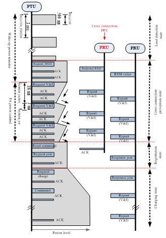 Figure 4. Sequence diagram of the proposed algorithm for cross-connection abatement.
The PTU causes an increase or decrease in the output power of the power amplifier and compares it with the power change information received by the PRUs. If these two power variation patterns are different, then a cross connection has occurred. In the algorithm, the magnetic field control is implemented for 18 ms (tPOWER_UP) for a power increase at the PA and for 3 ms (tPOWER_UP) for a power reduction at an interval of 21 ms. The control is carried out three times in a sequence. To detect the power change information (V&I) received by the PRUs based on the magnetic field control, the PTU transmits the relevant “request V&I” frames. Upon the receipt of the “request V&I” frames, the PRUs transmit the measured V&I information through the “report V&I” frames. The communication between the PTU and the PRUs occurs during the timespan of 21 ms of the power change. The three repetitions of the power-level change at the PTU and the power change information received by the PRUs are compared, and if the variation patterns turn out to be different or there are no changes in the received power, the PRUs start detecting places where cross-connection errors have occurred.
Consequently, the PTU transmits a reset command to the PRUs (such as the PRU-2) where cross-connections have occurred to disconnect the communication. The PRUs receive the reset command and switch to a standby state in order to receive the “request” frames from other PTUs. The PRUs (such as the PRU-1) that are verified to be its own proceed to the registration state.
After detecting the PRUs that are to be charged on its own pad in a cross-connection prevention state, the PTU sends a subscription request to its network and receives a session ID and the charging permit. The PTU then transmits the “request join” frames to its own PRUs. Consequently, the PRUs transmit the battery capacity information, which is necessary for charging, via the “response join” frames. By comparing the power capacity that the PTU can transmit and the battery capacity of the registered PRUs, the PTU decides whether the charging should be allowed. If the power transfer capacity exceeds, charging is not allowed, and the PRUs revert to the standby state. This information is notified to the PRUs through the acknowledgement (ACK) frames. After this registration state, the PTU proceeds to the charging state and starts a charging process. During the charging state, the PTU transmits the “charge start” commands to relevant PRUs to switch them to the charge state for charging the batteries. The PRUs switch on the load attached to the battery path and receive the power. The PTU monitors whether the power is delivered properly to the PRUs through the “report V&I” frames. Based on the power information received from PRUs, the PA adjusts its output power. The PTU sends back the “report” frames several times so that the power can be delivered stably to the PRUs. When the charging power is delivered to the PRUs, the voltage and current received by the battery are continuously monitored so that the required power can be controlled according to the charge mode. If the monitored voltage of the battery reaches a buffer voltage, the PTU judges that the charge has been completed. Thereupon, the PTU issues the “charge finish” commands to PRUs and switches the load connected to the battery to the off state, along with the transmission of an ACK command before displaying a buffer to the users through a user interface.
4. Conclusions
The proposed CCA algorithm has shown that cross-connection errors between wireless charging pads and charging devices in BLE wireless coverage can be prevented using simple RSSI threshold level detection and magnetic field control for power signal transmission. This approach can provide a reliable loosely coupled wireless charging service without an abrupt increasing in transmit power at the start of charging due to the gradual power-up pattern of the controlled magnetic field.
Acknowledgment
This work was supported by the Basic Science Research program through the National Research Foundation Korea funded by the Ministry of Education (NRF-2015R1D1A1A02061041) and by the Ministry of Science and ICT Korea under the ITRC (information technology research center) support program (IITP-2016-R2718-16-0012) supervised by the IITP (national IT industry promotion agency).
- J.J. Casanova, Z.N. Low, and J. Lin, “A loosely coupled planar wireless power system for multiple receivers,” IEEE Trans. Ind. Electron., vol. 56, no. 8, pp. 3060-3068, Aug. 2009. https://doi.org/10.1109/ TIE.2009.2023633
- R. Tseng, B. von Novak, S. Shevde, and A.K. Grajski, “Introduction to the alliance for wireless power loosely coupled wireless power transfer system specification, Version 1.0,” in 2013 IEEE WPT, May 2013, pp. 79-83. https://doi.org/10.1109/WPT.2013.6556887
- I. Yasar, L. Shi, K. Bai, X. Rong, Y. Liu, and X. Wang “Mobile phone mid-range wireless charger development via coupled magnetic resonance,” in 2016 IEEE ITEC, June 2016, pp.1–8. https://doi.org/ 10.1109/ITEC.2016.7520217
- N.Y. Kim, S.-W. Yoon, and C.-W. Kim, “Cross-connection abatement in dense loosely coupled wireless charging pad environments,” Electronics Lett., vol. 50, no. 6, pp. 461-462, Mar. 2014. https:// doi.org/10.1049/el.2013.3754
- B.-G. Lee and W.-Y. Chung, “Multi-target three-dimensional indoor navigation on a PDA in a wireless sensor network,” IEEE Sensors Journal, vol. 11, no. 3, pp. 799–808 Mar. 2011. https:// doi.org/10.1109/JSEN.2010.2076802
- N.Y. Kim, J. Cho, and C.-W. Kim, “An effective technique for preventing cross-connection errors in dense loosely-coupled wireless charging pad environments,” in 2017 ICUFN, July 2017, pp623-626. https://doi.org/10.1109/ICUFN.2017.7993866