3D Reconstruction of Monuments from Drone Photographs Based on The Spatial Reconstruction of The Photogrammetric Method

Adv. Sci. Technol. Eng. Syst. J. 3(6), 252–258 (2018);
 DOI: 10.25046/aj030633
Due to their efficient flight control systems and their camera of high quality modern drones can fly precisely and take aerial photos of high resolution. Although these multi-rotor devices are not able to fly long distances yet, they are very efficient instruments for taking aerial photographs of their proximate environment. As they are able to float and rotate along their vertical axis to a discretionary direction, they can be used for monitoring and taking pictures of a building from several directions. If pictures are taken of a building from all directions with significant overlap (of at least 50%) the 3D reconstruction of the building in a photogrammetric way becomes possible. The reconstructed models do not only contain the spatial forms but also the visualinformation based on the snapshots. As a result of the entire reconstruction a virtual object is gained in the virtual space that can freely be accessed and visible from all directions by enlarging or reducing the size. A virtual collection can be established for monuments, historical buildings or other spectacular objects worth recording. The objects of the collection (buildings) are lifelike and can be perceived and studied by anyone. The 3D models, of course, cannot substitute the photographs of high resolution but they can complement them in the collection.
1. Introduction
The fundamentals of photogrammetry have been in existence since 1858 [1]. It is interesting to note, however, that surveys based on photographs were first carried out for buildings. Surface models in aerial photography were given birth only later. The procedure of photogrammetry basically calling for a lot of calculations has been made widely accessible to the users due to computers of high performance and GPGPU cards that make calculations significantly faster. A kind of revolution is also noticeable with regards to aerial photography due to the spread of the cheaper and cheaper remote controlled flying objects of higher standard that carry cameras. These two technological developments made aerial photography and processing photos by computers widespread.
The aerial photographs taken by unmanned aerial vehicles (UAV) can substitute for the traditional aerial photography by airplanes. Following the processing of pictures the resolution of the photo fitted together can be 3-3.5 cm/pixel (10-14 Mpixel native resolution) even by using standard cameras. While processing overlapping photographs [2] (overlapping of 60% is required alongside all edges) the 3D relief map of the area can also be made in addition to the most frequently used orthophotos. According to experience in measuring it can be reduced even below 2-3 cm by using multi-rotor devices when taking an up-close picture (3-5 m) of a smaller object (building, monument etc.) specially. The results of 3D surveys can be used in several areas of the recording systems including archiving the temporary state of certain formations, establishing virtual museum for buildings, monuments and relics of architecture, monitoring and recording the processes of real estate investments, making records of public utilities, registering the output of surface mines, surveying and recording the cultivation stage of abandoned surface mines etc [3,4,5].
The paper is focused on the possibilities of making 3D pictures of different architectural monuments and their presentation in a virtual exhibition by presenting real surveys [6].
2. Photogrammetry
Photogrammetry is almost as old as photography. In 1858 when photochemical picture recording became well-known [7] Albrecht Meydenbauer a young architect resulting from his fortunate accident worked out a procedure where measuring and surveying buildings became possible on the basis of photos taken of them. The term photogrammetry is also linked to Meydenbauer. At first the term was published in an anonymous professional article of Wochenblatt des Architektenvereins zu Berlin in 1867 [8]. It was only later disclosed that the author of the article was Meydenbauer. The procedure is based on elementary geometrics by making use of the linear spread of light and relating the photo to the object being photographed by taking the camera and its optical parameters into consideration. Imaging itself is not too complicated but in the case of complex objects, calculations on its corner points are extremely time-consuming. It is worth noting that originally Meydenbauer worked out photogrammetry for surveying buildings but later on this method became widespread by processing aerial and space photographs. By using this method planar and orthophotos can be taken which have real significance in photography. Basically, orthophotos mean the aerial pictures taken in photography on which factual measures (distance, area) can be made. In many cases these methods help make maps designed by traditional methods more precise. The photogrammetry procedure for the 3D model construction of buildings has become more popular with the spread of computers of powerful calculating performance. The reason lies in the fact that fitting a lot of parts of photographs together manually is demanding but the use of traditional computers was very restricted (in the case of few photos of small resolution) for automation. In general, good quality textured 3D models require the analysis and processing more than ten Gigabytes data.
3. Making 3D models on photogrammetric basis
The necessary prerequisite of making photogrammetric 3D models [9] is to have several photographs of the same relief from slightly different positions. This can happen when such aerial pictures are taken in practice where overlapping between frames is ensured with all the imaged pixels appearing at least in two pictures (when special boundary conditions are met). However, in practice pixels must appear in more than two photos. If the spatial position of recording the image is known together with the direction vector of the optical axis of the camera, the line running through the projection plane and defining the pixel concerned can be described. If this pixel can also be found in another picture, then another line also runs through the projection plane but its point of intersection is not identical with the one of the projection plane of the previous pixel disregarding some special cases. It is made possible by the fact that the same pixel observed from different perspectives is seemingly placed elsewhere. At the same time, the two projection intersecting lines define a point outside the projection plane that corresponds with the spatial position of the pixel in question.
Two basic requirements of defining projection beams are knowing the exact position of recording the image and the optical axis of the camera together with the pixel pairs (the same pixels) of the overlapping pictures. The position of recording the image can derive from the sensor system built in the camera or attached to it. Basically, this sensor system means 3D coordinates of summa rising GPS (Global Positioning System) and IMU (Inertial Measurement Unit) data and a unit for orientation. However, these data can also be defined by the visual information of the images recorded. With regard to the fact that due to the reasons listed above the pictures are taken with significant necessary overlapping the optical axis of the camera and its relative spatial position can also be defined based on their content analysis. Provided that the central pixel of the image from a geometrical aspect is free from distortion in each picture and it is regarded as the reference point between the pictures, special images in a different position can also be found in several pictures. The distance of these pixels from the reference point does not change in real although it differs from picture to picture. This makes the definition of such a transformation possible which gives the spatial position of recording the image. The method can be well automated but calls for a visual content accessible where the special pixels described above can be defined properly. Some examples include the corner points of buildings and intersections of roads or other objects discernibly separated from the background etc. The method cannot be used in homogeneous pictures such as riffle and water surfaces free from structured reflected images. From a practical point of view when examining surface objects in most cases the well-arranged and contrastive structure serve with enough reference points, fortunately.
The similar point pairs ensure connection between the images. Finding these point pairs can also be automated similarly to finding the position. The basis of searching for these point pairs is to find the so-called corner points in the pictures that stand apart from the other pixels. They are typically pixels on the border of strong intensity changes such as corners of buildings, borders of forests, highways etc. Certain characteristics can be assigned to these points such as intensity gradient and/or the intensity spread of adjacent pixels. Several corner point detecting algorithms can be used for that purpose including the most frequently used Harris-algorithm [10,11]. If these characteristics are invariant to any magnification or rotation, there is a possibility for finding more corner points with similar characteristics in the overlapping point pair. Similarly to detecting corner points, several algorithms are also available for defining such point pairs including SSD (Sum of Squared Difference) algorithm. The corner points founded and arranged in pairs must be further refined by filtering algorithms as at this stage of processing there are several faulty point pairs in the system. One of the best known filtering methods is RANSAC (RANdom SAmple Consensus).
By using the algorithms above a spatial point cloud can be created form the overlapping images that correspond with the discrete set of points of the surface of the surveyed area. The contiguous surface model is created by connecting the points together. Of course, while creating the surface model several algorithms can also be applied. One of the best known is called the Delaunay triangulation. As a result, a surface model covered by contiguous triangles can be derived. Special morphological filters containing the presumptions typical of the relief conditions can also be applied. These filters refine the strikingly high elements of the point cloud.
If the position of recording the images was defined on the basis of the visual content and not GPS the surface model created is not capable of making quantitative measurements yet. To this end, geo-referencing the data set created is required. The condition of geo-referencing is that the original area should have geodesic reference points or reference points exactly measured and identified in the pictures prior to recording. A less exact method is to define the coordinates of the well-identified objects in the picture by using other databases such as Google Earth. A 3D object placed in the world and measurable is created as a result of geo-referencing.
There are customized systems for processing overlapping images that ensure all the services listed above and in half-automated way they create the 3D model of the surveyed area. Such systems include Agisoft PhotoScan [12].
4. The practical aspects of surveying buildings
The method applied when surveying areas for a general orthophoto is not suitable for surveying buildings. However, there is a surface model from the pictures of the same flight line which includes the extensions of the building by large in real but some details are never entered into the system. In the case of buildings there are several parts which are covered when taking an aerial photo.
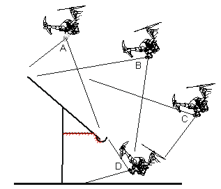 Figure 1: The visibility of the surface from different camera positions.
Figure 1 presents the visibility of surfaces when taking pictures of a typical building. It can generally be stated that taking photos from positions ’A’, ’B’ and ’C’ does not mean a problem. At the same time, however, it can be seen that from these positions the bottom of the eaves marked by a stripe can never be seen so a real surface of this area cannot be taken in 3D reconstruction. Camera position ’D’ is necessary to make pictures of the nonvisible parts. Unfortunately, in several cases this position is risky as the multirotor device carrying the camera stays very close to both the building and the ground. In the case of high buildings position ’D’ is relatively easy to carry out as the minimum height of the multirotor above the area is higher, too. If it is feasible that the flying device should not go lower than 1-2 metres, pictures from position ’D’ can also be taken. In the case of lower buildings taking pictures from position ’D’ is also feasible if the drone is taken by hand and setting its camera to a proper direction photos of the building can be taken.
In the case of buildings the lateral and, in many cases, upward camera position is of high importance. That is why the fixed-wing aircrafts are not suitable for this task. Multirotor devices are the most efficient camera carriers at the current level of technological development when surveying buildings. Although helicopter-like devices are able to perform a similar movement to that of multirotor devices but their mechanical design is much more complex. They are more prone to damage so their transportationis more complicated. The only disadvantage of multirotor devices is that they are unable to auto-rotate. It means when the power batteries are out these devices cannot fly. As flight is very close to buildings when surveying only the most developed multirotor devices with the safest features should be used. As a result of most recent developments the control panels of the 8-rotor-multicopters are able to stand in for an engine while properly controlling the other working ones. Using such instruments can significantly improve the safety of surveys. As the primary position data of multirotor flying objects are processed on the basis of on-board GPS good reception is essential. Unfortunately, it is the low flight and the covering of the building that can negatively influence GPS reception. Weak GPS data result in the multiposter’s apparent swift and imbalance, which has to be compensated by the operator. Although this position keeping flaw is not dangerous on its own, it can really be a cause for concern due to the proximity of the building or any other objects. During flights close to objects it is not practical to apply automated flight lines as its precision is not satisfactory. In many cases blocked live images of the camera must also be taken into consideration as higher buildings can shadow the frequency of the video signal carrier. For security reasons it is practical to plan flights during which the operator can see the multicopper. In practice, it means that the flying object must be accompanied round and round the object on the ground.
The automated point pair search in the pictures makes standard photo taking from all directions unnecessary. Attention must only be paid that every part of the given building should be recorded in as many pictures as possible so a lot of overlapping pictures should be taken.
Practical experience says that pictures of 3-4 m are necessary for good quality reconstruction by means of a 12 megapixel camera free from distortion.
Figure 2 illustrates the process of photographing a small chapel. The positions of making the single pictures can be seen above the building in the picture together with the optical axis of the camera at the moment of taking pictures. It can also be seen that in the survey the pictures that should have been taken upward next to the building from position ’D’ of Figure 1 are missing. Despite the missing photographs 3D reconstruction could be carried out although at some parts of the building it is of bad quality (Figure 3).
 Figure 2: The spatial position and orientation of pictures taken when surveying a chapel.
The order of making photos is not fixed, which means that pictures can be taken discretionary even randomly. The only criterion is that all parts of the object must be photographed and each part should appear in several pictures. In the case of a bigger building this requirement can be met if pictures are taken systematically such as taking pictures around the building (Figure 2). The practical implementation of going round the building can sometimes be defined by the nature of the building in many cases. The tower in Figure 4 is a narrow but high building. By choosing the more favourable and simpler way when photographing, pictures are taken ’up and down’ alongside the four sides. It is worth noting that while taking pictures of the tower (Figure 4) the photos taken from position ’A’ of Figure 1, i.e. above the top of the tower, are missing. However, 3D construction was successful as the pictures taken of the entire roof structure from positions ’B-C’ of Figure 1 have the necessary overlapping.
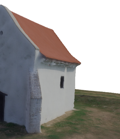 Figure 3: Part of the reconstructed chapel under the eaves full of serious flaws.
In an extreme case pictures randomly taken are also suitable for 3D reconstruction provided the meet the requirements outlined above. At the same time, in the case of random photographs part of an object may sometimes be missing or not apparent in several pictures so that is why systematic photography is recommended.
 Figure 4: The process of taking pictures of a high tower.
Figure 5 presents the 3D model of such a building where parts nonvisible from above are significantly represented. As a result of applying position ’D’ of Figure 1 the vaulted joist of the passage of the building is also visible (Figure 5 (a)). Of course, this part of photography calls for utmost care as flights should be carried out extremely low and close to the building. In cases if the suspension of the camera system of the robot aircraft makes it possible, pictures can be taken by the manually rotating the multicopter (as if it was a handicam). It is important that the pictures taken ’manually’ should be taken by a similar camera system and image fittings must be flawless.
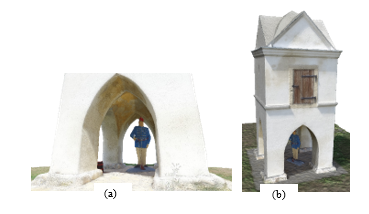 Figure 5: Display of parts of the historical tower non-visible from above.
The building to be photographed cannot always be freely accessible. If the walls of the building are at least laterally visible it is possible to make a correction of limitedly removing the trees or other covering object while processing.
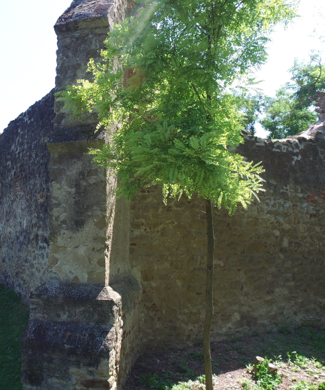 Figure 6: The tree next to the wall of the building impedes photography.
The tree on Figure 6 does not make it possible for the multicopper to make a picture of the wall of the building freely. At the same time, however, the tree doesn’t over the wall laterally so part of the wall covered from the front can be constructed from the necessary number of lateral photos. If no correction is made in processing, the 3D model will contain the tree and the wall, as well. By making use of the fact that the entire wall can be reconstructed the point cloud making up the tree can be removed during the 3D edition. It is important that such corrections be made on the point cloud serving as the basis of the model and not on the model ready. The 3D model of Figure 7 was made after the digital removal of the tree. The shadow of the tree is visible on the model but the tree itself no longer covers the building, so it is accessible.
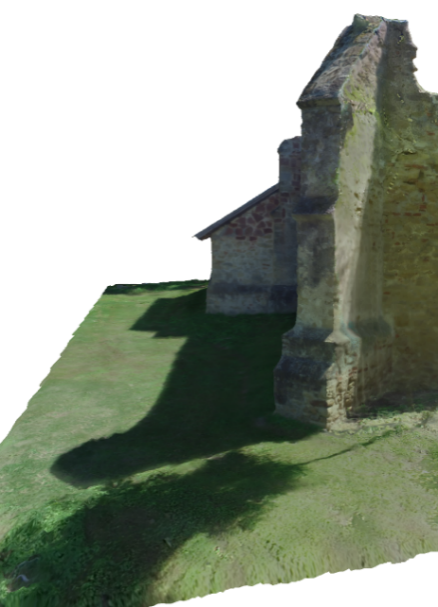 Figure 7: The result of digitally removing the tree in the 3D model.
The spatial point cloud generated while processing is connected with elementary triangles by the programmed. These triangles make up the surface, which is the 3D model of the area already surveyed. Of course, the number of polygons or any other means to detail the surface can be stated here. The ready-made 3D model can be displayed from a discretionary point. The model contains only surface, i.e. the polygons covering the surface have no thickness. In a further step of processing texture can be fitted on the 3D surface. The texture is made by the programmed by means of the photo analyzed in the previous steps. If we take the chance of correcting the 3D point cloud then the automated use of the pictures serving as the basis of the texture is practical to be manually modified. In this concrete case removing the tree itself is not enough. To have the proper texture the parts depicting the tree must be excluded from the photos of the given area. In this case the program prepares the texture of the part concerned based on the pictures of the wall if they exist.
 Figure 8: Ruins of a church from the Arpad era following retouching the neighboring trees.[1]
The 3D surface model (Figure 8) is created by exporting the ready-made 3D model and one or more image files containing the texture (it depends on the size and the details of the model itself). All these files are necessary to display the D objects presented. Display itself is possibly by using several programmed such as the freely accessible and downloadable MeshLab programmed.
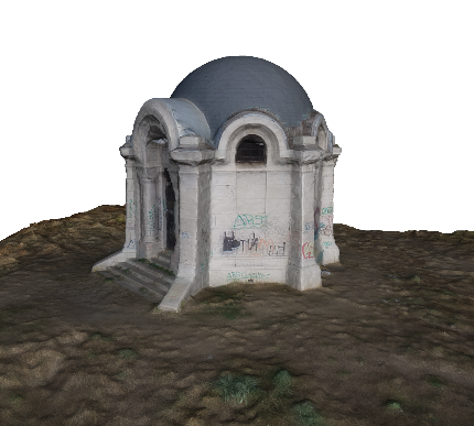 Figure 9: The mausoleum of the Lupe family in Pumas.[2]
5. Further3D models
Figure 9 presents the 3D reconstructed pjoto of the mausoleum of the Luppa family from Pomáz. The model of the mausoleum was made on the basis of 160 photos of 12 megapixels by using Agisoft Photscan software. The pictures were taken by a DJI Inspire 1 drone within one take-off of 15 minutes of flight. By walking round it in the virtual space the demolished state of the mausoleum is visible. From an aesthetic point of view several graffiti ruin the sight of the monument, which are also displayed on the reconstructed photo. It is interesting to note that the graffiti mentioned above are advantageous from the point of view of 3D reconstruction as it is easier to find contrasting point pairs when fitting the parts of the picture together than in the case of homogenous whitewashed walls.
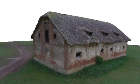 Figure 10: A deserted farmhouse near Nádudvar.[3]
Figure 10 presents the 3D reconstructed picure of a deserted farmhouse. The farmhouse is approximately 8,2 m high, 25,8 m long and 10,8 m width. The model of the house is based on 160 photos of 12 megapixels by using Agisoft Photscan software. The pictures were taken by a DJI Inspire 1 drone within one take-off of 15 minutes of flight. When these photos were made, it was gloomy so the contrast of the reconstructed picture is a bit beyond the ones made in sunny weather but it proved to be advantageous for reconstruction as there were no shadows and lighting proved to be constant when going round the entire building. The model reconstructed is detailed enough to reflect the state of the house. The mortar coming off and the bricks used for the walls staying bare are visible.
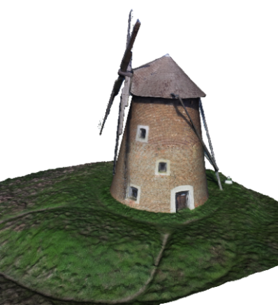 Figure 11: A renovated windmill in Kulcs.[4]
Figure 11 presents the 3D reconstructed photo of a renovated windmill. The model of the windmill is based on 160 photos of 12 megapixels by using Agisoft Photscan software. The pictures were taken by a DJI Inspire 1 drone within one take-off of 15 minutes of flight. hen taking pictures, utmost care must be paid to the thin wooden structure of the mill as reconstructing thin parts is usually difficult.
 Figure 12: Pad chapel.[5]
Figure 12 presents the 3D reconstructed picture of a dilapidated chapel. The chapel is approximately 15,7 m high, 13,3 m long and 7,3 m width. The model of the chapel is based on 285 photos of 12 megapixels by using Agisoft Photscan software. The pictures were taken by a DJI Inspire 1 drone within two take-offs of nearly 30 minutes of flight. When the pictures were taken it was typically sunny but the sun was shaded by clouds for a short time. Due to this fact, both sunny and cloudy pictures were taken of the building, which proved to be useful in 3D reconstruction. As a result, the ready-made model is contrastive but free from the distortions of heavy shadowing. Reconstructing the cross at the top of the church requires special care and reconstruction of proper quality needs up-close photos of the cross and a small part of the dome. To this end, pictures of the top of the tower were made while the multicopter went round the cross at a distance of 4 metres. Pictures were once taken from the bottom and from the top of the cross. Despite the up-close photos the manual filtering in the 3D point cloud was necessary during the reconstruction of the cross due to which the points created as faults by the programme were removed.
6. Results
Based on the experience of several experiments the requirements of successful 3D reconstruction can be outlined.
Regarding environmental conditions diffuse light is the best for reconstruction, which corresponds with slightly cloudy weather. Suitable pictures in direct sunlight can only be made if the object moderately reflects light of a non-homogenous, i.e. well-structured surface. The 3D reconstruction of the shadowy side of objects with homogenous white surface such as several churches and chapels could only be carried out in significantly weaker quality (roughness of surface) in direct sunlight.
Regarding the cameras applied the parameter of the objectives is of great significance in addition to high resolution (of at least 12 Megapixels). Most pictures were taken by an objective of 20 mm working distance of, 12.4 Megapixels with 6.17×4.55 mm CCD sensor. In many cases very proximate fights were necessary to provide enough details. It can be proved by practice that experiments yield better results with an objective of 34 m working distance of 16.0 Megapixels with 17.3×13.0 mm CCD sensor. In case of the latter one there is no need for dangerously approaching the object to have the necessary details.
Follow-up filtering proved to be necessary for several objects. In all cases filtering meant removing excess or disturbing points of the 3D point cloud. In some cases parts of the pictures deleted had to be removed, as well. However, it is important to note that the preliminary image improvement of the pictures used for the reconstruction significantly damaged the final result of the reconstruction. That is why exclusively unprocessed pictures could be used for processing.
The 3D models of the paper and further models of drone pictures are accessible at https://sketchfab.com/fuhur.
- J. Albertz, Albrecht Meydenbauer – Pioneer of Photogrammetric Documentation of the Cultural Heritage, Proceedings 18th International Symposium CIPA 2001, pp. 19-25, Potsdam (2001).
- M. Marghany, M. R. B. M. Tahar, M. Hashim, “3D stereo reconstruction using sum square of difference matching algorithm”, Scientific Research and Essays, Vol. 6(30), 6404-6423 (2011) [doi:10.5897/SRE11.1661].
- Ildiko Horvath, Anna Sudar, „Factors Contributing to the Enhanced Performance of the MaxWhere 3D VR Platform in the Distribution of Digital Information”, Acta Polytechnica Hungarica Vol. 15, No. 3, 2018 [doi: 10.12700/APH.15.3.2018.3.9].
- Borbála Berki, 2D Advertising in 3D Virtual Spaces”, Acta Polytechnica Hungarica Vol. 15, No. 3, 2018doi: 10.12700/APH.15.3.2018.3.10].
- Şasi, A , Yakar, M., “Photogrammetric Modelling of Hasbey Dar’ülhuffaz (Masjid) Using An Unmanned Aerial Vehicle”, International Journal of Engineering and Geosciences, 3 (1), 6-11 (2018) DOI: 10.26833/ijeg.328919
- Doğan, Y, Yakar, M., “Gis and Three-Dimensional Modeling for Cultural Heritages”. International Journal of Engineering and Geosciences, 3 (2), 50-55 (2018). DOI: 10.26833/ijeg.378257
- H. Gernsheim, “The 150th Anniversary of Photography,” in History of Photography, Vol. I, No. 1, (1977).
- A. Grimm, “Der Ursprung des Wortes Photogrammetrie”, in Internationales Archiv für Photogrammetrie, Ackermann, F. et al., Ed., Vol. XXIII, Teil B10, Komm. V, VI, VII Nachtrag, pp. 323-330, Hamburg (1980).
- N. A. Matthews, Aerial and Close-Range Photogrammetric Technology: Providing Resource Documentation, Interpretation, and Preservation. Technical Note 428. U.S. Department of the Interior, Bureau of Land Management, National Operations Center, 42 pp., Denver, Colorado (2008).
- C. Harris, M. Stephens, “A combined corner and edge detector”, in 4th Alvey Vision Conference, Proc. AVC88, 147-151 (1988) [doi:10.5244/C.2.23].
- A. Willis, Y. Sui, An Algebraic Model for fast Corner Detection, in 12th International Conference on Computer Vision, Proc. ICCV.2009, 2296-2302 (2009) [doi:10.1109/ICCV.2009.5459443].
- Ulvi, A , Toprak, A., “Investigation of Three-Dimensional Modelling Availability Taken Photograph of The Unmanned Aerial Vehicle; Sample Of Kanlidivane Church”, International Journal of Engineering and Geosciences, 1 (1), 1-7 (2016) DOI: 10.26833/ijeg.285216