Semi-Autonomous Robot Control System with an improved 3D Vision Scheme for Search and Rescue Missions. A joint research collaboration between South Africa and Argentina
 , Nicol Naidoo 2, Glen Bright 2, Maria Lorena Bergamini 1, Jose Zelasco 3, Francisco Ansaldo 3, Riaan Stopforth 2
Adv. Sci. Technol. Eng. Syst. J. 3(6), 347–357 (2018);
 DOI: 10.25046/aj030643
Rescue operations require technology to assist the rescue process. The robotic technology in these missions is becoming very important. The important aspects investigated in this study are the integration of a mechatronic system that will allow for a robotic platform with a vision system. The research collaboration between Argentina and South Africa is discussed, with the correlating research areas that each country investigated. The study permitted the development and advancement of a search and rescue system for different robots (wayfarer and drones) with different vision capabilities. A novel and innovative vision approach is presented.
1. Introduction
This paper is an extension of work originally presented in the 24th edition of the Mechatronics and Machine Vision in Practice (M2VIP) [1].
Search and rescue (SAR) is a general field referring to an emergency response to locate, give aid, medical care and to rescue people. Urban SAR (USAR) is considered a multiple-hazard discipline [2]. Urban environments are often more susceptible to human induced disasters: major industrial and/or transport accidents and/or fires, terrorism, wars, etc. or can have enormous effects in case of extreme natural phenomena like earthquakes, hurricanes, etc.
SAR operations in dangerous, disaster or catastrophe areas can be greatly improved with the assistance of tele-operated robots and/or semi-autonomous robots. Current implementations of mobile robots for SAR operations require human operators to control and guide the robot remotely. Even if human operation can be effective, operators may become stressed and tired rapidly [3]. In addition, current autonomous robots are incapable to work properly by moving in complex and unpredictable scenarios. This challenge could be addressed with a correct balance between the level of autonomy of the robot and the level of human control over the robot [4].
The first phase in a rescue mission is to identify the target area. The goal is to obtain a precise evaluation of the number and location of victims, detect dangerous situations for rescue personnel or survivors such as gas leaks, live wires, unsafe structures, etc. Semi-autonomous robots carrying correct sensors can obtain data from the field without risks of SAR personnel, and (if connected) can report on line important information. In the other hand, because time is critical during search and rescue operations in catastrophe areas, personnel do not have to waste time waiting for initialization and preparation for robots in the field. The robots must be deployed as soon as possible; if not, the acceptance of the technology by rescue personnel could prove difficult [3].
The mining activity in South Africa has a long list of victims of accidents. This is a case among others, where semi-autonomous mobile robots can access into unstable and toxic areas, in mine shafts, in order to identify dangerous areas, and to save accident victims and rescuers [3]. Argentina had also events in which the use of semi-autonomous robots could have been useful in SAR operations: terrorist attacks, mudslides, and the recent disappearance in the ocean of the military submarine ARA San Juan.
The development and deployment of technology associated with SAR robots will also have a direct benefit to people who live in poor neighbourhoods of South Africa, and Argentina, and in many other circumstances. Fires and mudslides can have a devastating effect in low cost housing developments and the SAR of victims can be improved with technologically advanced semi-autonomous SAR robots. In addition, SAR operations in other disaster cases like, floods [5], mudslides [6], earthquakes, avalanches, fallen buildings, nuclear fusions, explosions, terrorist attacks, forest and/or industrial fires, recovery and deactivation of bombs, etc. can be greatly enhanced with the aid of semi-autonomous robots [7].
SAR personnel use semi-autonomous robots to improve SAR operations. These robots help to recover wounded or trapped people in disaster areas that are dangerous or can pose a threat to human rescuers. SAR operations using semi-autonomous robots can be carried out faster without risk for the SAR personnel. An advantage of using semi-autonomous robots in SAR operations is that they are not susceptible to toxic agents as gases, radiation, acidic or alkaline spills, etc. where toxicity could be dispersed. So, they can access to areas where rescuers cannot reach, or they can do it by risking their lives. If an accident occurs during the operation, there is no injury or loss of human life.
The collapse of the buildings of the Twin Towers in New York (USA) [3], recent catastrophes such as the Fukushima nuclear disaster in 2011 or Nepal earthquake in 2015 showed that SAR or USAR robots can be used to efficiently support rescue teams in finding persons in danger or gathering information more effectively. In Fukushima emergency responders deployed a SAR robot, to check on conditions in the surroundings and allowed workers a safe distance from hazardous radiation [8].
It is proven that semi-autonomous robots are a very useful tool for SAR operations showing the need to investigate how to improve the capacity of SAR robots around the world.
The objective of the joint collaboration of scientific and technological research between South Africa and Argentina is to research, design, develop, assemble and test different systems to improve the functionality of semi-autonomous robots for SAR operations and to improve the quality of life of inhabitants by carrying out rescue enhanced SAR missions in South Africa and Argentina.
The main objective of this paper is to discuss and to analyze the design and development of a semi-autonomous robotic platform that can be implemented in SAR missions in order to improve the results of the operations, as part of the joint research collaboration between South Africa and Argentina. An underlying objective is to remark the importance of the need of research and development of semi-autonomous robotics in order to assist to SAR operations. As an interesting result, in this paper, a simple and promising approach to 3D vision is presented.
The structure of this paper is as follows: Section 2 discusses the methodology of the research collaboration between South Africa and Argentina; Section 3 identifies the basic components (building blocks) of navigation and local control in robots and discusses the need for a middle-ware service. Section 4 presents the different vision algorithms, techniques and hardware used: the vision system, called here: “The Vision-Ware”. Section 5 visualizes the design of a robot control architecture for SAR applications that will be integrated with the middle-ware. Section 6 discusses conclusions and future works.
2. Methodology
The methodology consists of research, design, simulation, development, assembly and testing of different subsystems for semi-autonomous mobile robots in SAR operations. The objective of the research collaboration is to research and develop innovative solutions related to vehicle chassis design, propulsion, navigation, guidance and orientation and 3D vision of the robot.
The methodology will allow the development of new technologies that can optimize the performance of robots in hostile environments so that vehicles can perform the necessary SAR operations reducing risks for human lives.
The research methodology will also focus on the study of new technologies that can be integrated on board of the semi-autonomous robot in order to deliver the necessary first aid equipment and to recover data from field. The methodology includes the development of simulations that will show the viability of subsystems developed and the performance of the robots in different tasks.
The University of KwaZulu-Natal has integrated a drone (Phantom 3) and a prototype platform (Segway RMP400) for vehicle design and propulsion technologies for semi-autonomous mobile robots. Further development and control of this system will be researched and investigated to allow semi-autonomous and autonomous control for SAR purposes.
Argentinean researchers will continue with the investigations carried out in mono and stereo vision, and the integration of cameras, which will help with the location of victims in a disaster environment and navigation and control of the semi-autonomous robotic platform.
3. Background
3.1. Brief and Trends of SAR Robotics
There is a vast literature related development of SAR Robots. Some papers that can show trends are mentioned bellow.
Actually, because of the most SAR robots are tele-operated, and autonomy robotics do not fit conditions for work and transit in complexity of SAR scenarios, a strong trend is the research and development of semi-autonomous robots, trying to obtain a good balance between the level of autonomy of the robot and human control over the robot [4].
Area mapping and localization for SAR missions research topic since many years, made good progress in terms of performance. A low bandwidth radar-based scanning-technology for mapping is presented in [9]. The radar technology is capable of showing a substantial mapping quality [8].
Swarm robotics consists of a large number of simple and tinny robots working together that perform tasks of greater complexity. It is strongly focused in coordination, cooperation and collaboration. In particular for swarm robotics applied to SAR operations, optimization algorithms for hazardous environments and laborious tasks were proposed and development [10].
In [11], a case study of IOT application for SAR operations based on cloud is presented. A large-scale deployment of IOT devices in catastrophe scenarios controlled by a cloud based application implementing a “Robot-as-a-Service” scheme (RaaS) giving to SAR operations the advantages of cloud schemes applied to the use of robotic resources: flexibility, cost-efficient, scalability, and virtualization, between others.
3.2. Local Navigation and Control
A very important goal of long term research is the development of a robust navigation area mapping system for mobile robots for unknown and changeable scenarios [12].
The following building blocks of navigation are identified [12, 13]:
- Perception: the robot must obtain field data (raw-data) from their sensors and interpret it and convert it into useful information. Low-level sensing processes extract basic features such as highness or line segments, while high level sensing processes use symbolic models or geometric templates to constrain the sensor interpretation.
- Localization: The robot must identify its position in the field. To achieve this, the robots must have a location support system such as a GPS. If it is not possible, they must recognize the environment in order to know their position on the map. Even more: in several disaster areas, scenarios can vary from saved information. Autonomous vehicles must rely on information obtained from sensor data. They have to be integrated into a unified and consistent mapping model. The positional drift of the sensors due to the robot motion has to be taken into account in the mapping and navigation procedures.
- Cognition: the robot has to decide how to achieve its objectives in the target zone by planning a convenient path (the shortest one in a specific sense).
- Motion Control: In order to move over a planned path, the robot must control and drive its engines connected to its traction system.
In addition to these building blocks, robots must avoid any obstacle, static or dynamic, that may be present on the way to the goal. And if this is not possible, they should be able to plan a new path on the fly. Figure 1 shows a diagram containing the necessary components for the design of semi-autonomous robot system. Regarding to remotely controlled mobile robots, tasks like location, sensing and perception and a part of the cognition module must be controlled locally, in a decentralized manner.
The heterogeneity of the members of a team of robots as well as the information that comes from their various sensors is an advantage that can be used in favor of the success of the mission. For example, in case of an earthquake, a quick picture from a drone can shows the general situation with the possible rescue targets. Then mobile robots like Segway-based ones, more robust and equipped, can be sent to the target area. Meanwhile, some vital elements can be delivered by drones. Or in a coal mine, a first line of robots can obtain images and gas information in order to be used by rescuers. Once the risky environmental information has been obtained, rescuers will be notified, so they can be prepared [14]. If it is safe for rescuers, they can go ahead and reach the robots and then, operate them continuing with the SAR mission.
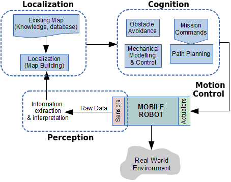 Figure 1. Control structure for autonomous mobile robots
For a collaborative success, the deployed network of robots must use a service software, known as the middle-ware layer.
3.3. Middle-Ware for SAR Robotics
The middle-ware can be seen as the glue that connect everything in the robotic network. It should be designed to allow easy integration of each robot into the network, especially considering that in semi-autonomous robotic implementations for SAR operations, the system configuration time is a critical factor. Another important point that can influence in the direction of the mission is the level of intelligence assigned to the robotic resources for the search process. The middle-ware should provide software interfaces that mask the heterogeneity between the different robots in order to promote cooperation among the robots. This approach allows a more efficient use of the technological resources in order to positively affect the duration of the mission. And considering that time is critical, this will also influence in the final result of the mission.
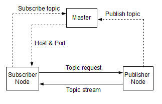 Figure 2. Communication in ROS
The ROS middle-ware consists of nodes, messages, topics and services, and the nodes communicate with each other in a peer-to-peer way (P2P) by publishing messages and subscribing to the messages posted [15]. An initial event called “naming service” is centralized and based on a master node, which is shown in Figure 2 [15].
A very common and difficult problem when installing a rescue robot in a catastrophe area is the maintenance of a permanent communication. It is expected that communications facilities have been destroyed or inoperative. Therefore, it should be assumed that local communication resources cannot be used, by limiting communications to the native of the system itself [16].
Below is the communication sequence between publisher node and subscriber node:
- Publisher registers a topic (e.g. a laser scan) to the master node informing the point of topic data.
- Subscriber requires the master on how to access to a particular topic.
- Master responds by sending the entry point data, host and part number.
- Subscriber communicates to publisher (host) via TCP or UDP connection requesting for topic data.
- Publisher responds by sending the topic data stream (e.g. laser scan data).
The ROS has been modularly designed. It is organized in packages containing nodes, configuration files, libraries, databases and third party software. So, this packages can be easily integrated into the ROS framework. Exist a wide range of ROS packages available for various robotic implementations such as sensor/actuator drivers, robot path planning and navigation, robot simulation, and others [17].
3.4. Robotic Vision
Computer Vision is a discipline whose main objective is the identification and recognition of objects within digital images, normally acquired by digital cameras. In many applications the identification of moving objects in video captures is required. In addition, in some applications this is required to be achieved in real time. The strategies used for the identification of objects in digital images are based on the analysis of the edges or the study of the whole image or a partial window where the object is probable to be in [18]. The strategies based on edge analysis use techniques to detect lines and edges such as thresholding [19, 20] or by the use of different filters [21] to then extract the characteristics of the shape using digital topology [22, 23] or by recognizing patterns obtained from the border. The strategies based on the analysis of the complete area of the image obtain characteristics of the object contained in the image through training and pattern recognition techniques using neural networks [24], genetic algorithms or using the wavelets transformation [25]. The discretization of the image data, the resolution of the camera, the lack or excess of brightness, the obfuscation, cause lost of clarity or noise in the image, which requires extra treatment [26-28] that in many cases avoid real time requirements.
The robotic vision requires converting the two-dimensional information of the scene obtained from images recorded by cameras into a three-dimensional model in order to recognize objects and places, in order to correctly execute the assigned tasks. Stereoscopy is a technique that imitating human vision, from two images of the same scene achieves a three-dimensional reconstruction [29]. The computation is achieved after the recognition of homologous points in both images. However, this task requires testing the matching of millions of pixels in millions of possible combinations [30] which compromises the requirements for recognition in real time.
The use of commercial 3D cameras for robotic vision can be expensive and heavy. In the other hand, proprietary technology limits several implementations. The aim of the 3D vision research is to develop a cheap, flexible and open solution with stereo cameras that can generate the 3D reconstruction using stereoscopy in different scenarios.
3.5. About the Research Collaboration between Argentina and South Africa
Within the framework of the Scientific-Technological Cooperation Program between the Ministry of Science, Technology and Productive Innovation of the Argentine Republic (initials in Spanish: MINCyT) and the Department of Science and Technology of the Republic of South Africa (DST), the project called “Semi-Autonomous robots for SAR operations” was selected by the Bilateral Commission MINCYT-DST to be executed in the 2014-2016 triennium under code SA / 13/13.
In charge of the South African part was Dr. Glen Bright of the Mechanics Department of the Kwazulu-Natal University, while in charge of the Argentina part was Dr. José Zelasco of the Mechanics Department of the Faculty of Engineering of the University of Buenos Aires.
Phd students Nicol Naidoo and Jorge Kamlofsky have made progress in their researches. Engineering students from both universities have participated in the developments and attended the presentations of the progress of the project.
Throughout the project various equipment was acquired such as: drones, Segways, cameras and others. Committees of both countries have made presentations about the progress of the project and joint publications were achieved [1, 41, 47, 48]
Although it was not possible to present a functional prototype of rescue robot, the development of a middle-ware to integrate several robotic platforms was made. Several stages of a three-dimensional vision system were developed that prove to be very efficient. Much of this is shown in this work.
Challenges of this experience were the technical developments, the interrelation between the researchers of both countries and the active participation of the students.
4. The Vision-Ware: 3D Vision Algorithms and Hardware Integration
Artificial vision technology is based on a resemblance to human natural vision. Following the analogy with human vision, each eye receives a different luminous stimulus, the distance that separates them produces a parallax angle in the observed object. The image obtained in each retina is integrated and reconstructed in the brain that finally generates the perception of the relief. In order to imitate this reconstruction process, given a pair of images (obtained by cameras) called stereoscopic image, it is necessary to solve the following three stages: Calibration, pairing or put in correspondence of homologous points, and 3D reconstruction.
To obtain the three-dimensional reconstruction of an object present in two images, first, it is necessary to find it in both images. It continues with the pairing or finding of homologous points. This is: to find the location of the points of the object in the first image that correspond to the points of the same object found in the second image. Finally, by means of stereoscopy, the 3D coordinates of those points of the object can be calculated.
In this section, a model that for shape recognition uses just a few points of each object is presented. Therefore, it is attractive to use in real time robotic vision. Experimental data is presented.
4.1. Preparing 3D Models: Digital Camera Calibration
To perform the 3D reconstruction of a scene from multiple images by stereoscopy, these must be calibrated. At this point, the Fundamental matrix is a key concept since with the geometric information available, it allows to obtain the epipolar geometry of the scene from uncalibrated images [49].
If a point P of a three-dimensional referential system is projected on the left image as PL and on the right one as PR, (as shown in Figure 3) then the image point direction vectors in the same referential system satisfy the equation , where b is the displacement vector between the cameras: b = (Xc , Yc , Zc)T, or the coordinates of right camera in the 3D referential system, if the referential system is posed in the left camera. Since the three vectors are coplanar (epipolar geometry), the mixed product gives zero. By the use of the anti-symmetric matrix B:
The mixed product can be expressed as: PL . B . PR = 0. WL and WR are the coordinates expressed in pixels in the digital images of the points PL and PR expressed in length units related by the calibration matrix C as follows:
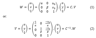 where W = (u , v)T coordinates of the point in images, (u0 , v0)T the principal point of the image, a and b focal distances, V = (x , y)T coordinates of the point in length units.
Because the reference is posed on the left camera, also a rotation of the right camera is considered. Matrix R represents the right camera orientation. Thus:
with:
F is the Fundamental matrix [24, 25, 31] with 9 parameters involved: 4 parameters for the camera calibration, 2 for the rotation and 3 for the base . It is a square matrix of order 3 and rank 2.
When the calibration is known, only the parameters of B and R are unknown. In this case, it is easy to obtain the essential matrix E = B . R [32] from the Fundamental matrix, since There are several approaches to obtain the 5 involved parameters [33 – 37]. The usual method involves the singular value decomposition of the Essential matrix [38].
Many methods have been proposed in order to calibrate the camera. In [47] is proposed a very simple calibration scheme, which is easy to implement. An assumption made is that it is quite easy to measure the X and Y coordinates of the camera point of view in relation to a 3D referential system when the camera optical axis has a small rotation angle with the Z axis. It is accepted that the error in the Z coordinate of the point of view is less than +/- 1cm. The error in the calibration parameters were obtained and evaluated in [47]. In a later step, assuming that two cameras have a small angle in relation to the Z axis, the calibration parameters error were evaluated and corrected, knowing the distance between two benchmarks in relation to the one calculated by stereoscopy. Regarding the Essential matrix [39], a method for getting the base B and the rotation R, with the solution of linear systems was used [47].
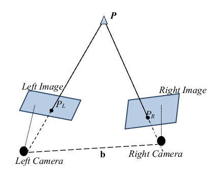 Figure. 3. Epipolar geometry
Calibration parameters are necessary to obtain more precise 3D coordinates of the scene points obtained by stereoscopy.
4.2. Computer Vision (2D): Finding Objects in Images
The interest in recognizing objects within digital images has two main areas of application: obtaining information from images for subsequent human interpretation and processing scenes for autonomous robotic vision [21]. In this last area, for the quick movement and efficient realization of the tasks for which the robot was built, it is especially critical that the processing of the images acquired by the robot, must be done in real time.
The following tasks (detailed below) are necessary to find objects within the images: Image Acquisition, image binarization: separation of objects of interest from the bottom (the complement of objects set), border acquisition: the boundary between objects set and bottom, border simplification: polygonalization, obtaining the curves descriptor pattern, patterns matching. All these tasks have been developed with the premise of realizing as soon as possible, approaching so, to the real time requirements.
Image Acquisition: A Digital Image is a two-dimensional luminous intensity function f (x , y), where x and y denote the spatial coordinates in the image and the value of f at the point (x , y) is proportional to the brightness or gray scale of the image at that point.
To acquire a digital image, an image sensor and the capability to digitize the signal from sensor is required. A sensor could be a monochrome or a color camera [21]. The gray scale of images vary depending the image type. RGB mode is commonly used in programming. In the RGB color images each pixel has three components: Red, Green and Blue, where each component represents the amount of each color in values between 0 and 255 (or one byte) where 0 indicates absence of color and 255 means full color. Thus colors can be represented with 3 bytes or 24 bits. Each point of the digital image is called a pixel. A simple color RGB image has millions of pixels. And each pixel can present color values between 0 and 24 bits.
Image Binarization: In Computer Vision it is convenient to work with binarized images. This is achieved by changing the value of the gray scale by a 1 or a 0. The objective is to separate objects of interest from the background of the image by a process known as “segmentation by thresholding”. The simplest way to do this consists of traversing each pixels of the image and assigning a in the gray scale “1” if gray scale conditions are higher than a defined threshold value and “0” otherwise. In this way, a “binarization of the image” is achieved [21]: grouping pixels of objects of interest with one value and pixels of the bottom with the other one.
In other cases, thresholds have to limit color ranges. Thus, multiple thresholds have to be defined: maximum and minimum threshold in each channel: red, green and blue.
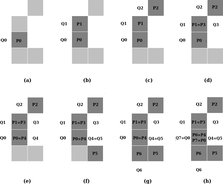 Figure 4. BF8 Algorithm example: (a) Starts in (Q0 , P0). (b) First pair obtained looking 8-neighborhood of P0, going clockwise: (Q1 , P1). Next iterative part illustrated from (c) to (g). Algorithm stops in (h).
The Borders: The objects obtained by binarization of the image are delimited by their borders. A simple algorithm for drawing edges was presented in [22]: BF4 or BF8 depending on whether 4-neighborhoods or 8-neighborhoods are used.
BF8 algorithm is sketched as follow: Given an initial pair of points (P0 , Q0) obtained by traversing the image, where P0 is part of the object (P0 = 1) and Q0 is the previous point that is part of the bottom (Q0 = 0). It gets iteratively pairs of points (Pi , Qi) looking the 8-neighborhood from Pi-1 going clockwise (or anti-clockwise) where Pi is the next 8-neighbor of Pi-1 that is a part of the object and Qi the previous point of Pi that is part of the bottom. BF8 stops when Pi = P0 and Qi = Q0. The set points of the edge is: {P0, P1, … , Pi-1}.. Figure 4 illustrates algorithm BF8.
BF4 is similar than BF8 but using 4-neighborhoods. With BF4 a thicker edge is obtained, with more points, while with BF8, the edge is thinner, with fewer points. Because of this, the second case is faster.
The edges allow to separate the objects from the background and thus be able to be treated as open sets of the Digital Topology [23]. The shapes of the objects can be characterized from the analysis of their edges.
Border Simplification: By polygonalizing the edges a simplified approximation of the edge curves can be achieved, and thus, an approximate representation of the object hundreds or thousands of times more reduced.
The polygonalization is done iteratively using the convex hull concept [45]: given a set of edge points, those that are inside a convex hull of width e will be eliminated. In this way, the sets of points that are approximately aligned, will be represented by the first and the last which will form two vertexes of a polygon. It will continue with next group of points and then, a new vertex of the polygon is determined till end point is the first point of the process. Figure 5 shows a diagram describing its operation. More details about this process can be found in [46].
The parameter e allows to regulate the compromise relationship between quality and performance: a larger e decreases the quality of the border simplification with greater speed. A small e ensures resolution in the approach. With a larger e, an approximation will be obtained more quickly. It is then left to the user to assume the compromise between resolution and performance through this parameter.
Obtaining of the curves descriptor pattern: From the polygonal curve, a descriptor pattern can be obtained based on the discrete evolution of the curvature parameterized by arc length [42]. It consists of a discrete function k(l) where k is the curvature (the interior angle) that corresponds to the evolution of the perimeter of the polygon parameterized by the arc length l. While the evolution of the perimeter l varies between [0, 1] because it is parameterized by arc length, the curvature accumulates a final value of 2p because it is a simple curve. It is clear that in the points of the polygon that are not vertexes, the curvature is zero. Therefore, only is interesting its analysis in the vertexes. However, from each vertex of each polygon a descriptor pattern can be initiated that will vary by shifting. After determining the orientation of each object [46], a point is defined from where to start each pattern. Thus, each object will be characterized by exactly one pattern.
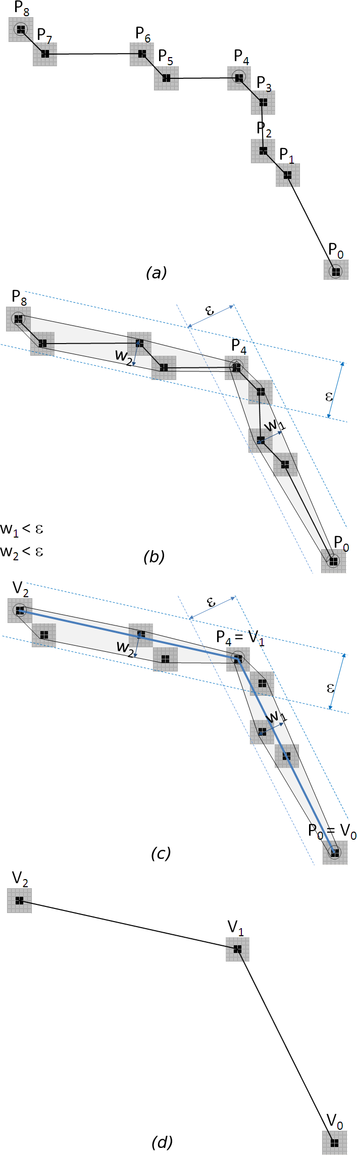 Figure 5: Simplification of curves using the wide convex hull e. (a) A portion of a digital curve composed of 9 points. (b) The convex hulls of width e are established. (c) The vertexes of the approximating polygonal are defined. (d) Interior points are eliminated and approximation established.
This pattern is invariant to rotations, translations and scaling, that is convenient when it is necessary to find similar objects instead of exactly equal object.
Patterns matching: Finding an object within an image consists of locating a descriptor similar to that of the pattern. To do this, the distance between both descriptor functions must be less than a threshold distance:
![]() Figure 6 shows a set of patterns corresponding to different objects. In black is shown similar patterns of similar objects.
Figure 6 shows a set of patterns corresponding to different objects. In black is shown similar patterns of similar objects.
Because in images normally objects could be in any orientation, these may be subject to transformations (explained in detail in [43]). Since objects are treated as polygons with reduced number of vertexes, and polygons can be represented just with its vertexes [46], the transformations to all the objects can be performed by a product between the transformation matrix and the matrix formed by the ordered points of the vertexes of this polygon.
4.3. Fast Finding of Homologous Points: Preparing 3D models in Real Time
From the recognition of homologous points in both images (called also: “pairing points in images”), the position in the three-dimensional space can be calculated. However, this task requires the pairing of many points, which compromises performance requirements. A model to finding out homologous points was presented in [40] and mentioned in [1]. In this paper, performance improvements is presented. Experimental data is included.
Description of the Process: When an object is found in both images with the method described above, one homologous point is automatically defined (in both curves): the starting point of both patterns.
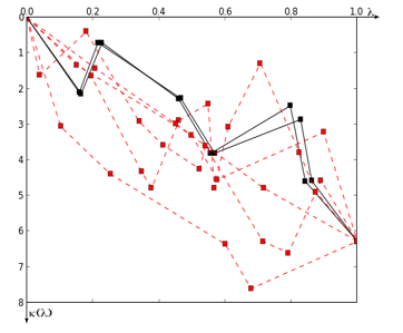 Figure 6: The Curvature Evolution Pattern of various objects.
Thanks to the fact that the curves are parameterized by arc length, and taking into account that the objects are similar, more homologous points can be obtained: this is achieved by traversing the vertexes of one of the curves, its counterpart is sought in the evolution of the normalized perimeter in the second curve, within a tolerance interval. For example, if a tolerance of 5% is performed and for a vertex i of the pattern of the first object with coordinates (l1i, k1i) = (0.200, 1.000), a vertex j in the pattern of the second object is wanted: (l2i, k2i) / 0.250 > l2j > 0.150 and 1.050 > k2j > 0.950. In case of a correspondence, the pair of vertexes (i , j) is added to the set of homologous points.
Performance Improvements: In [1] and in [40] it was shown that for the finding of the homologous points of an object in two images, it took 4.9 seconds. However, contemplating certain restrictions, the same finding could be achieved in times less than 1 second, for the same images.
In the process of objects recognition within digital images, it is intended to improve the performance in the reading of the images (mostly binarized or filtered) that the process provides as parameters.
This operation can be done faster without losing important details under the following assumptions:
- No objects of interest less than 10px wide.
- In a binarized image (black and white), the R, G and B components of the pixel are similar: 0 or 1.
- During the tracking of a moving object, the acceleration and velocity of movement of the object are known.
With these assumptions:
- The horizontal direction of reading of the image is done in discrete 10px jumps instead of being traversed pixel by pixel. If a value of interest is found in one of these jumps, 10 positions are retracted, and the current position is returned by consulting the values of the involved pixels one at a time and extending to the next 10 positions. If this operation was performed in the previous jump, the survey of the previous 10 positions is not carried out.
- If the image is binarized, the R, G and B components of any pixel are similar. Then, instead of requesting the R, G and B components, only one of them is consulted.
- If the speed and acceleration of the object is known, its location can be estimated, so that its search can be done within a reduced window, and not in the whole image.
As a consequence of the above, a great reduction in the time of the reading process of the images is obtained.
4.4. Stereoscopy: Building the 3D Model
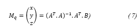
Starting with two images, knowing homologous points in both images, by the use of stereoscopy it is possible to perform a 3D re-composition of a scene based on these points. The more homologous points are known, the better the reconstruction will be. Thus, calculation of the 3D coordinates of each of these point (generically named here as Mq) is easily obtained by contributions of information from both images [30]. The spatial coordinates of the generic point Mq = (x , y , z)T are obtained by using the scene reconstruction equation (Equation 4) applied to each image: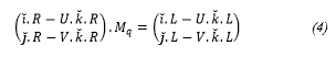
Where R is the rotation matrix of the camera, L = R . S with S the position of the camera in the general referential system, and U and V are x and y coordinates in length units of the projection of point Mq in each image. It is important to note that in this equations some parameters calculated in the Calibration step are used. Since Mq is unknown then Mq can be called as X, and (4) can be stated briefly as: A . X = B where A is a 2 x 3 matrix, and B is a 2 x 1 matrix. Then, contribution of the left image is: AL . X = BL and the contribution of the right image is: AR . X = BR.
Joining contributions of both images:
![]() Naming A = (AL , AR)T and B = (BL , BR)T, (5) can be presented as:
Naming A = (AL , AR)T and B = (BL , BR)T, (5) can be presented as:
![]() Where A is a 4 x 3 matrix, and B is a 4 x 1 matrix. Pre-multiplying by AT in both members of (6), and then by (AT . A)-1, 3D coordinates of the re-construction can be calculated as stated in (7):
Where A is a 4 x 3 matrix, and B is a 4 x 1 matrix. Pre-multiplying by AT in both members of (6), and then by (AT . A)-1, 3D coordinates of the re-construction can be calculated as stated in (7):
 The system is not canonical, that is, the independent term B does not correspond exclusively to the values measured in the images, therefore, even if the error of those measurements was known, the equations could not be weighted and the variance of the elements of the unknown vector could not be calculated.
Once points in spatial coordinates are obtained, the three-dimensional model of the scene can be achieved.
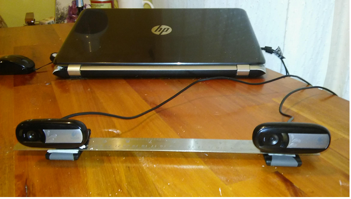 Figure 7: A notebook connected to two regular cameras mounted in a platform with known distance and orientation.
4.5. Hardware Integration
The three dimensional vision system is constructed using two regular cameras. One camera is placed in the origin of the referential system. The other one is located on the x axis, and thus, the referential system is fixed. The distance between both cameras is known, as well as the orientation angles. The greater the distance, the more accurate are the obtained spatial coordinates by stereoscopy. Current cameras can be connected directly to USB ports. And more than one camera can be connected to regular computers, as shown in Figure 7. Cameras are controlled by the vision software. Normally, drivers of regular cameras exist in most operative system; if not, drivers have to be installed from manufacturer’s site.
The Segway based robot is built to work in harmful environment. Thus, it is recommended to install an industrial computer, which is designed to work under more difficult conditions than regular computers.
Also with small size computers like Raspberry Pi-3 Model-B, 3D vision systems can be built. It is a good option in cases when weight and size availability is limited. In these boards with less than 50 grams and 50cm2, 64-bit processor, wireless connectivity and 4 usb ports are included. The base operative system is Raspbian: a specific Linux distribution. If it is not enough, other Linux distributions or Windows 10 for IOT could be installed. These boards can be used in a drone based robot. A different robotic vision system can be constructed with just one camera: images are taken after moving a known distance. The greater the distance between each image, the more accurate are the obtained 3D coordinates. Therefore, precision of 3D re-construction can be controlled by varying the distance between photos, with the height known. Figure 8 shows a Phantom 3 drone with an HD camera.
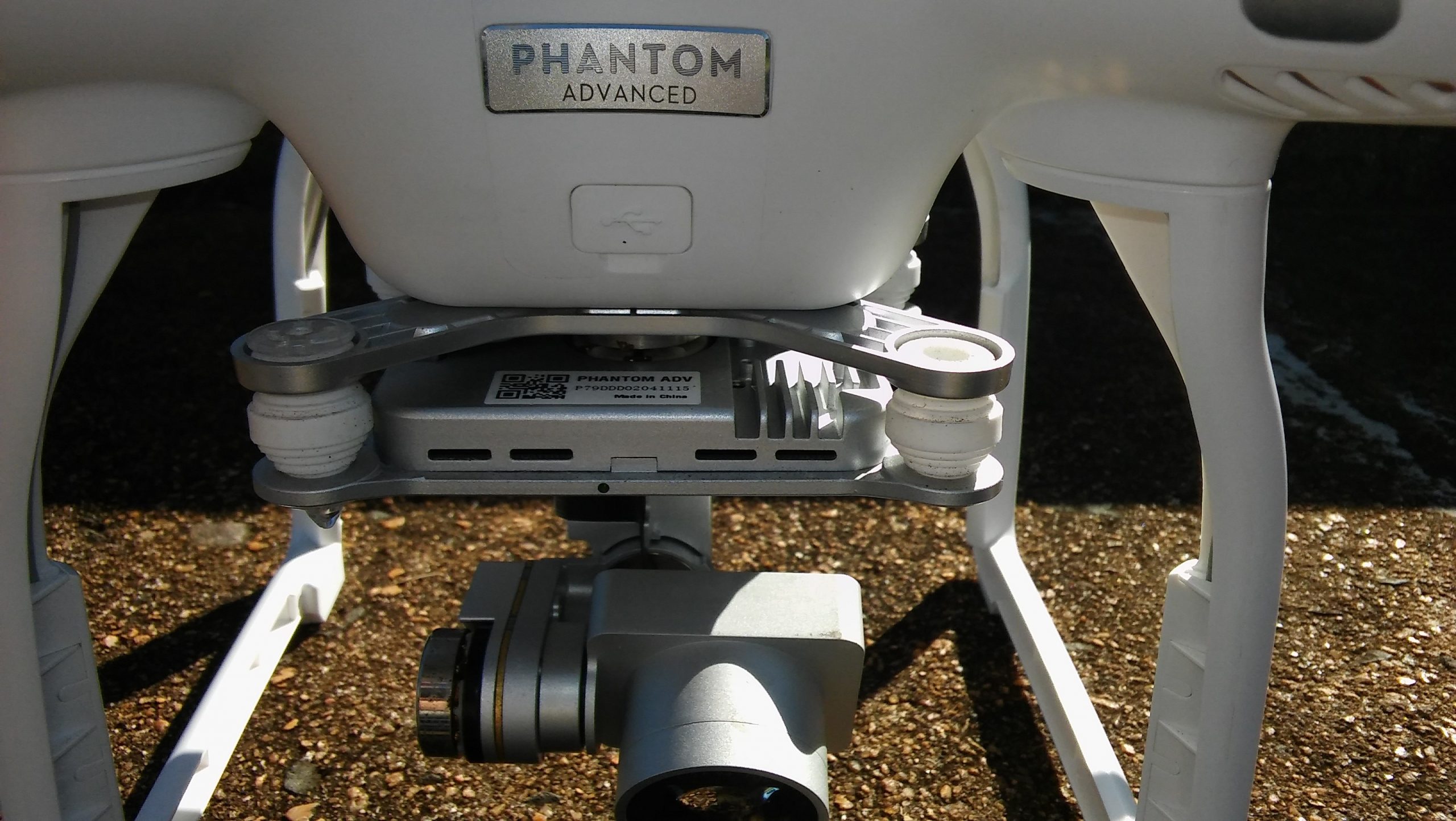 Figure 8: Phantom 3 drone camera with a stabilization mechanism.
In this project is tested the use of regular, IR and thermal cameras.
4.6. The Experiment
Brief Description: The experiment consists of obtaining the homologous points of an object present in two images, and measuring of CPU time consumed in each part of the process repeatedly.
Equipment Used and Settings: For the acquisition of images, two Logitech cameras C170 230mm distant were used. Being conventional cameras, the segmentation is achieved by placing objects on a white background. The algorithm was programmed in Python 2.7. The computer used is an HP Pavillion notebook with AMD A10 processor with 12Mb of Ram and 4 cores. The operating system used is Kali Linux: a Linux distribution based on a Debian kernel. Each image acquired has 640 x 480 pixels.
Values used: The width of convex hulls was e = 4. Tolerance in finding homologous point was 5%.
Results Obtained: The set S of homologous points obtained is:
S = {[(390 , 242) , (187 , 191)] , [(417 , 248) , (212 , 198)] , [(458 , 272) , (243 , 216)] , [(514 , 273) , (310 , 213)] , [(511 , 354), (307, 295)] , [(440 , 347) , (233 , 292)] , [(436 , 333) , (225 , 277)], [(351 , 329) , (146 , 281)] , [(274 , 294) , (73 , 256)] , [(250 , 265), (46 , 221)] , [(253 , 257) , (49 , 215)] , [(292 , 274) , (94 , 230)], [(341 , 277) , (140 , 227)] , [(388 , 244) , (181 , 196)]}
Between brackets the homologous points are presented. The first pair corresponds to the first image, while the second pair has its homologous in the second image. Points are expressed in pixels.
In Table, repeated measurements of CPU time consumed in each part of the process, is shown.
From the data showed in Table the average of the time of the process is 0,9199 seconds (less than 1 second). Figure 9 shows images used for the experiment with the homologous points.
Table 1: CPU times (in seconds) of pairing points in images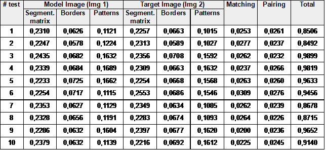
5. Control Architecture Design
Previously, the relationship between the level of autonomy and remotely assisted control in semi-autonomous robots for SAR tasks was discussed, and this is presented in this section. A hybrid control architecture is defined: an internal control block for automatic tasks, and a remotely assisted management and control scheme.
The robots have an internal control block that allow efficient time running of automatic tasks as: sensing, moving, obstacle avoidance, local path planning, etc. The robotic system have also a higher level of control called the “Navigation Control Center” (NCC) as shown in Figure 10. The objective of the NCC is to record and update the mapping models with the data acquired from the field and to assign a coverage area to robots and them to determine its navigation algorithm.
The control panel is the part of the NCC (not shown in the NCC block in Figure 10) where robots can be controlled remotely. The operators can request for information or tasks interacting through the graphical user interface (GUI) of the control panel, that will be developed in order to facilitate remote operation. A request made in the NCC is a high level task meanwhile in the local control block of the robot, it is transformed into a specific sequence of tasks just programmed. NCC and local control blocks are connected by a radio link.
The robots of the network will be powered by the ROS middle-ware. It consists of a master – subscriber/publisher nodes as explained in Section III and shown in Figure 2. ROS consist of the following software modules:
- Perception: ROS software drivers consist of packages of software that connect physical sensors with the operative system. Normally drivers are installed in the ROS in its last version. But in some specific cases drivers have to be installed. Depending of the kind of robot, different sensors will be mounted. While in a basic drone just one camera is carried, in the mobile robot based on a Segway platform a plenty of sensors could be installed: cameras, microphones, temperature, humidity, radiation, gas, etc.
- Localization: It is the module of software that calculates the position of the robot in the field, and dynamically builds the maps of newest areas or updates maps of known areas. The new information is shared with the NCC to optimize SAR process.
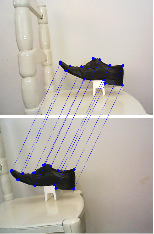 Figure 9: Homologous points of an object in two images.
- Cognition: This module has three important functionalities. The first one is the motors control module: provides electrical control of the motors that make physical actions of the robot such as to catch an object or to move from one site to another. The second functionality is obstacle avoidance: considers safety measures to prevent harm to persons, damages to the environment and to the robot itself. The last one is the local path planning: the objective is to make a surveillance in an area searching for humans that may require help or needs being rescue.
- 3D vision algorithm: this involves the processing of data from images acquired by the stereo cameras. By the 3D vision algorithm, data (images) are transformed into a higher level of information like an obstacle to be avoided or a possible alive person. This information must be shared with the NCC (so rescue personnel can be sent).
- Encode data: This module aims to collect, encode and send map data and data related to possible human recognition to NCC. Data compression and extraction is implemented in this module to improve performance of communications on sites where the existing communication resources could be very poor.
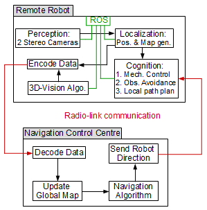 Figure 10. Robot communication and control architecture
A design factor that is a non-trivial problem is the possibility of radio-connectivity problems due to lost of signal strengths caused by interferences of the structures and constructions or because the geography of the site. To solve it can involve an in-depth research analysis, as discussed in [44].
6. Conclusions
In this paper, the need and convenience of the development for its later use in SAR missions of various semi-autonomous robots was introduced and presented.
Collaboration for research between Argentina and South Africa was established, which allowed researchers to make contributions for the design, development, simulations and testing of semi-autonomous robots based on different physical platforms: Segway and drone-based. A hybrid control architecture was presented between the remote robots and the control and navigation center. Interesting improvements in the 3D vision algorithms were presented, which seem to be promising since they would contribute to achieve three-dimensional modeling in real time.
Research results achieved during the binational project related to developments, knowledge exchange and active participation of students from both countries were presented.
Acknowledgement
The research presented in this paper is part of a joint collaboration between the University of KwaZulu-Natal, in South Africa, and the University of Buenos Aires, in Argentina. The authors wish to thank their respective governments for funding this research and for making the collaboration possible.
- N. Naidoo, G. Bright, R. Stopforth, J. Zelasco, F. Ansaldo, M. Bergamini, and J. Kamlofsky, “Semi-autonomous robot control system and with 3D vision scheme for search and rescue missions: A joint research collaboration between South Africa and Argentina.” In Mechatronics and Machine Vision in Practice (M2VIP), 24th International Conference on (pp. 1-6). IEEE, 2017.
- G. De Cubber et al., “Search and rescue robots developed by the European Icarus project, 7th Int.” In Workshop on Robotics for Risky Environments. 2013.
- Greer D., P. McKerrow, and J. Abrantes, “Robots in Urban Search and Rescue Operations”, © ARAA, In 2002 Australasian Conference on Robotics and Automation, 2002.
- B. Doroodgar et al., “The search for survivors: Cooperative human-robot interaction in search and rescue environments using semi-autonomous robots.” In Robotics and Automation (ICRA), 2010 IEEE International Conference on. IEEE, 2010.
- J. Casper and R. Murphy, “Human-Robot Interaction during the Robot-Assisted Urban Search and Rescue Response at the World Trade Center”, IEEE Transactions on Systems, Man and Cybernetics, Part B, Vol. 33, No. 3, 2003.
- R. Murphy and S. Stover, “Rescue Robots for Mudslides: A descriptive study of the 2005 La Conchita Mudslide Response”, International Journal of Field Robotics, Wiley, 2008.
- K. Kleiner, “Better robots could help save disaster victims”, 2006.
- S. Brenner, S. Gelfert and H. Rust. “New Approach in 3D Mapping and Localization for Search and Rescue Missions.” CERC2017: 105-111, 2017.
- P. Fritsche. and B. Wagner, “Scanning Techniques with Low Bandwidth Radar for Robotic Mapping and Localization,” in Informatics in Control, Automation and Robotics (INCINCO 2015). IEEE: 321-335, 2015.
- A. Kumar et al., “Search and rescue operations using robotic darwinian particle swarm optimization.” In Advances in Computing, Communications and Informatics (ICACCI), 2017 International Conference on. IEEE, 2017.
- C. Mouradian, S. Yangui, and R. Glitho. “Robots as-a-service in cloud computing: search and rescue in large-scale disasters case study.” In 15th IEEE Annual Consumer Communications & Networking Conference (CCNC). IEEE, 2018.
- A. Elfes, “Using occupancy grids for mobile robot perception and navigation.” Computer 6: 46-57, 1989.
- R. Siegwart and I. Nourbakhsh, “Introduction to Autonomous Mobile Robots”, MIT Press, Cambridge, Massachusetts, 2004.
- J. Zhao et al. “A search-and-rescue robot system for remotely sensing the underground coal mine environment.” Sensors 17.10, 2017.
- N. Naidoo, G. Bright, and R. Stopforth, “A Cooperative Mobile Robot Network in ROS for Advanced Manufacturing Environments”, in Proceedings of the International Conference on Competitive Manufacturing (COMA’16), 2015.
- S. Shin et al. “Communication system of a segmented rescue robot utilizing socket programming and ROS.” Ubiquitous Robots and Ambient Intelligence (URAI), In 14th International Conference on. IEEE, 2017.
- List of ROS packages for Indigo, http://www.ros.org/browse/list.php, last accessed 18 July 2017.
- D. Zhang, G. Lu, “Review of shape representation and description techniques”. Patt. Recogn., 37 (1),1-19, 2004.
- L. Davis, “A survey of edge detection techniques.”Computer graphics and image processing 4.3: 248-270, 1975.
- A. Rosenfeld and A. Kak. “Digital picture processing”. Vol. 1. Elsevier, 2014.
- R. Gonzalez, R. Woods. “Digital image processing.”Addison-Wesley Publishing Company, 1993.
- A. Rozenfeld, “Digital Topology”, The American Mathematical Monthly, 86(8) pp. 621-630, 1979.
- U. Eckhardt and L. Latecki. Digital topology. Inst. für Angewandte Mathematik, 1994.
- H. Rowley, S. Baluja and T. Kanade. “Neural network-based face detection.”IEEE Transactions on pattern analysis and machine intelligence 20.1: 23-38, 1998.
- A. Fernandez Sarría, “Estudio de técnicas basadas en la transformada Wavelet y optimización de sus parámetros para la clasificación por texturas de imágenes digitales”. Diss. Universitat Politècnica de València, 2007.
- J. Weaver, et al. “Filtering noise from images with wavelet transforms.”Magnetic Resonance in Medicine 21.2: 288-295, 1991.
- L. Rudin, S. Osher, and E. Fatemi. “Nonlinear total variation based noise removal algorithms.”Physica D: Nonlinear Phenomena 60.1: 259-268, 1992.
- T. Nguyen, I. Debled-Rennesson. “Curvature Estimation in Noisy Curves.” In: W. Kropatsch, M. Kampel, A. Hanbury (eds.) Computer Analysis of Images and Patterns, LNCS, vol. 4673, pp 474-481, Springer, Heidelberg, 2007.
- H. Moravec. “Robot spatial perceptionby stereoscopic vision and 3d evidence grids.”Perception, 1996.
- J. Zelasco et al. “Computer vision in AUVs: automatic roto-rectification of stereo images.”OCEANS 2000 MTS/IEEE Conference and Exhibition. Vol. 3. IEEE, 2000.
- Q. Luong and O. Faugeras, ”Determining the Fundamental matrix with planes:Instability and new algorithms”, Proc. Conf. on Computer Vision and Pattern Recognition, pp 489-494, 1993.
- Q. Luong and O. Faugeras,”Self-Calibration of a moving camera from Point correspondences and fundamental matrices”, International Journal of Computer Vision,22 (3), pp 261–289, 1997.
- H. Longuet-Higgins, “A Computer Algorithm for Reconstructing a Scene from Two Projections”, Nature, 293 (10), pp 133-135, 1981.
- J. Heikkila, “Geometric camera calibration using circular control points”, IEEE Transactions on Pattern Analysis and Machine Intelligence22(10), pp. 1066-1077, 2000.
- Z. Zhang. “A flexible new technique for camera calibration”,IEEE Transactions on Pattern Analysis and Machine Intelligence22(11), pp. 1330-1334, 2000.
- Z. Zhang,“Camera calibration with one-dimensional objects”IEEE Transactions on Pattern Analysis and Machine Intelligence26(7), pp. 892-899, 2004.
- H. Stewénius, C. Engels and D. Nister, “Recent Developments on Direct Relative Orientation”, ISPRS Journal of Photogrammetry and Remote Sensing 60, pp 284-294, 2006.
- R. Hartley and A. Zisserman, “Multiple View Geometry in Computer Vision”, Cambridge University Press, 2003.
- M. Kalantary and F. Jung, ”Estimation Automatique de l’Orientation Relative en Imagerie Terrestre.”, XYZ-AFT, 114, pp 27-31, 2008.
- J. Kamlofsky and M. Bergamini, “Rápida Obtención de Puntos Homólogos para Vision 3D”. In VI Congreso de Matemática Aplicada, Computacional e Industrial (VI MACI 2017) , 2017.
- M. Bergamini, F. Ansaldo, G. Bright, and J. Zelasco. “Fundamental Matrix: Digital Camera calibration and Essential Matrix parameters”. In International Journal of Signal Processing: 120-126, 1 (2016).
- T. Kanade and O. Masatoshi. “A stereo matching algorithm with an adaptive window: Theory and experiment.”IEEE transactions on pattern analysis and machine intelligence 16.9: 920-932, 1994.
- E. Lengyel. “Matemáticas para Videojuegos en 3D”. Second Edition, Cengage Learning, 2011.
- S. Chouhan, D. Pandey and Y. Chul Ho, “CINeMA: Cooperative Intelligent Network Management Architecture for Multi-Robot Rescue System in Disaster Areas”, in Proceedings of the International Conference on Electrical, Electronics, Computer Science, and Mathematics Physical Education and Management: 51-61, 2014.
- M. De Berg et al. “Computational Geometry”, ISBN 3-540-61270-X Springer-Verlag Berlin Heidelberg New York, 1997.
- J. Kamlofsky and M. Bergamini. “Patrón de Evolución Discreta de Curvatura y Concavidad para Reconocimiento de Formas.” CONAIISI, 2013.
- M. Bergamini, F. Ansaldo, G. Bright and J. Zelasco.. “Fundamental Matrix: Digital camera calibration and Essential Matrix parameters”. In 16th International Conference on Signal Processing, Computational Geometry and Artificial Vision 2016 proceedings (ISCGAV), 2016.
- N. Naidoo et al. “Optimizing search and rescue missions through a cooperative mobile robot network.” Pattern Recognition Association of South Africa and Robotics and Mechatronics International Conference (PRASA-RobMech), IEEE, 2015.
- Q. Luong et al. On determining the fundamental matrix: Analysis of different methods and experimental results. INRIA, 1992.
No related articles were found.