Real Time Eye Tracking and Detection- A Driving Assistance System
 , Samer AlKork 1, Taha Beyrouthy 1, Murtaza Hassan 1, OE Abdellatif 2, M Fayek Abdraboo 2
Adv. Sci. Technol. Eng. Syst. J. 3(6), 446–454 (2018);
 DOI: 10.25046/aj030653
Distraction, drowsiness, and fatigue are the main factors of car accidents recently. To solve such problems, an Eye-tracking system based on camera is proposed in this paper. The system detects the driver’s Distraction or sleepiness and gives an alert to the driver as an assistance system. The camera best position is chosen to be on the dashboard without distracting the driver. The system will detect the driver’s face and eyes by using Viola-Jones Algorithm that includes Haar Classifiers that showed significant advantages regarding processing time and correct detection algorithms. A prepared scenario is tested in a designed simulator that is used to simulate real driving conditions in an indoor environment. The system is added in real-vehicle and tested in an outdoor environment. Whenever the system detects the distraction or sleepiness of the driver, the driver will be alerted through a displayed message on a screen and an audible sound for more attention. The results show the accuracy of the system with a correct detection rate of 82% for indoor tests and 72.8 % for the outdoor environment.
1. Introduction
The major factor of driving on roads is the driver’s attention, and once this attention is lost, major accidents could happen. According to the National Highway Traffic Safety Administration (NHTSA) [1], 153297 car crashes happened due to drowsiness in the period from 2011 to 2015. Another study by Kuwait times [2] stated that for more than 80,000 accidents, 95% of them happened due to lack of attention. The attention of the driver can be diverted through many things; using mobile phones, changing radio stations, eating and drinking, and daydreaming. In addition to that, sleepiness due to stress or fatigue; when the driver is sleepy or tired, his reaction will be slower than the normal driver which leads to accidents. There are many symptoms that can help detect sleepiness or distraction of the driver, the main symptom is the eyes of the driver. One of the ways that will assist the driver to pay attention while driving is to add an eye-tracking system that uses a camera to detect sleepiness due to stress, fatigue or any distraction. The system will alert the driver when his attention is distracted. This system is to be added to the wearable bracelet, which is used to monitor the physiological parameters of the driver [3].
2. Objectives
Real–time eye-tracking system is used to track the driver’s eye. When the driver is drowsy or distracted his response time to react in different driving situations is slow. Therefore, there will be higher possibilities of accidents. There are three ways of detecting driver’s drowsiness. The first one is the physiological changes in the body like pulse rate, brain signals and heart activity which can be detected by a wearable bracelet system. The second way is behavioural measures for example sudden head nods, eye closure, blinking, and yawning which is achieved by the proposed eye tracking system. The third way is vehicle based like lane position and steering wheel movements. Based on literature study conducted, the eye tracking system is the most accurate and precise way to detect drowsiness and fatigue. [4] In addition to that, it is used to detect the driver’s attention on road which might happen due to texting on mobile phone, changing radio station or chatting with passengers. The paper revolved around the design of the eye tracking system. The system consists of a camera to track the driver face and detect the eyes and interactive screen for user interface with the system. Different locations are studied, and the best location is chosen and tested, the system is tested on a designed simulator. The simulator is consisting of a steering wheel and pedals as a cockpit. A robotics rover is controlled via RF signals as a vehicle in which is controlled manually using the simulator wheels and pedals. In case of eyes closing detection, the interactive screen alerts the drivers by a message and hearable sound. The robustness of the system is studied, and false detection rate is detected in in-door and out-door testing environments.
The objective of the designed system aims the following five points:
- Affordable: The systems must be affordable as the price is one of the main factors that kept on mind during design phase.
- Portable: The systems to be portable and easy to install in different vehicles models.
- Safe: The safety of the system is achieved by choosing the appropriate location for each component.
- Fast: The response and processing time to react in case of driver’s emergency is one of the keys factors since the accident happens in few seconds.
- Accurate: The system must be accurate; therefore, the most accurate algorithms have been chosen.
3. Literature Review
Distracted driving is a serious and growing threat to road safety [5] .Collisions caused by distracted driving have opened an investigation of the US Government and professional medical organizations [6] during the last years There is not an exact figure regarding statistics about accidents caused by inattention (and its subtypes) since studies are made in different places, different time frames and therefore, different conditions. The distraction and inattention account for somewhere between 25% and 75% of all crashes and near crashes.
The use of in-vehicle information systems (IVISs) trend is critical [7] due to the fact they manual, induce visual, and cognitive distraction may have an effect on performance of driving in qualitatively distinct ways. Moreover, the advancement and incidence of personal communique gadgets has exacerbated the problem during these remaining year’s [8]. Some of these elements can result in the increment of the wide variety of obligations subordinate to riding pastime. Those obligations, particularly secondary tasks, which may additionally cause distraction [9], include drinking, eating, tuning the radio or the act of taking something or the use of cell phones and other technologies.
The secondary duties that take drivers’ eyes off the forward roadway lessen visual test [10] and growth cognitive load can be specifically risky. For instance, the use of mobile phones even as driving, consistent with naturalistic studies [11], causes heaps of fatalities inside the US each year [12].
To tune the irradiation of IR illuminators many developments have been done recently. To let IR illuminators, operate in multiple glass reflection, distinct lighting conditions, and varying direction of gaze must be tuned. Research has been conducted to combine appearance-based methods with active IR methods. The advantage of this combination will be that, this method can do eye tracking even when the pupils are not bright due to different interferences from external illumination. Along this model, an appearance model is also incorporated with the use of shift mean tracking and vector machine support in both eye tracking and detection [13].
There are two types in which eye tracking and detection can be classified namely, Active (infrared) IR based method and method of passive appearance. A bright pupil effect is utilizing by active IR illumination method. This method is simple and effective for easy tracking and detection of eyes. The principle of working is a differential infra-red scheme [14]. This method utilizes two infrared sources of frequencies. A distinct glow in the pupil is produced when the first image is captured at 850 nm by these infrared lights. 950 nm infrared source is used by the second image for illumination that displays a dark pupil’s image. The first and the second image both are synchronous with the camera and the only difference exists on the pupil region brightness. Blobs are identified after post processing the pupil and works for eyes tracking [15], Several factors affect the success rate. Pupil’s size and brightness face orientation, interference of external light (lights from street lights and other vehicles) driver distance from camera. External light intensity should be limited. Another problem is the glints and reflection from glasses.
There are two steps involved in appearance-based methods which are: detecting face to extract eye region and after that detection of eye from eye windows. In order to overcome face detection method different approaches like: principal and independent components, neutral network, and method of skin colour based. There are some constraints in each method: images without expression, frontal view, short changes in conditions of light, background that is uniform and so on. To track and locate eyes of the driver Papanikolopoulos and Eriksson present a system. The approach used was a symmetry-based approach. It is used to locate face in grayscale image and after that eyes are detected and tracked.
If the eyes are closed or open, this can be determined by template matching [16]. For the identification of driver fatigue, a system of non-intrusive vision-based system was proposed by Papanikolopoulos and Singh [17]. A graphics video camera is used by the system that focus on face of driver and continuously observe eyes of driver to detect micro sleeps.
Hear like feature can be used to detect face and Michael Jones and Paul Viola proposed this method. Using integral images Haar like features will be quickly computed. AdaBoost method is used to train this algorithm. Combination of different weak classifiers are used to form a strong classifier. The advantage of this technique is that, the combination will let detector work in cascaded manner and the first stage classifier faces like regions will be more intensively processed. The rate of detection with this method was above 95%. In a few processes authors used color, facet, and binary records to come across eye pair candidate regions from input photograph, then extract face candidate location with the detected eye pair. SVM (Support Vector Machines) are used to detect region of candidate face and eye pair [18] .There are approaches in which eye’s dimensions and appearance are used. Mostly tracking and detection of eye’s pupil or iris is required by eye tracking applications. Iris and pupil can be modelled by five shape parameters, as they both appears to be elliptical depending on the viewing angle. In order to detect iris or pupil, Hough transform is the effective way, but it requires detection of explicit features.
There are four stages in Viola-Jones algorithm, consisting of integral image, Haar features, cascade and AdaBoost [19] .To begin with, Haar features detection can be summarized in three steps. First, convert the colored, RGB, images to grey-scale images. After converting the image to grey-scale, integral images are generated. The integral image is a summation of the pixel values of the original image. The summation of the pixels are calculated by choosing a coordinate (x,y) and summing all the values to the top-left of the point including the point itself. Second, from different levels of integral images the Haar wavelets are obtained. Haar-like features are a combination of two or more rectangles that have different contrast [20]; they can be two-rectangle, three-rectangle, or four-rectangle, and so on. The third step is the AdaBoost, which is an algorithm that looks at relevant features and is used to detect objects, in this case the face and eye. When the features are extracted, a stage comparator will sum all the features and compares them with the threshold. After these steps are done, there is the cascade step; and in this step the stages are cascaded to eliminate any non-face candidates to improve the computation time an accuracy of the detection.
One of the algorithms that were used to detect the pupil of the driver’s eye is the Circular Hough Transform [21]. This algorithm detects any circular object in the images, in these cases the pupil of the eyes. The first step is defining the radius or the average radius of the human’s pupil, two circle equations are needed, one for each eye. The algorithm will first filter the image to reduce the noise, and then the image will be converted into a grey-scale image. The edge of the eyelids will be detected to look at the circles between the two eye lids, which are the pupils.
A correlation matching algorithm, which is used only on raw images, is used to identify the targeted position, which is the eye, and then tracking the motion of the detected eyes. The reason for using only raw images is because all the information of the images is kept, therefore, making the process easier. First, there is a source image which is the original image of the driver. Second, the template image is the image that will be compared to the source image. To compare the source and template images, an equation is used where the matrices of the two images are compared together to find the similarities between them by using the Normalized correlation equation
Another method that is used and based on Digital Image Processing algorithms is the opened and closed eye template. The eyes of the driver are continuously scanned to determine whether the driver is drowsy or not. If three consequent frames were captured and the eyes were found to be closed, the system will state the driver is drowsy.
In [22], the author that uses DIP algorithms and continuous eyes monitoring to detect drowsiness of driver. The best indicator of fatigue state is the Micro sleeps as they are for the short period of almost 2 to 3 seconds of sleep. This presented system contains two cameras namely: narrow and wide angle camera. Narrow angle camera focuses on the eyes and monitors gaze and eyelid movements, while wide angle camera focuses on face and monitors facial expression and head movement. If some abnormal actions are detected by the system, it gives alarm warnings and reduces the speed of the system. This system not only detect the drowsiness of the driver but also detect the distance of the car from objects or other cars using Ultrasonic sensor. When these sensors detect objects they warn the driver and reduces speed.
The above algorithms are implemented using several software’s including GUI (MATLAB), and Python (OpenCV). So briefly, the algorithms will work as follow: the camera will capture an image, after that, the algorithm will scale and extract features from the image, and then the algorithm will classify features.
Many driver-monitoring systems have been developed while working on driver fatigue detection. All these systems focus on providing information to drivers that will facilitate their driving and increase traffic safety. These can be divided into systems, DAISY (Driver Assisting System) and DAS (Driver Assistance System. Driver assistant system DAISY is used in German motorways to warn and monitor driver for lateral and longitudinal control [23] .The second system DAS is developed by a group at Australian National University [24][25]. To monitor the driver, a dashboard mounted face LAB head and eye tracking system is used. Driver performance is detected by algorithm known as distillation algorithm. Driver is provided with the feedback on deviation in lane tracking by using steering wheel force feedback that is related to offset lateral estimation by the tracker of lane.
4. Methodology
The driver’s distraction and sleepiness while driving can be detected by adding a camera on the vehicle dashboard to provide a real-time tracking of the driver’s face. In that case, the task of detecting the driver’s drowsiness, fatigue and distraction will be much easy and more accurate.
After the literature study about the systems, algorithms and methods used for eye-tracking system. Some important factors were noticed that help in the development of the proposed system in this paper. The average response time between the analysis and the alert process to be 50 milliseconds. The alarm should be loud enough to alert the driver. The system should operate even when the driver is using sunglasses and at night without flash to ensure non-intrusiveness. Different methods of detection are mentioned in Table 1 Methods of eye tracking systems.
Table 1. Different systems with accuracy
| Method | TN | FP | FN | TP | Overall Accuracy |
| Blinking | 91.72% | 8.18% | 10.95% | 89.05% | 90.74% |
| Lateral Position | 89.39% | 10.61% | 20.95% | 79.05% | 85.37% |
| Steering Angle | 88.48% | 11.52% | 14.77% | 85.23% | 87.22% |
Where:
TN: Eyes closed system, detected closed
FP: Eyes closed, system detected open
FN: Eyes open, system detected closed
TP: Eyes open, system detected open
This means that available systems are most accurate in eye tracking with detection of blinking rate, and the least accurate method was the lateral position. Therefore, based on these results, the best method to detect drowsiness is by eye-detection.
To sum up, the systems were able to detect sleepiness and distraction for almost every eye-type and for both genders. Also, the most accurate method to detect driver’s distraction is through face and eye-detection. By using software, these researches were tested then implemented successfully, and by using the display screen and the buzzer, the driver is alerted and this will help in reducing the number of car accidents and increase the safety on roads.
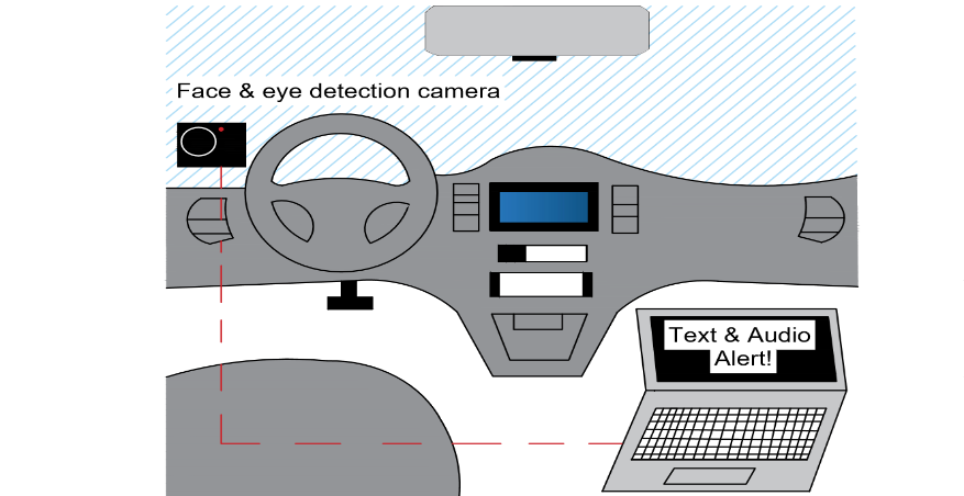 Figure 1. Proposed Eye-tracking System Sketch
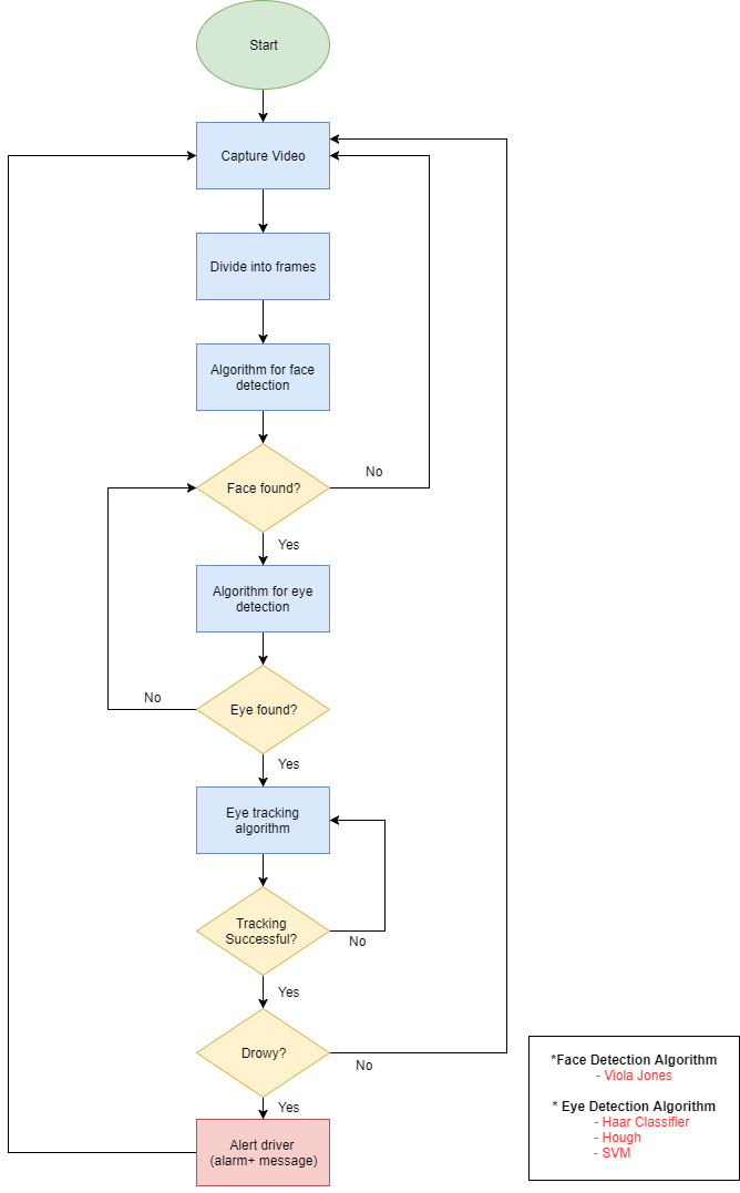 Figure 2. Flow-chart of the eye-tracking process
5. System Components
The proposed system consists of a high-resolution camera, an LCD, a speaker, and a microprocessor. The screen to be placed on the dashboard to the right-hand side of the driver. The camera will be positioned on the dashboard to the left-hand side of the driver and will be fixed by a camera holder. To start the system, the camera will be continuously recording a video of the driver and this video will be analyzed on PC initially then replaced by microprocessor later. The analysis will be done through many algorithms to detect the eyes of the driver. When the driver seems drowsy or distracted, the system will show an alert on the display screen among with a sound alert. Figure 2 shows the proposed design in a form of sketch for the system. The system flow chart that need to be implemented is explained in the flow chart. The real-time camera will stream an online video. An eye-tracking algorithm can be used to extract the features of the eyes. The classifier will play a role in the detection of open/close of the eye.
6. Design Specifications
The design of the real-time eye tracking is implemented to be an added-on solution that can fit in any vehicle. The purpose of the system is to alert the driver in case of drowsiness and distraction. The system will alert the driver as precaution event. In emergency cases, the system should interact with the vehicle and take over the control. This system is an added value to the wearable bracelet that couldn’t detect the sleepiness and distraction.
6.1. High Level Design
A simulator cockpit is designed and implemented in a professional way for testing the system. A steering wheel among with pedals are developed in an ergonomic way to simulate driving scenarios on road.
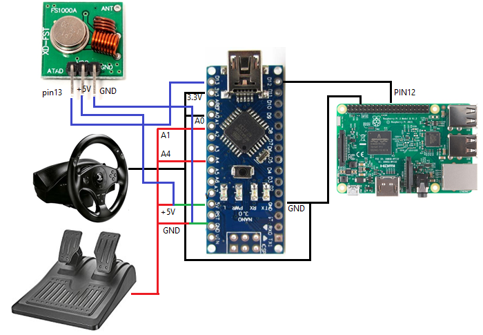 Figure 3. Connection of Raspberry Pi and Arduino Nano (Steering wheel)
6.2. Low Level Design
For the Low-Level design, the connections are made with Arduino and Raspberry Pi (see Error! Reference source not found.). The Raspberry Pi pin 12 is connected to the input pin 12 of the Arduino Nano that is attached to the steering wheel. In addition, the RF transmitter, the steering wheel and the pedals are all connected to the Arduino Nano as shown. The RF communication module is used to overcome the delay problem that happened when the control signals sent via Bluetooth. An Arduino Uno is attached to the rover (see Error! Reference source not found.), which shows the connection of the RF receiver, the LED, used to show that the rover is moving in autonomous mode, and the push button that the user must press to return to manual driving.
7. System Hardware Specifications
7.1. Camera
The Camera used in detection of the eye open/close is Logitech C290. The specifications of the camera are presented in Table 2. The most important factor in selecting the camera is the number of frames that the camera can capture in one second. For this camera is 30 frames per second (fps).
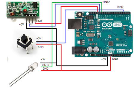 Figure 4. Connections of Arduino Uno (Rover)
Table 2. Specifications of the Camera
| Device Type | Web camera |
| Connectivity Technology | Wired |
| Digital Video Format | Colour |
| Max Digital Video resolution | H.264 |
| Features | 1080p Full HD movie recording, |
| Battery | None |
| Audio support | Yes |
| Computer interface | USB 2.0 |
| OS required | Microsoft Windows 7, Microsoft Windows Vista, Microsoft Windows XP SP3 or later |
| Connector type | 4 pin USB Type A |
Table 3. Raspberry Pi3 Specs
| SoC | BCM2837 |
| CPU | Quad Cortex A53 @ 1.2GHZ |
| Instruction set | ARMv8-A |
| GPU | 400MHz VideoCore IV |
| RAM | 1 GB SDRAM |
| Storage | Micro-SD |
| Ethernet | 10/100 |
| Wireless | 802.11n/ Bluetooth 4.0 |
| Video Output | HDMI/ Composite |
| Audio Output | HDMI / Headphone |
| GPIO | 40 |
7.2. Raspberry Pi 3
Raspberry Pi 3 Is a tiny credit card size computer. Just add a keyboard, mouse, display, power supply, micro SD card with installed Linux Distribution and you’ll have a fully-fledged computer that can run applications from word processors and spreadsheets to games.
7.3. Display & Audio 1280×800 IPS Screen
This screen has excellent resolution (1280×800) and IPS display so it is bright, crisp and looks good from any angle. This Screen even has HDMI audio support and can drive two 4-ohm speakers directly.
Table 4. IPS Screen Specs
| Dimensions of Screen | 105mm x 160mm x 3mm / 4.1″ x 6.3″ x 0.1″ |
| Weight of Screen | 91g |
| Power of Screen | 9 VDC |
| Display Ratio | 16:10 |
| Resolution | 1200 x 800 |
| Visible Area | 150mm x 95mm 16:10 |
| Display Dimensions | 162mm x 104mm x 4mm (6.4″ x 4.1″ x 0.2″) |
| Brightness | 400cd/m2 |
| Contrast | 800:1 |
| Display | HSD070PWW1 |
| Weight | 290g/10.2oz |
| HDCP | None |
8. Image Processing
For implementation of the system. A simulation of the eye tracking system is done using PC. The software used is OpenCV. For face and eye detection using Viola Jones and Haar Cascade Classifier algorithms were applied. The idea is to detect eyes are open or closed. When the eyes were closed, the system attempted to alert by showing a display message and sound. After the proof of concept, Raspberry Pi board as a main Processor for the system replaces the PC.
The basic idea of detecting the state of the driver revolves around the detection of the eyes. The recent advancement in the image-processing field, there are now multiple real-time methods that could enable the detection and tracking of multiple objects. Bag-of-Words models, Histogram-of-oriented gradients (HOG), Deformable Parts Models, Exemplar models and Viola-Jones are some of the widely used methods for object detection.
Viola-Jones method is one of the most widely used method of object detection. The main feature that makes this method so popular is its ability training is slow but detect fast. Haar basis feature filters are used in this algorithm avoiding, thus avoiding multiplications.
Detection happens inside a detection window. The minimum and maximum window size is selected, and for each size a sliding step size is selected. The detection window moves across the selected image as follows:
Cascade -connected classifiers contained inside each face recognition filter. The classifier takes care of scanning at a rectangular subset of the detection window and recognize if it looks like a face or not. The next classifier is applied in case the face detected on the off chance that all classifiers give a positive answer, at that point the filter gives a positive answer and the face is perceived. If nothing detected, the next filter in the set of N filters should execute.
Each classifier is composed of Haar feature extractors (weak classifiers). Each Haar feature is the weighted sum of 2-D integrals of small rectangular areas attached to each other. The weights may take values ±1. Haar feature extractors are scaled with respect to the detection window size.
Viola-Jones algorithm consists of four stages, Haar features, integral image, AdaBoost, and cascade. To begin with, Haar features detection can be summarized in three steps. First, convert the colored, RGB, images to grey-scale images. Then, integral images are generated. The integral image is a summation of the pixel values of the original image. The summation of the pixels are calculated by choosing a coordinate (x,y) and summing all the values to the top-left of the point including the point itself. Second, different levels of integral images are used to obtain the Haar wavelets. Haar-like features are a combination of two or more rectangles that have different contrast; they can be two-rectangle, three-rectangle, or four-rectangle, and so on. The third step is the AdaBoost, which is an algorithm that looks at relevant features and is used to detect objects, in this case the face and eye. When the features are extracted, a stage comparator will sum all the features and compares them with the threshold. After these steps are done, there is the cascade step; and in this step the stages are cascaded to eliminate any non-face candidates to improve the computation time an accuracy of the detection.
8.1. Algorithm Implementation
The Algorithm is applied sequential. The first step is to detect the face. If no faces detected, this means that the driver is looking to the right or left or down. A counter start counting, and an alert message is sent after 1 second. If faces detected, then the algorithm will extract the eyes from the face. If the driver’s eyes opened don’t count any values. In case the driver closed his eyes then a counter start counting based on the required timing. After that time an alert message is sent to driver’s. Figure 5 shows the application of the algorithm as a simulation of a detected eye.
9. Results
Real-time Eye tracking came up as an added-solution to the wearable biosensors bracelet. This solution helps in an accurate real-time monitoring of the driver’s eyes while driving. This system aims to assist the driver not only in case of drowsiness and in case of Fatigue; it can assist in case of driver’s distraction due to changing radio stations, chatting with passengers or texting while driving.
The system implemented as a cockpit for testing in-door to validate the system. The system is installed and tested in a real-vehicle to proof the correctness of the proposed system.
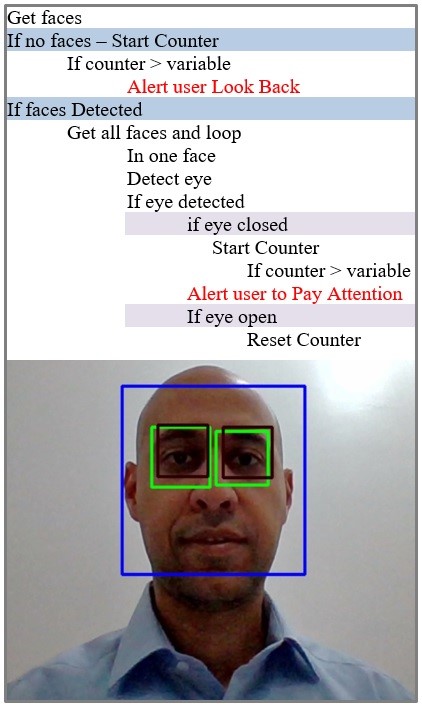 Figure 5. Eye Detection using Viola-Jones Algorithm
9.1. Indoor-System Test
The High-Level design of the simulator shown below (see Error! Reference source not found.), where the driver is seated in front of the steering wheel. The steering wheel gives the subject the feeling of controlling a vehicle. The driver is facing a camera and the display screen. In addition, there are pedals that control the rover when the driving mode is manual. One pedal is used to move the car forward and the other one moves it backwards.
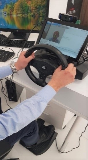 Figure 6. Simulator Cockpit Design
The system tested in-door on 20 persons to record a small data-set for analysis and validation of the system. The system will be coupled to the prototype explained earlier, where the driver sat down in front of the steering wheel and imitated distraction or sleepiness as shown in figure. 6. The subject is controlling the robotics rover as he/she is driving a vehicle on roads. In case the user is distracted for 1.5 seconds (pre-set value), the system will respond by a message on the screen Look back! Moreover, the system reacts by switching the rover mode to autonomous in which the rover will run obstacle avoidance algorithm as a simulation of cars and obstacles on roads. In case, the subject closed his/her eyes for 1 second (pre-set value), the system will react by switching the rover mode to autonomous mode.
The recorded data of the subjects for in-door testing is shown in Table 5 and the graph is shown below (see Error! Reference source not found.). The results of average correct detection rate are 82 %. This result is very promising to test the system in real vehicle.
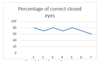 Figure 7. Correct Detection Percentage
Table 5. In-door Real-time Eye tracking Recorded Data
| Index | Age | Gender | Samples | Correct Detections | False Detections | Percentage | |
| 1 | 20 | M | 10 | 8 | 2 | 80 | |
| 2 | 23 | M | 10 | 7 | 3 | 70 | |
| 3 | 26 | M | 10 | 8 | 2 | 80 | |
| 4 | 21 | M | 10 | 9 | 1 | 90 | |
| 5 | 36 | M | 10 | 10 | 0 | 100 | |
| 6 | 25 | M | 10 | 7 | 3 | 70 | |
| 7 | 45 | M | 10 | 7 | 3 | 70 | |
| 8 | 36 | M | 10 | 8 | 2 | 80 | |
| 9 | 24 | M | 10 | 9 | 1 | 90 | |
| 10 | 62 | M | 10 | 10 | 0 | 100 | |
| 11 | 45 | F | 10 | 8 | 2 | 80 | |
| 12 | 52 | F | 10 | 7 | 3 | 70 | |
| 13 | 42 | F | 10 | 9 | 1 | 90 | |
| 14 | 35 | F | 10 | 10 | 0 | 100 | |
| 15 | 26 | F | 10 | 7 | 3 | 70 | |
| 16 | 29 | F | 10 | 8 | 2 | 80 | |
| 17 | 27 | F | 10 | 7 | 3 | 70 | |
| 18 | 28 | F | 10 | 8 | 2 | 80 | |
| 19 | 39 | F | 10 | 7 | 3 | 70 | |
| 20 | 34 | F | 10 | 10 | 0 | 100 | |
| Average Correctness | 82 | ||||||
9.2. Out-door System Test
The system is installed in two different car models for real driving conditions testing as shown in below (see Error! Reference source not found.). Once, the system detects eye-closing for 1 second (pre-set value) or distraction detection for 1.5 second (pre-set value) an audible alert sound among with alert message sent to the user for driver’s assistance on road.
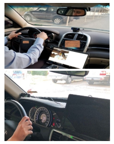 Figure 8. Installation of the System in real-vehicles
The system tested on seven subjects. The testing scenario is to drive the car at speed around 40-50 Km/hr. The driver will act based on the assistant instructions. The assistant task is to direct the driver to close eye or distract the eyes by looking right/left and record the data of correct detection to validate the algorithm and system on roads. The recorded data is shown in Error! Reference source not found. and the results of average correct detection rate of closed eyes is 72.8 % with an average correct detection rate of distracted eyes of 67.14 % as shown below (see Error! Reference source not found.).
As noticed, the results of correct detection reduced compared to the in-door test results. The reasons of this decrease are that the car on the streets is exposed to different lighting conditions that needs a pre-setting. Also, the driver movements in the real-driving conditions increases which needs higher frame rate of camera.
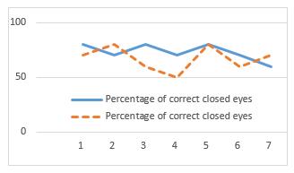 Figure 9 Correct Detection of eye closed and distracted eyes in out-door testing environment
Table 6. Out-door Real-time Eye tracking Recorded Data
| Index | Age | Gender | Samples | Correct Detections of closed eyes | Correct Detections of Distracted eyes | Percentage of correct closed eyes | Percentage of correct distracted eyes | |
| 1 | 30 | M | 10 | 8 | 7 | 80 | 70 | |
| 2 | 25 | M | 10 | 7 | 8 | 70 | 80 | |
| 3 | 21 | F | 10 | 8 | 6 | 80 | 60 | |
| 4 | 22 | F | 10 | 7 | 5 | 70 | 50 | |
| 5 | 24 | F | 10 | 8 | 8 | 80 | 80 | |
| 6 | 20 | F | 10 | 7 | 6 | 70 | 60 | |
| 7 | 22 | F | 10 | 6 | 7 | 60 | 70 | |
| Average Correctness | 72.857143 | 67.142857 | ||||||
The system testing out-door is shown below (see Error! Reference source not found.). The system is tested with the PC to record the system test in out-door environments. The system is validated, and the results were promising to improve the algorithm for more scenarios.
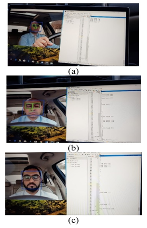 Figure 10. (a) Distracted driver, (b) closed eyes driver, (c) closed eyes driver
10. Conclusion
The complete system is implemented with a developed simulator cockpit for in-door system validation and data collection purposes. The measured average correct detection of the system is 82 %. This system is tested in subjects in average of 33 years old and showed no issues regarding the age. It is valid for people wearing eyeglasses without any problem. In out-door environment, the results of average correct detection rate of closed eyes are 72.8 % with an average correct detection rate of distracted eyes of 67.14 %.
11. Future Works
- The system can’t detect during night due to lack of camera version
- The response time of the system when the driver closes his/her, eyes should be a function of vehicle speed.
- The system should be adapted to the looking of mirrors scenario.
- Sensor fusion of the camera with all the wearable biosensors.
- Use Night-vision camera to detect the eyes at night.
- Use better specifications camera will increase the efficiency of the system
- https://www.nhtsa.gov/, 4/2017.
- “Kuwait Times,” 15 10 2017. [Online]. Available: http://news.kuwaittimes.net/website/.
- Sherif Said ; Samer AlKork ; Taha Beyrouthy ; M Fayek Abdrabbo, “Wearable bio-sensors bracelet for driveras health emergency detection,” in Biosmart ,IEEE, Paris, France, 2017.
- Singh Himani parmar ; Mehul Jajal ; Yadav priyanka Brijbhan, “Drowsy Driver Warning System Using Image Processing,” Nternational Journal Of Engineering Development And Research , 2017.
- “http://www.who.int,” 2016. [Online].
- Llerena, L.E.; Aronow, K.V.; Macleod, J.; Bard, M.; Salzman, S.; Greene, W.; Haider, A.; Schupper, A. J. , “ An evidence-based review: Distracted driver.,” Trauma Acute Care Surg., vol. 78, p. 147–152, 2015.
- Bennakhi, A.; Safar, M. , “Ambient Technology in Vehicles: The Benefits and Risks,” Procedia Comput. Sci., vol. 83, pp. 1065-1063, 2016.
- Liu, T.; Yang, Y.; Huang, G.B.; Lin, Z, “Detection of Drivers’ Distraction Using Semi-Supervised Extreme Learning Machine,” in In Proceedings of ELM-2014; Springer, Berlin, Germany, 2015.
- Simons-Morton, B.G.; Guo, F.; Klauer, S.G.; Ehsani, J.P.; Pradhan, A.K, “Keep your eyes on the road: Young driver crash risk increases according to duration of distraction,” J. Adolesc. Health, vol. 54, p. S61–S67, 2014.
- Recarte, M.A.; Nunes, L.M., “ Mental workload while driving: Effects on visual search, discrimination, and decision making,” J. Exp. Psychol. Appl. , vol. 9, pp. 119-137, 2003.
- Klauer, S.G.; Guo, F.; Simons-Morton, B.G.; Ouimet, M.C.; Lee, S.E.; Dingus, T.A, “Distracted driving and risk of road crashes among novice and experienced drivers,” N. Engl. J. Med., vol. 370, p. 54–59, 2014.
- Bergmark, R.W.; Gliklich, E.; Guo, R.; Gliklich, R.E. , “Texting while driving: The development and validation of the distracted driving survey and risk score among young adults.,” Inj. Epidemiol., 2016.
- Xia Liu, “Real-time eye detection and tracking for driver observation under various light conditions,” Intelligent Vehicle Symposim, 2002.
- Grace, “Drowsy driver monitor and warning system,” in Proc. Int. Driving Symp. Human Factors in Driver Assessment, Training andVehicle Design, 2001.
- G. Yuan, “A real-time eye detection system based on the active IR illumination”.
- Eriksson, and N.P. Papanikotopoulos M., “Eye-tracking for detection of driver fatigue,” Proc .Int. Conf. Intelligent Transportation Systems, pp. 314-318, 1997.
- Singh, and N.P. Papanikolopoulo S., “Monitoring driver fatigue using facial analysis techniques,” in Proc. Int. Conf. Intelligent Transportation Systems, Tokyo, 1999.
- Hyungkeun Jee, Kyunghee Lee, and Sungbum Pan, “Eye and Face Detection using SVM,” in Proceedings of the 2004 Intelligent Sensors, Sensor Networks and Information Processing Conference, Melbourne, Australia, 2005.
- Jay D. Fuletra ; Viral Parmar, “Intelligent Alarm System for Dozing Driver using Hough transformation,” IJEDR, vol. 2, no. 2, pp. 2797-2800, 2014.
- Anirban Dasgupta, Anjith George, S. L. Happy, and Aurobinda Routray, “A Vision-Based System for Monitoring the Loss of Attention in Automotive Drivers,” IEEE TRANSACTIONS ON INTELLIGENT TRANSPORTATION SYSTEMS, vol. 14, no. 4, 2013.
- Hari Singh ; Jaswinder Singh, “Human Eye Tracking and Related Issues: A Review,” International Journal of Scientific and Research Publications, vol. 2, no. 9, 2012.
- Mitharwal Surendra Singh L. ; Ajgar Bhavana G. ; Shinde Pooja S. ; Maske Ashish M. , “EYE TRACKING BASED DRIVER DROWSINESS MONITORING AND WARNING SYSTEM,” International Journal of Technical Research and Applications, vol. 3, no. 3, pp. 190-194, 2014.
- Onken, “DAISY: an adaptive knowledge-based driver monitoring and warning system,” in Proc. Vehicle Navigation and Information Systems Conf., 1994.
- Fletcher, N. Apostoloff, L. petersson, and A. Zelinsky, “Vision in and out of Vehicles,” IEEE Trans. Intelligent Transportation Systems, pp. 12-17, 2003.
- F Sayegh, F Fadhli, F Karam, M BoAbbas, F Mahmeed, JA Korbane, S AlKork, T Beyrouthy “A wearable rehabilitation device for paralysis,” 2017 2nd International Conference on Bio-engineering for Smart Technologies (BioSMART), Paris, 2017, pp.1-4.