Omni-directional Dual-Band Patch Antenna for the LMDS and WiGig Wireless Applications

Adv. Sci. Technol. Eng. Syst. J. 3(6), 496–500 (2018);
 DOI: 10.25046/aj030658
In this paper an omnidirectional dual band monopole antenna at 28 GHz and 60 GHz which is fit for indoor and outdoor wireless applications is developed. The proposed antenna consists of two rectangular patches with a T folded patch. The design, analysis, and optimization processes through this article are executed by the numerical method, Finite Element Method (FEM) and verified with another numerical method, Finite integration Technique (FIT). Good agreement between the results by these two simulators is obtained. The proposed antenna has achieved dual bands with omnidirectional patterns. The first band at 28 GHz is extended from 27.5 GHz to 28.958 GHz with 5.1 % bandwidth and total efficiency of more than 93% along the entire band which serves the LMDS band. The second band at 60 GHz is extended from 45.2 GHz to 84.4 GHz which serves the WiGig band with bandwidth of 60.6% and total efficiency of 85.5% along the entire band. The proposed antenna performance makes it a good candidate for the fifth generation (5G) applications.
1. Introduction
This paper is an extension of work originally presented in ACES [1]. More analysis and parametric studies have been done. The average data per person uses in telecommunication is rapidly increases over the past three decades [2]. This increase is more noticeable mostly with the outgrowth of the wireless communications. The main requirements for wireless communications are the ability to develop a low-cost, light-weight, and low-profile antennas to maintain good performance along a large bandwidth [2].
The shortage in the available global bandwidth has stimulated the reconnaissance of the under-utilized millimeter wave frequency band for the future wireless communications [3].
Multiband antennas have massive applications in millimeter band applications. A various techniques in the literature have been developed for multiband microstrip antennas as in [4–12]. For instance, a multilayer GaAs is described in [4] to achieve a multiband antenna operating at 35 GHz. In [5], two bands with less than 1.2% bandwidth with gains of -9 dBi and 1 dBi at 24 GHz band and 60 GHz band respectively is presented. A dual band antenna at 41 GHz / 52.2 GHz using a meta-resonator with pair of split ring resonators is introduced in [6] with bandwidth of 2 %, gain of 3.76 dBi, and efficiency of 71%. In [7], two different modes are obtained to get a dual band at 58 GHz and 77 GHz with gains of -2 dBi and 0.3 dBi, respectively. The achieved bandwidths at both bands are nearly 6%. A dual band centered at 24.5 and 35 GHz has been presented in [8] with only 1% bandwidth and less than 2.8 dBi gain using liquid crystal polymer. A coplanar hybrid dual band antenna at 83 GHz / 94 GHz with a slot in feeding line has been developed in [9]. In [10] an antenna array with Electromagnetic Band Gap [EBG] structure was used to develop a dual band at 28 / 38 GHz with bandwidth of less than 5.8%. A three layers of substrates have been used in [11] to design a Fabry-Perot cavity antenna operates at 36 GHz with high gain. In [12], L-shaped slots have been used to obtain a dual band 28 / 38 GHz slotted patch antenna.
In this paper, the design, optimization, and simulation of a monopole planar antenna are introduced. The antenna is optimized to operate at Ka _ band (28 GHz) for Local Multipoint Distribution Service (LMDS) which currently investigated for the fifth generation mobile cellular [13], and the V _ band (60 GHz) for Wireless Gigabit Alliance (WiGig) applications [14].
This paper is organized into four sections. Section 1 covers the introduction and literature review. Antenna structure and design is introduced in section 2. Parametric study of a dual band omnidirectional pattern circularly polarized wideband antenna is presented in section 3. The simulation results are investigated in Section 4. Finally, the conclusion is presented in section 5.
2. Antenna Geometry and Design
Figure 1 shows the antenna geometry in perspective and top view. The proposed antenna patch consists of a T-folded shape with two rectangular patches and partially grounded [15]. The antenna gives wide bandwidth with improved antenna performance. The patch mounted on substrate FR-4 with a relative permittivity of 4.4. Figure 2 illustrates the whole antenna dimensions. The substrate dimension is Ws by Ls and the partial ground is Ws by Lg. The dimensions of T-folded are Ltop, Lfold , Lt Wt for top length, folded side length, mid length, and mid width. The two patches have dimensions of Wp by Lp.
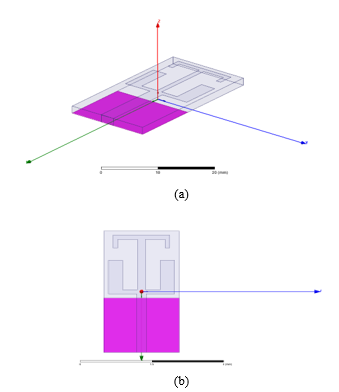 Figure1. Antenna geometry a) Perspective view b) Top view.
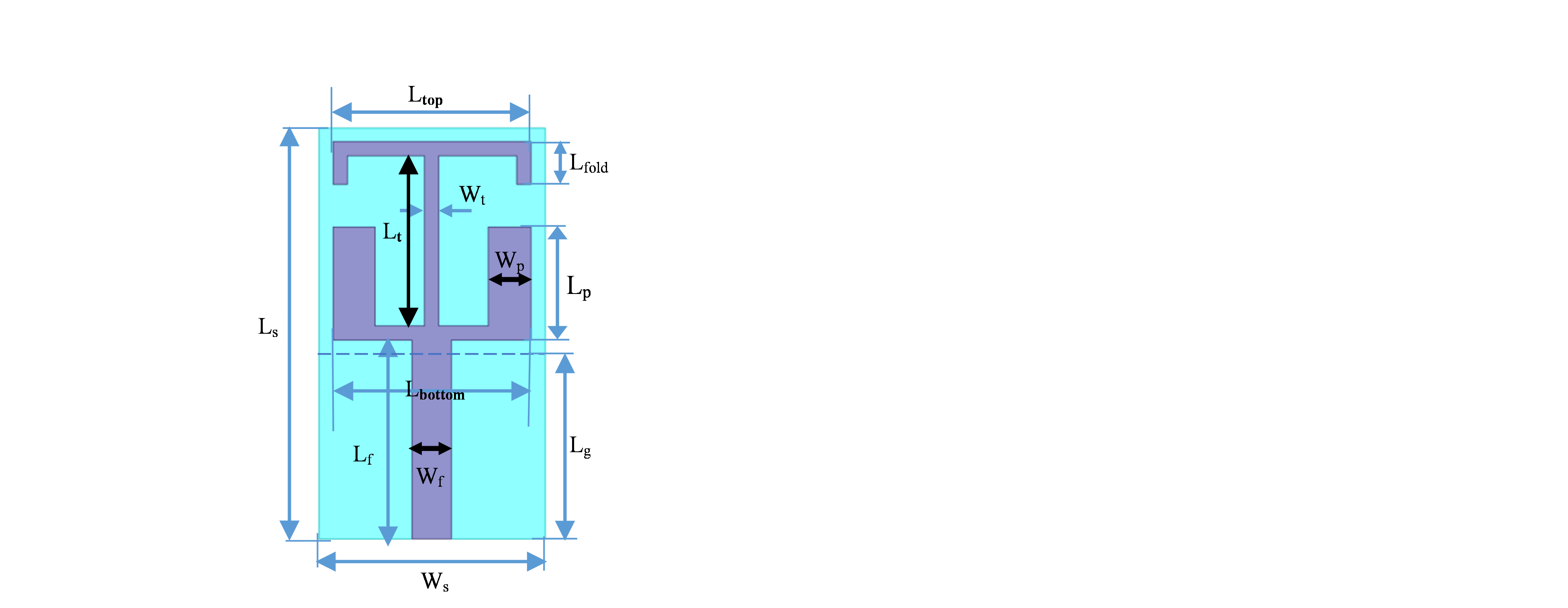 Figure 2. Antenna structure and dimensions.
The antenna feeding transmission line (TL) dimension is Wf by Lf. The TL characteristic impedance can be calculated by the following formulas [16]:
When , the characteristic impedance is
 In the formulas, h represents the substrate height, w represents the TL width, and represents the effective relative permittivity.
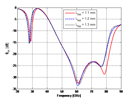 Figure. 3. The effect of changing Ltop on S11.
3. Parametric Study
The effect of varying antenna dimensions Lfold, Ltop, Lbottom, LP, WP, and Lt using HFSS are shown in figures 3 to 8. The dimensions of the substrate, ground, and feeder are kept unchanged. With increasing Ltop of the horizontal part of T-shaped, the lower resonant frequency is decreased with same bandwidth whereas the upper bandwidth is decreased as shown in Figure 3. Figure 4 illustrates the effect of varying Lbottom on the return loss. As noted from the figure, by increasing the Lbottom, the lower resonant frequency almost unaltered whereas the resonant frequency of the upper band is increased with a little increase in the bandwidth. With increasing WP, the upper and the lower resonant frequencies are almost unchanged as shown in Figure 5.
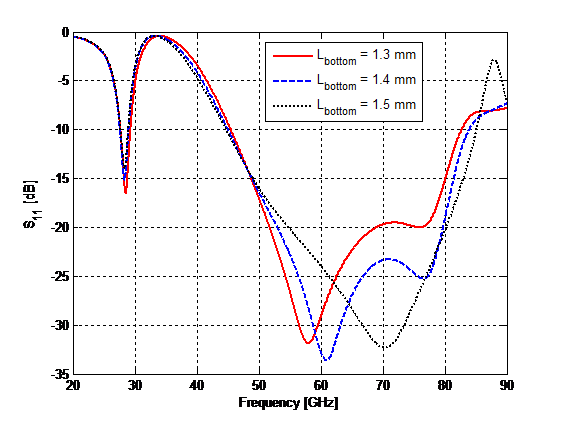 Figure. 4. The effect of changing Lbottom on S11.
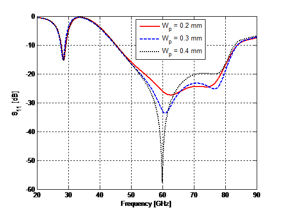 Figure. 5. The effect of changing Wp on S11.
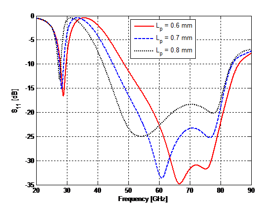 Figure. 6. The effect of changing Lp on S11.
As the length of rectangular patch LP increases, the upper and lower resonant frequency are decreased but the antenna matching becomes worse. Lower bandwidth is increases whereas the upper bandwidth is decreases as shown in Figure 6. Figure 7 illustrates the return loss varies with Lfold. As Lfold increases the lower resonant frequency decreases while upper resonant frequency unchanged whereas the lower bandwidth is not affected, the upper bandwidth is a little decreases as shown in Figure 7. With increasing Lt, the lower and the upper resonant frequencies are not affected whereas the upper bandwidth is decreases, the lower bandwidth is unchanged as shown in Figure 8.
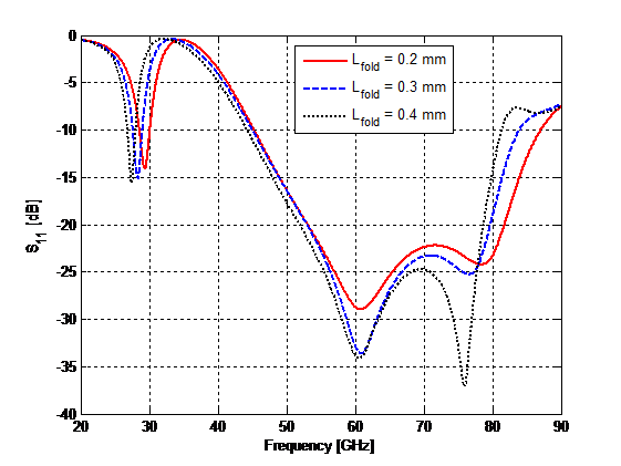 Figure. 7. The effect of changing Lfold on S11.
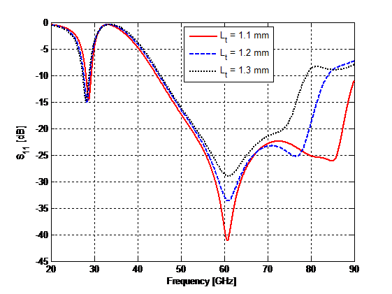 Figure. 8. The effect of changing Lt on S11.
4. Antenna Simulation Results
The antenna dimensions are optimized to obtain an Omni-directional radiation patterns with acceptable performance at 28 GHz and 60 GHz. Table 1 contains the optimized dimensions for the proposed antenna in order to have a dual band.
The optimized antenna is simulated using two simulators based on FIT [17] and FEM [18] in order to validate the results. The S11 for the proposed antenna using FEM and FIT is shown in Figure 9. The FEM gives a better matching than FIT and the small deviation in the 60 GHz band is due to the different mesh sizes. As can be noted from Figure 9, the antenna well matched over the two bands and the impedance bandwidth for which S11 ≤ -10 dB in 28 GHz band is extended from 27.52 GHz to 28.96 GHz which serves the LMDS band and in 60 GHz band is extended from 45.2 GHz to 84.4 GHz which serves the WiGig band.
Table 1: Dimensions of the proposed antenna in mm.
| Parameter | Value | Parameter | Value |
| Ws | 1.6 | Wp | 0.3 |
| Ls | 2.9 | Lp | 0.7 |
| Lg | 1.3 | Wt | 0.1 |
| Wf | 0.2 | Lt | 1.2 |
| Lf | 1.4 | Ltop | 1.2 |
| Lfold | 0.3 | Lbottom | 1.4 |
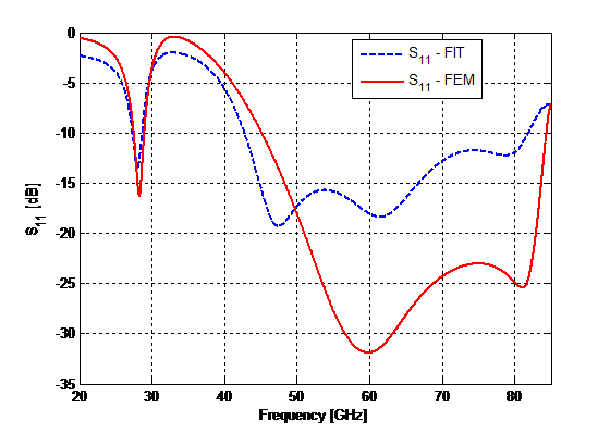 Figure. 9. Comparison of S11 for the optimized antenna by FIT and FEM.
The antenna resonates at 28.24 GHz with 1.44 GHz bandwidth (5.1 %) and at 64.76 GHz with wide bandwidth of 39.24 GHz (60.6%). The VSWR is shown in Figure 10 with VSWR ≤ 2 using FIT and FEM in the entire bandwidths of both bands.
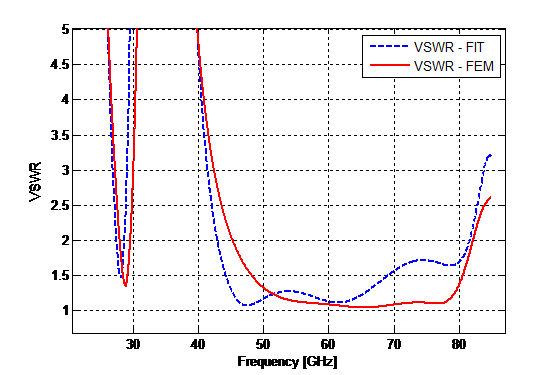 Figure. 10. VSWR using FIT and FEM.
The antenna real and imaginary input impedance for the proposed antenna is illustrated in Figure. 11. As can be noted from Figure 11, the antenna is well matched to 50 Ω TL since the real part of the input impedance is approximately 50 Ω while the imaginary part tends to zero along the entire bandwidths of both bands.
The radiation patterns at 28 GHz and 60 GHz are illustrated in Figure 12. The directivity pattern at 28 GHz with Do of
2.28 dBi is illustrated in Figure 12(a) and at 60 GHz with Do of 3.41 dBi is shown in Figure 12(b). The total antenna efficiency along the lower band is 93 % while along the upper band is
85.5 %.
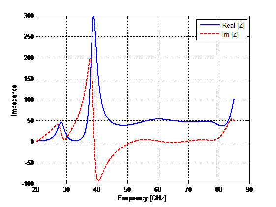 Figure. 11. The real and imaginary part of input impedance for the proposed antenna.
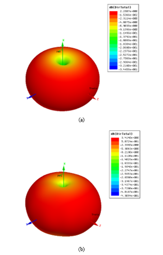 Figure 12. The directivity patterns at a) 28 GHz (Do = 2.28 dBi) and at b) 60 GHz (Do = 3.4 dBi).
5. Conclusion
In this paper, antenna with two rectangular patches and a T-shaped folded patch is designed, optimized, and simulated. The antenna exhibits two bands resonate at 28.24 GHz and 64.76 GHz with bandwidths of 1.44 GHz (5.1%), and 39.24 GHz (60.6%) respectively. The lower band (Ka-band) is suitable for LMDS while the upper band (V-band) with wideband is suitable for WiGig. The omnidirectional radiation pattern is obtained using partial ground plane with maximum directivities of 2.28 dBi and 3.414 dBi at the two bands respectively. The total efficiency along the entire lower and upper bands exceeds 85% which can be used in the fifth generation applications.
Acknowledgment
The author gratefully acknowledges the support of Prince Sultan University.
- M. S. Ibrahim, “Dual-band microstrip antenna for the fifth generation indoor/outdoor wireless applications,” in 2018 International Applied Computational Electromagnetics Society Symposium (ACES), 2018, pp. 1-2.
- S. S. Jaco du Preez, Millimeter-Wave Antennas: Configurations and Applications: Springer International Publishing Switzerland, 2016.
- T. S. Rappaport, S. Sun, R. Mayzus, H. Zhao, Y. Azar, K. Wang, G. N. Wong, J. K. Schulz, M. Samimi, and F. Gutierrez, “Millimeter Wave Mobile Communications for 5G Cellular: It Will Work!,” IEEE Access, vol. 1, pp. 335-349, 2013.
- D. Sanchez-Hernandez, Q. H. Wang, A. A. Rezazadeh, and I. D. Robertson, “Millimeter-wave dual-band microstrip patch antennas using multilayer GaAs technology,” IEEE Transactions on Microwave Theory and Techniques, vol. 44, pp. 1590-1593, 1996.
- H. Jie-Huang, W. Jin-Wei, C. Yi-Lin, and C. F. Jou, “A 24/60GHz dual-band millimeter-wave on-chip monopole antenna fabricated with a 0.13-µm CMOS technology,” in 2009 IEEE International Workshop on Antenna Technology, pp. 1-4, 2009.
- I. K. Kim and V. V. Varadan, “Electrically Small, Millimeter Wave Dual Band Meta-Resonator Antennas,” IEEE Transactions on Antennas and Propagation, vol. 58, pp. 3458-3463, 2010.
- T. Y. Lin, T. Chiu, and D. C. Chang, “Design of Dual-Band Millimeter-Wave Antenna-in-Package Using Flip-Chip Assembly,” IEEE Transactions on Components, Packaging and Manufacturing Technology, vol. 4, pp. 385-391, 2014.
- D. Lee and C. Nguyen, “A millimeter-wave dual-band dual-polarization antenna on liquid crystal polymer,” in 2014 IEEE Antennas and Propagation Society International Symposium (APSURSI), pp. 775-776, 2014.
- S. Agarwal, N. P. Pathak, and D. Singh, “Concurrent 83GHz/94 GHz parasitically coupled defected microstrip feedline antenna for millimeter wave applications,” in 2013 IEEE Applied Electromagnetics Conference (AEMC), pp. 1-2, 2013.
- N. Ashraf, O. Haraz, M. A. Ashraf, and S. Alshebeili, “28/38-GHz dual-band millimeter wave SIW array antenna with EBG structures for 5G applications,” in 2015 International Conference on Information and Communication Technology Research (ICTRC), pp. 5-8, 2015.
- G. N. Tan, X. X. Yang, and B. Han, “A dual-polarized Fabry-Perot cavity antenna at millimeter wave band with high gain,” in 2015 IEEE 4th Asia-Pacific Conference on Antennas and Propagation (APCAP), pp. 621-622, 2015.
- H. Aliakbari, A. Abdipour, R. Mirzavand, A. Costanzo, and P. Mousavi, “A single feed dual-band circularly polarized millimeter-wave antenna for 5G communication,” in 2016 10th European Conference on Antennas and Propagation (EuCAP), pp. 1-5, 2016.
- S. Hur, S. Baek, B. Kim, Y. Chang, A. F. Molisch, T. S. Rappaport, K. Haneda, and J. Park, “Proposal on Millimeter-Wave Channel Modeling for 5G Cellular System,” IEEE Journal of Selected Topics in Signal Processing, vol. 10, pp. 454-469, 2016.
- C. J. Hansen, “WiGiG: Multi-gigabit wireless communications in the 60 GHz band,” IEEE Wireless Communications, vol. 18, pp. 6-7, 2011.
- W. H. Yang J., Lv Z., Wang H., “Design of miniaturized dual-band microstrip antenna for WLAN application,” Sensors, vol. 16, pp. 1-15, 2016.
- C. A. Balanis, Advanced Engineering Electromagnetics, Second Edition ed.: JohnWiley & Sons, New York, 2012.
- (2015) CST Microwave Studio. Available: https://www.cst.com/products/cstmws
- High Frequency Surface Structure (HFSS) (15 ed.). Available: http://www.ansys.com