Design of an Additively Manufacturable Multi-Material Light-Weight Gripper with integrated Bellows Actuators

Adv. Sci. Technol. Eng. Syst. J. 4(2), 23–33 (2019);
 DOI: 10.25046/aj040204
Combining state-of-the-art additive manufacturing technologies with structural optimization has the potential to produce geometrically complex multi-material components with integrated functionalities and desired structural behavior. In this article, the simulation-driven design process of a multi-material light-weight gripper with an integrated pneumatic bellows actuator is described. The design of the bellows structure is based on a previously published contribution to the RoboSoft2018 conference in Livorno, Italy. The conference paper contains the shape optimization and experimental investigations of the structural and fatigue behavior of linear type multi-material PolyJet bellows actuators. In this extended version, the main findings of the conference paper are translated into the design of a rotary type bellows actuator that is finally integrated into a multi-material light-weight gripper. In order to define the lay-out of the gripper’s support structure, a density-based topology optimization is performed and the application on a PolyJet printed light-weight robot is demonstrated. The presented design approach and results are useful for researchers and engineers involved in the development of multi-material additive manufacturing, simulation-driven design and functionally integrated structures for pneumatic robotic systems.
1. Introduction
Recent advances in material science and manufacturing technologies allows for the production of geometrically complex [1], [2] multi-material structures that were not manufacturable until recently [3]. At the same time, an increasing demand for short lead times, large product variety and flexible production processes will influence the design of future robotic systems. Particularly interesting components for future light-weight robots may result from the combination of multi-material additive manufacturing (AM) and pneumatic actuation.
1.1. “Low Inertia and Compliant Elements” Approach
An approach for increased flexibility in future production processes is to combine human and robotic strengths in human-robot collaboration scenarios. The associated abolition of safety cages—that typically enclose robot workspaces today—leads to alternative safety concepts. In general, various measures can be applied to reduce the severity of injuries or damage caused by an unintended collision [4]. Thereby, the addition of compliant elements to the kinematic chain and the reduction of manipulator link inertia contributes to an inherently safe design [4], [5]. In the described work, novel materials and manufacturing technologies are combined with structural optimization to create compliant and light-weight components for light-weight robots.
1.2. Topology Optimization and Additive Manufacturing
The term topology optimization (TO) covers mathematical methods that allow for the definition of an optimum material distribution (also “material lay-out” [6]) within a given design space. Typical optimization set-ups are the minimization of structural compliance (or “global stiffness”, [6]) with a constraint volume or the minimization of used material (volume) respecting a stress constraint. The underlying concept and fundamentals of todays TO have already been proposed in the 1990s (see [7], [8]). However, the field of TO has recently attracted a lot of attention. This actuality may (at least partly) be explained by an increasing degree of practical applicability of the optimization results through additive manufacturing of single material [9], [10], [11] as well as multi-material structures [3], [12]. Most AM processes allows for very complex geometries and therefore facilitate simulation-driven design processes. Thereby, light-weight design is especially relevant for robotic components close to the payload as their motion results in comparatively large inertial loads which in turn reduce the robot’s performance and safety. Hence, considering AM technologies for the development of robot components makes sense in many ways [13]. Moreover, users of optimization approaches based on a given material layout, such as shape optimization (SO) and sizing optimization [14], can as well benefit from the absence of conventional manufacturing constraints as a result of the layer-wise material deposition inherent to many AM technologies.
1.3. Pneumatic Bellows Actuators
As a result of high gear ratios, typical electro-mechanical drive systems show little compliance when subjected to abrupt external loadings. Against the background of human-robot collaboration, mechanical designs have been developed that overcome this behavior i.e. can reduce the stiffness of electro-mechanical drive systems by the addition of compliant elements between the motor and torque output [15]. The use of nonlinear springs even allows for adjustment of the stiffness level [16], [17] so that the compliance of the system can be tuned according to a specific application. However, these measures come along with an inevitable increase in weight and mechanical complexity. The use of pneumatic actuators presents an alternative approach. Due to the relatively low compression modulus of air, pneumatic actuators show inherently compliant behavior and can easily be arranged to antagonistic pairs with adjustable compliance [17], [18], [19]. However, conventional pneumatic actuators (e.g. pneumatic cylinders) include dynamic seals and require smooth surfaces and close manufacturing tolerances [20]. Considering AM for the production of pneumatic actuators,lternative concepts such as bellows actuators are more promising. The structural behavior of bellows actuators can easily be modified by shape and material variations. Bellows actuators have been realized by various AM technologies such as selective laser sintering [21], PolyJet™ printing [20], [22] and Digital Mask Projection Stereolithography [23]. Numerous publications demonstrate the silicone molding process of bellow-like bending actuators utilizing additively manufactured molds (e.g. [24]). Also, detailed reviews of bellows actuators in the context of articulated robotic systems [25], 3D printing [26] and soft robotics [27] have been published. In continuum manipulators such as the “Bionic Handling Assistant” [21], bellows structures are not only used for actuation but also as a support structure.
1.4. The DIMAP Project
The main objective of the EU founded research project “Digital Materials for 3D Printing” (DIMAP) was the development of novel functional materials for PolyJet™ technology (http://www.dimap-project.eu). In PolyJet™ printing, three-dimensional objects are created from layers of small droplets of resin that are cured via ultra-violet light. Using this technology, multi-material structures with highly complex geometries can be manufactured. In order to narrow down the possible applications of the materials and technology in industry-like environments, a PolyJet-printable light-weight robot was developed.
1.5. Aim and Structure of this article
PolyJet™ printing is an interesting option for the manufacturing of highly geometrically complex and functionally integrated multi-material structures. These capabilities may be used to produce robotic components with desired structural behavior such as maximum stiffness (for light-weight structures) and inherent compliance (for actuators). Despite the existence of multiple examples of AM-related advanced structural optimization methods and multiple examples for AM of bellows structures, there is a lack of knowledge on the design and use of functional multi-material structures in industrial-near applications. This is especially the case for PolyJet™ printing. Thereby, the absence of sufficient knowledge on the achievable performance and sustainability [28] of PolyJet bellows actuators holds back the exploitation of the technological possibilities. The aim of this work is therefore to develop a complex pneumatic-mechanical multi-material component in the context of the development of a PolyJet printable light-weight robot for the DIMAP project. The chosen component is a multi-material light-weight gripper that comprises a geometrically complex bellows actuator and a numerically optimized light-weight structure. By means of the gripper development, structural and material properties are investigated, and suitable design strategies are proposed. With the final design and application to a functional light-weight robot an example is given that may inspire and encourage others for the application of the proposed materials, manufacturing technology and design approaches.
1.6. Design Approach and Concept
The structure of the gripper development is displayed in Figure 1. In a first step a conceptual design (A) is presented that already considers the functional principle of the gripper and adjacent construction in the robot. Moreover, standard parts (bearings, machined parts) are already defined at this stage. The further development is separated into the design of the bellows actuator and the support structure. This separation does not only take place on a component but also on a methodical level as the bellows actuator is (at least for the linear case) optimized via SO and the support structure via TO. Further, the development process of the bellows actuator is divided into a linear (B) and rotary (C) phase. The content of the linear phase was already presented in the conference paper [1] and contains the design and SO of linear PolyJet bellows actuators. Finite elements analysis (FEA) and experiments are conducted to understand the effects of shape and material on the number of endured cycles under repeated loading conditions. The main findings of (B), in particular an initial wall thickness distribution, the selection of an elastomeric material and a respective strain limit for repeated loading conditions, are translated into the design of a rotary type bellows actuator (C).
 Figure 1: Development approach utilized for the design and development of a PolyJet-printed multi-material light-weight vacuum gripper.
The support structure is investigated separately in (D) and (E). Therefore, the fundamentals of density-based minimum (weighted) compliance TO are developed (D) and applied to the gripper’s support structure. The optimization result is smoothened and completed with design features (E). Finally, the rotary bellows actuator and the light-weight structure are combined to the final design (F) and the application of the gripper on a PolyJet printed light-weight robot is demonstrated.
1.7. Conceptual Design
The work described in this paper contributes to the development of a PolyJet-printable vacuum gripper for a pneumatically actuated light-weight robot. When mounted to the robot as shown in Figure 2, the gripper has to fulfill two main functions. First: an object has to be gripped i.e. lifted and carried in a pick and place application. Second: the orientation of the gripped object has to be modifiable i.e. the gripper has to perform a rotatory motion. To drive the design and development process into the direction of an industry-grade performance, a payload of 1 kg and a minimum of 10000 sustainable load cycles are set as requirements. In Figure 2 the conceptual design of the light-weight gripper is displayed. The main components are a rotary bellows actuator on top of the gripper (1), a support structure (2) and a vacuum nozzle (4a) with an adapter (4b). To rotate the gripper, a pressure differential is applied to its two deformable pressure chambers (1a, 1b) that results in a torque about the main axis of the hollow shaft (8). The two antagonistically arranged chambers (1a, 1b) are attached to a fixed (1c) and a movable flange (1d) so that, depending on the external loading condition, a rotatory motion of the gripper relative to the robot (3) can be achieved. In order to grip the payload, a vacuum is created in a vacuum nozzle (Festo VN-05-H-T2, Festo AG & Co. KG, Germany) and guided through the structure to four suction cups (5, Festo ESS-20-CN, Festo AG & Co. KG).
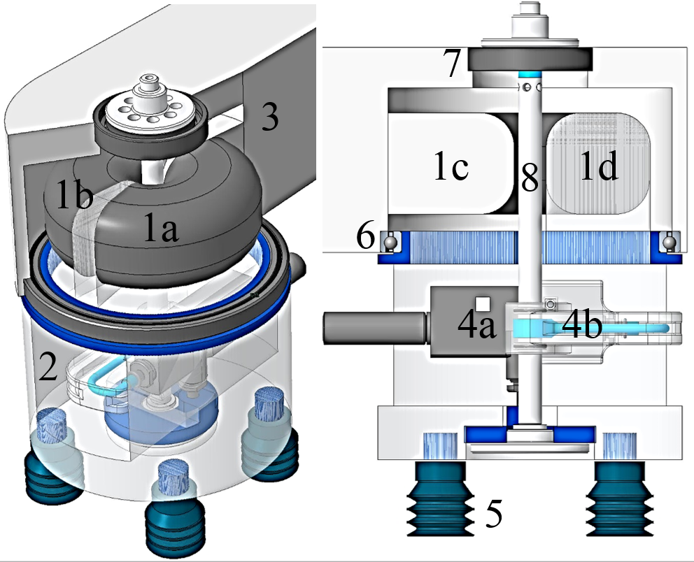 Figure 2: Conceptual design of a PolyJet-printable light-weight gripper with integrated bellows actuator. The main components are the bellows actuator (1), the support structure (2) and a vacuum nozzle (4).
Therefore, compressed air is guided through the hollow shaft (8) into the adapter (4b) and the vacuum nozzle (4a). The hollow shaft (8) is pretensioned against a lower (6) and an upper bearing (7). In order to minimize the contact pressure at the polymeric bearing seats of the attached structural component (3) and keep the weight down, thin section ball bearings (Schaeffler AG, Germany) are chosen. The bottom bearing is a INA CSCA 030 (76,2×88,9×6,35 mm3, Schaeffler AG) and the top bearing is a CSCAA 010 TN (25x37x7 mm3, Schaeffler AG).
2. Bellows Actuators
2.1. Linear Bellows Actuators
The behaviour of linear type bellows actuators is investigated first, as their structural behaviour is simpler to analyse by FEA. Linear bellows actuators were designed (Figure 3), comprised of an elastomeric bellows structure and thermosetting flanges.
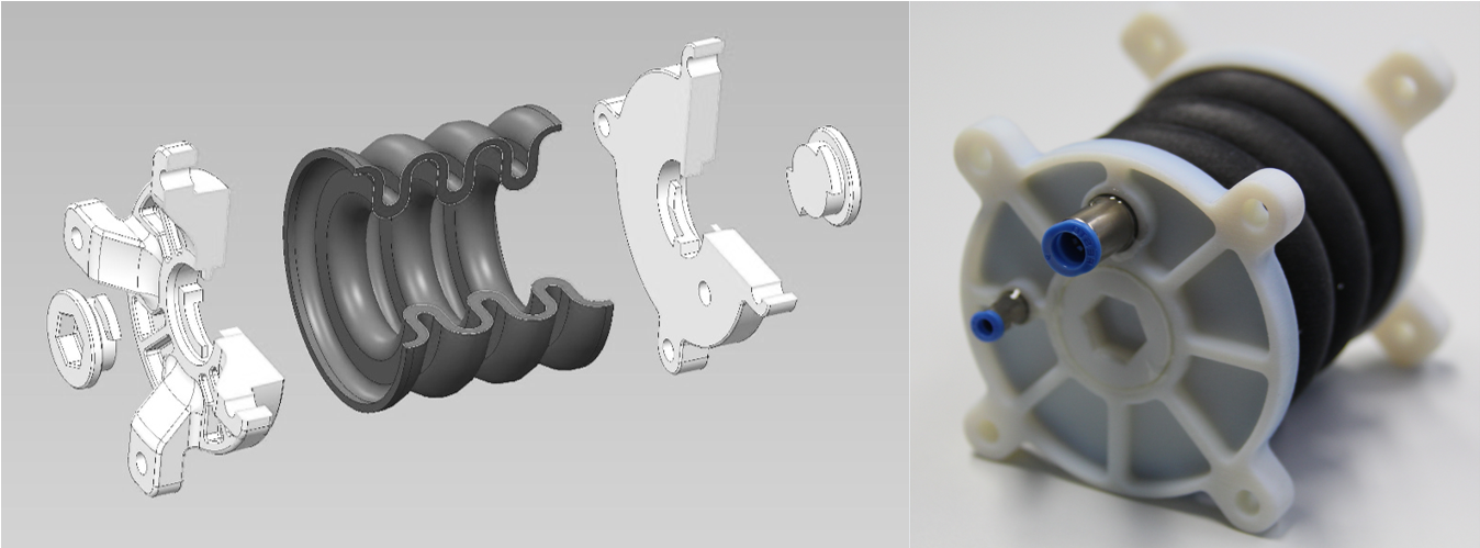 Figure 3: CAD drawing (left) and photograph (right) of a multi-material linear bellows actuator. The bellows structure and flanges are printed in one piece.
The bellows structure and flanges were printed as one monolithic piece and complemented with closing caps and pneumatic connectors (Figure 3). The elastomeric materials TangoBlackPlus™ (TB+) and Agilus30™ (A30) were used. For the flanges VeroWhitePlus™ (VW+) was selected. Actuators with bellows structures made of TB+ were provided by cirp GmbH (Römerstraße 8, 71296 Heimsheim, Germany) and actuators with bellows structures made of A30 by Stratasys® (Haim Holtsman St. 1, 7612401 Rehovot, Israel).
The linear deflection x and “effective force” Feff of a pneumatic actuator depend on multiple factors including the actuator geometry, actuator material and the components of the surrounding pneumatic-mechatronic actuation system. Assuming frictionless guiding and quasi-static conditions, the effective force Feff can be expressed as a function (1) of the pressure force Fp and the structural force Fs that is caused by the bellows deformation.
![]() Thereby, Fp can easily be determined ( ) by multiplying the relative pressure ( = ) and the effective area of the pneumatic chamber. The structural force Fs however, depends on the displacement x and and typically results from an FEA. The curve characteristics of Fs (x, ) depend on the specific bellows geometry and material. Therefore, a geometrical representation and a material model for elastomeric structures of linear bellows actuators are described below.
Thereby, Fp can easily be determined ( ) by multiplying the relative pressure ( = ) and the effective area of the pneumatic chamber. The structural force Fs however, depends on the displacement x and and typically results from an FEA. The curve characteristics of Fs (x, ) depend on the specific bellows geometry and material. Therefore, a geometrical representation and a material model for elastomeric structures of linear bellows actuators are described below.
2.2. Finite Elements Analysis of Linear Bellows
The geometric model is reduced to the bellows structure because the elastic modulus of the flange material is significantly larger than the modulus of the used elastomers (> 1000 MPa [29], compared to 0.5 MPa [30]). In the FEA described below, the flange is represented by boundary conditions applied to the bellows structure’s mesh. For the axisymmetric linear bellows structure (Figure 4), a u-shaped design is chosen that consists of semicircles and parallel lines. The entire bellows structure is defined by 7 design parameters (Figure 4, left). In Figure 4 (right), parameter values (in mm) for an initial (V1) and optimized version (V2) are given and will be referred to in the following.
| Param. | Geom. V1 | Geom. V2 |
| da | 30 | 30 |
| ri | 7.5 | 5.0 |
| ra | 7.5 | 6.5 |
| ta | 32.0 | 32.1 |
| ti | 24.5 | 21.4 |
| di | 24.5 | 20.5 |
| l | 52 | 52 |
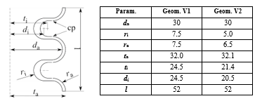 Figure 4: Left: Parameterization of a linear bellows shape with non-constant wall thickness. Control points (cp) are for the evaluation of the distances to adjacent half-waves. Right: Parameter values (Param.) in mm for an initial geometry (Geom. V1) and an optimized geometry (Geom. V2).
The structural force Fs, exerted by the deformed bellows structure, originates in the strive of the molecular chains in the elastomeric material to return to their initial configuration. Typically, a strain energy function U is utilized to describe this entropic elasticity in elastomers on a macroscopic scale [31]. In the polynomial form (2) [32], U is expressed as a function of the first and second invariant ( , ) of the left Cauchy-Green deformation tensor and—in case of compressibility—of the elastic volume strain as
![]() Thereby, and are constants that are related to the deviatoric and volumetric material behavior respectively. Reducing the general polynomial form (2) to the first order (N=1), the Mooney-Rivlin form for compressible materials [32] is obtained as
Thereby, and are constants that are related to the deviatoric and volumetric material behavior respectively. Reducing the general polynomial form (2) to the first order (N=1), the Mooney-Rivlin form for compressible materials [32] is obtained as
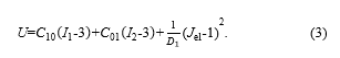 By fitting the Mooney-Rivlin model (3) to uniaxial tensile and compression test data of TB+ with Abaqus’ (Dassault Systèmes) internal fitting procedure, the material constants ( =0.11 MPa, =4.52 MPa, = 2.28 MPa) were determined. A FEA is carried out utilizing the described geometrical and material model. In order to verify the FEA, the effective force Feff for given pressures and deflections x, was measured and compared to simulated results. Figure 5 shows a TB+ bellows actuator mounted to an actuator test bench in three states of enforced displacement. In the testing procedure, the applied pressure difference is controlled by a Festo VPPM pressure control valve (0-2 bar), Feff is measured using a Burster 8523-50 force sensor (+/- 50 N) and the linear displacement x is enforced by a Festo EGSA-50-100 linear axis.
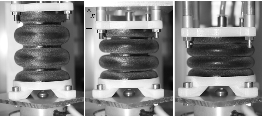 Figure 5: Measuring effective forces Feff of linear bellows actuators for given pressures and enforced displacements. Extension (left), initial (middle) and compression (right) states were tested.
In the experimental procedure, relative pressures were varied in 20 mbar steps from 0 mbar to 140 mbar. Displacements were varied between 20 mm of compression and 30 mm of extension. Noticeably, the effective force was observed to increase for almost 30 s after the enforced displacement states and pressures were reached. Therefore, effective forces at all displacement-pressure combinations were measured after waiting for 30 s. In Figure 6 the experimental and simulated force-pressure-deflection characteristics of a linear bellows actuator are compared. As expected, the effective force Feff exerted by the actuator increases with an increase in relative pressure but generally decreases with an increase in deflection x. For compressions (x < 0), the effective force Feff remains almost constant. Remarkably, none of the interpolated lines covers the full deflection range. Low pressures shift the static force equilibrium (2) and limit the maximum extension. At higher pressures, compression is limited because the waves of the bellows geometry touch adjacent waves (“self-contact”, see Figure 5, right). Results from FEA are generally in good agreement with the experimental results. However, Figure 6 indicates, that deviations correlate with high pressures or elongations i.e. increase with increasing strains. For improved significance of the material model, additional stress states (pure shear, bi-axial) should be considered in the fitting procedure of the constitutive model.
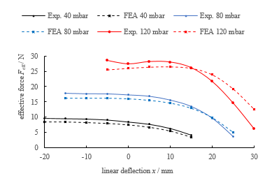 Figure 6: Comparison of the simulated (dashed lines) and experimental results (solid lines) of the effective actuator force Feff as a function of given pressures and forced displacements. Simulations are generally in good accordance with the experiments. Lines are interpolated between measuring points.
2.3. Shape Optimization of Linear Bellows
The underlying concept of a bellows actuator is, that the deformation of a pressurized chamber is utilized to create a linear or rotatory motion. This implies not only the absence of holes in the bounding surface but also leads inevitably to folded structures in which the total actuator displacement is “distributed” into relatively small strains. Consequently, an optimum material lay-out or topology is known a priori (folded structure without holes). Therefore, optimizing a bellows structure can be reduced to the optimization of its shape.
In elastomers that undergo repeated strains [33], [34], material imperfections—also typical for AM materials [28]—cause local strain peaks that can lead to the formation and propagation of microscopic cracks and may eventually result in fatigue failure. In the experiments described above, the bellows structures failed after undergoing repeated deformations i.e. strain. To find an improved bellows design (V2), that reaches similar effective force Feff and deflection x as the initial geometry (V1) but sustains an increased number of load cycles, a numerical optimization routine was developed. Thereby, maximum (logarithmic) principal strain was considered as a fatigue life indicator [35] in the strain objective function
![]() During the optimization process, various designs are created. Sets of design parameters in the design vectors x that lead to simulated strains larger than a reference strain result in large values of the objective function. To achieve a required deflection and avoid self-contact, the specific objective functions for the deflection and self-contact and are stated analogous to . The quality of a design is described by the weighted sum of specific objective functions. The resulting multiple criteria objective function is
During the optimization process, various designs are created. Sets of design parameters in the design vectors x that lead to simulated strains larger than a reference strain result in large values of the objective function. To achieve a required deflection and avoid self-contact, the specific objective functions for the deflection and self-contact and are stated analogous to . The quality of a design is described by the weighted sum of specific objective functions. The resulting multiple criteria objective function is
![]() with , and being weighting factors for the specific objective functions. Therefore, a bellows design is fully described by the design vector
with , and being weighting factors for the specific objective functions. Therefore, a bellows design is fully described by the design vector
![]() Note that has to be variable and is a component of the design vector because the required effective force Feff is implemented as a hard constraint. Additionally, an integer parameter nhw is defined to quantify the (even) number of half-waves that describe the bellows structure. To account for bounds and secondary constraints (their exhaustive description is beyond the scope of this article), a constraint vector is defined. Therefore, the constraint mixed integer bellows optimization problem is
Note that has to be variable and is a component of the design vector because the required effective force Feff is implemented as a hard constraint. Additionally, an integer parameter nhw is defined to quantify the (even) number of half-waves that describe the bellows structure. To account for bounds and secondary constraints (their exhaustive description is beyond the scope of this article), a constraint vector is defined. Therefore, the constraint mixed integer bellows optimization problem is
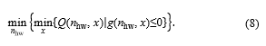 In order to solve the optimization problem (8), an optimization routine was realized that contains the structural simulation and parameterization described above.
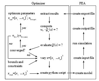 Figure 7: Optimization routine of linear bellows actuators with Matlab (MathWorks) and Abaqus (Dassault Systèmes). The optimization routine finds an optimum bellows shape and corresponding relative pressure concerning a required effective force at defined displacement. Maximum principal strain is minimized in order to increase the fatigue life of the bellows actuator.
Abaqus (Dassault Systèmes) and Matlab (MathWorks) were connected utilizing python scripts as shown in Figure 7. Starting with the initial parameters xstart and the optimization routine terminates with the output of the optimum parameters xopt and opt. The Matlab function fmincon with default settings (gradient based optimizer) was chosen for convenient implementation of bounds and secondary constraints. The optimization routine was run with a maximum strain reference of = 0,2 and a force requirement of 12 N at 30 mm linear deflection. In Figure 8 the max. principal strain distribution of the initial (top left) and the optimized bellows geometry (top right) are displayed. The corresponding shape parameters can be found in Figure 7 (right). The initial geometry (V1) is based on an intuitive design process and comprises four half-waves with constant wall thickness. Applying 140 mbar of relative pressure results in an effective force of 12 N at 30 mm deflection. The corresponding deformation induces a (simulated) maximum principal strain of 65 % that occurs at the inner diameter of the structure (red). The optimized geometry (V2) consists of six half-waves. Wall thickness is non-constant with thickened regions at the inner diameter. Applying 100 mbar at a linear deflection of 30 mm, the effective force is above 12 N. Under these conditions, the (simulated) max. principal strain is 24 % and maximum principal strains are distributed more evenly if compared to the initial geometry (V1) i.e. respective values at the inner and outer diameter are almost equal.
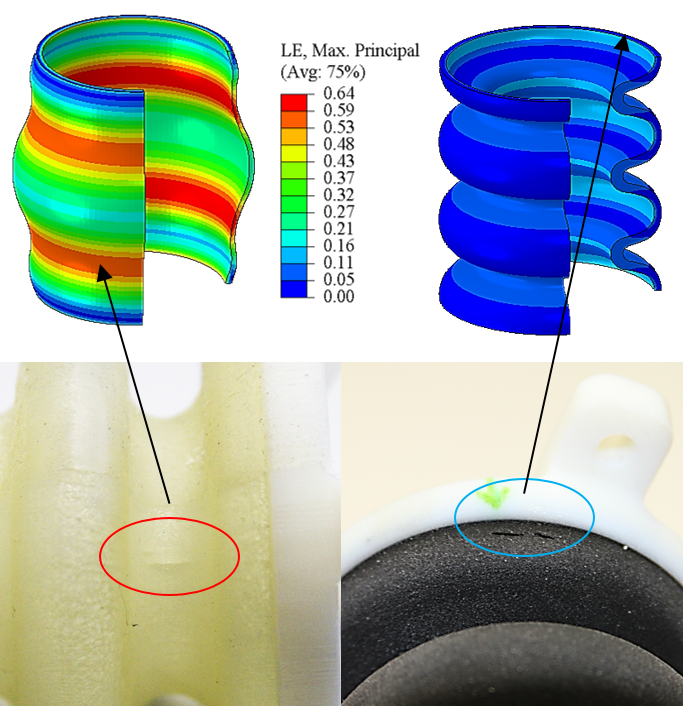 Figure 8: Comparison of the max. principal strain distribution and failures. Cracks in the bellows structure of the initial geometry “V1” (left) are oriented in axial direction occur at the inner diameter. Cracks in the bellows structure of the optimized geometry “V2” (right) are oriented in tangential direction and occur next to the flange. Our observations in the experiments match the locations and are perpendicular to the directions of max. principal strain in the FEA.
Figure 9 shows a comparison of the pressure-force-deflection characteristics of the initial (V1) and optimized (V2) bellows geometry. Noticeably, the effective force of the initial geometry (V1) is significantly more dependent on its deflection. The loss of effective force at increased deflections in Figure 8 is caused by the increased strain in the structure. In the optimized actuator (V2), lower pressures result in similar forces at large displacements. The optimized geometry (V2) satisfies the force constraint of 12 N at 30 mm. Considering the significant reduction of the (simulated) maximum principal strain (from 64 % to 24 %) and fatigue data from literature [28], an increased sustainability of the optimized actuators can be expected.
2.4. Fatigue Testing
In order to examine the hypothesis of an extended fatigue life of the optimized geometry and for comparison of the materials TB+ and A30, endurance runs were performed with the linear bellows actuators. A30 is a recently released PolyJet elastomer with similar hardness range (Shore A 30-35 compared to 26-28 for TB+) as well as a higher elongation at break and tear resistance [36]. Due to superior properties in the data-sheet [36], an increased fatigue life was expected if compared to TB+. The same geometries and material parameters were used for both the TB+ and A30 bellows actuators because no sufficient material data of A30 were available at this time. Therefore, A30 results should be interpreted with care and are presented here for comparison only.
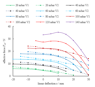 Figure 9: Experimental comparison of the pressure-force-deflection characteristics of the initial (V1, solid lines) and the optimized (V2, dashed lines) bellows geometry. Actuators with the optimized geometry (V2) require significantly less pressure to reach the required forces at 30 mm deflection. Lines are interpolated between measuring points.
In Figure 10, the endurance test bench is displayed. During the test, the right side of the actuator was attached to the test bench (Figure 10). The left side is constrained to horizontal translation by four PTFE-lubricated guiding bolts. The translation was mechanically restrained to 30 mm. In the procedure, a differential pressure of 140 mbar (V1) or 100 mbar (V2) was applied for 30 s. The actuators were vented for another 30 s before the cycle was repeated. Volume flow was measured during the 30 s period to detect possible failure of the bellows structure. The experiment was stopped in case that 2 Nl/min were exceeded.
In Figure 10 the cycles to failure of the tested actuators are displayed. Thereby, cycles to failure range from below 20 (TB+, V1) to more than 30000 (A30, V2). A30 bellows with the initial geometry (V1) endured 143 load cycles in average. With the optimized geometry (V2), A30 bellows endured an average of 24104 load cycles. Despite the relatively small number of specimen (each point in Figure 10 corresponds to a single endurance run), our results indicate that the optimized geometry (V2) sustains significantly more cycles until failure if compared to the initial geometry (V1). Moreover, we conclude that bellows made from A30 can endure more cycles to failure compared to those manufactured from TB+. Noticeably, different geometries lead to two consistent categories (i.e. modes and locations) of failures. As shown in Figure 8 (bottom), all specimens of the initial geometry (V1) show axial cracks at the inner diameter of the structure (Figure 8, bottom left). In the corresponding FEA, maximum principal strains are oriented perpendicular to the observed cracks and located at the inner diameter. Actuators with the optimized shape (V2) consistently show tangential cracks (i.e. perpendicular to axial strains) near the flanges as shown in Figure 8 (bottom right). To reduce strains at the flange region of the optimized shape (V2) additional shape parameters could be introduced in the optimization routine.
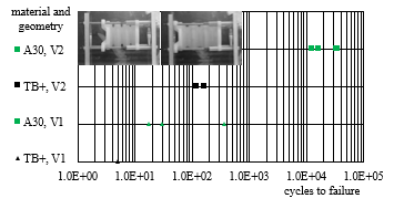 Figure 10: Endurance run with linear bellows actuators load cycles to failure of PolyJet printed linear type bellows actuators. Cycles of pressurization (extension) and ventilation (contraction) were performed until a threshold volume flow was exceeded as an indicator of structural failure. Most cycles to failure were obtained from the combination of Agilus30 (A30) with an optimized bellows shape (V2).
2.5. Rotary Bellows Actuators
The investigations described above pose an intermediate step in the development process of a PolyJet light-weight gripper with integrated elastomeric bellows actuators (number (2) in Figure 8). Three main findings can be formulated as a basis for the initial design of a rotary type bellows actuator.
- A constant wall thickness leads to extensive strains at the inner diameter of the bellows structure. Thickening this area (as proposed by the shape optimization algorithm), may lead to an increased number of sustainable cycles.
- A30 should be used instead of TB+ as we observed significantly increased fatigue life for the same geometries and loading conditions.
- In the performed endurance runs, modes and locations of failure largely corresponded with maximum principal strain in our FEA. Reducing this value to 20 – 25 % delivered acceptable sustainability.
As already displayed in the conceptual gripper model (Figure 2) one rotary actuator comprises two antagonistic (i.e. separate) chambers (1a, 1b). Following this concept and based on the findings of the previous section, an initial geometry was defined in Creo (PTC Inc.) and imported into Abaqus CAE (Dassault Systèmes) for structural analysis and refinement of the bellows shape. The final design of a single chamber for the rotary bellows actuator is displayed in Figure 11. In contrast to existing designs, buckling of the deformable structure is prevented by a roller guiding system and radial forces are supported by the surrounding structure.
As displayed in Figure 12 (top), each chamber is built up from four equal elastomeric segments (1). Between the elastomeric sections, rigid frames (2) are placed that hold rotatable rollers (3). The fixed flange can be attached to the robot link and the movable flange (5) to the gripper’s support structure which is pivoted as shown in Figure 2. Under extension or compression, each segment (within one chamber) undergoes the same deformation.
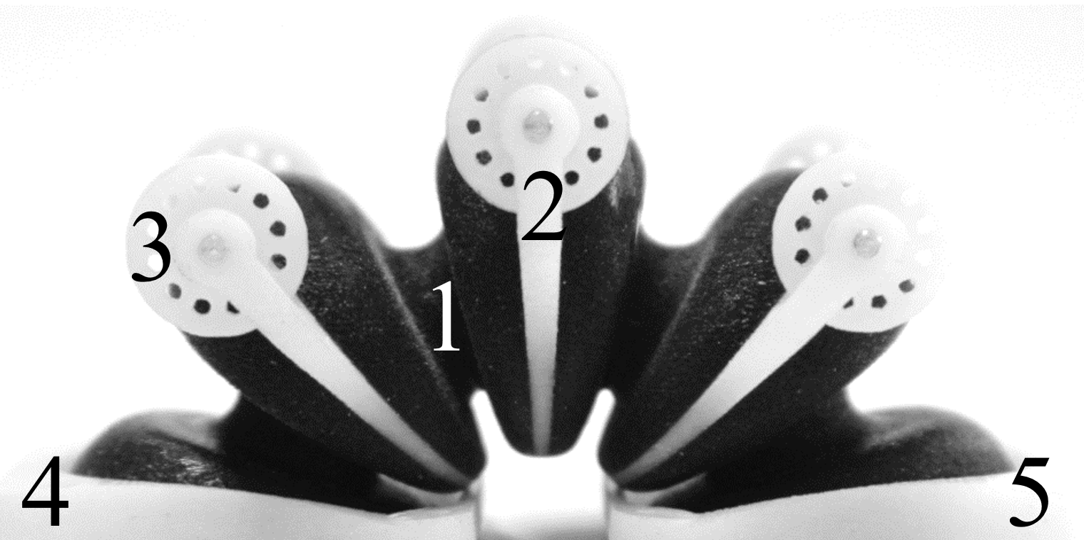 Figure 11: Single chamber for a rotary type bellows actuator. The main components are the soft bellows segments (1), frames (2), rollers (3) and flanges (4,5). The rollers prevent buckling of the bellows structure. The frame-roller combination at the end of each bellows segment subdivide the design into equal design features which facilitates structural analysis and scalability.
As displayed in Figure 12 (top), each chamber is built up from four equal elastomeric segments (1). Between the elastomeric sections, rigid frames (2) are placed that hold rotatable rollers (3). The fixed flange can be attached to the robot link and the movable flange (5) to the gripper’s support structure which is pivoted as shown in Figure 2. Under extension or compression, each segment (within one chamber) undergoes the same deformation.
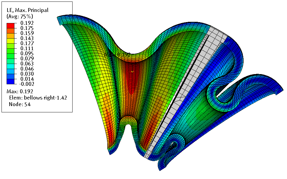 Figure 12: In the printed actuator (top), four identical segments are arranged in series to one of two counteracting chambers. In the corresponding FEA (bottom), two segments are considered because the expansion of one chamber denotes the compression of the antagonistic chamber.
This is due to the serial arrangement within a chamber and the roller guiding system that inhibits buckling. However, the expansion of one chamber denotes the compression of the antagonistic chamber. In the corresponding FE model, the roller guiding system was modelled by constraining the motion of the frame to the rotational degree of freedom (DOF) about the center axis. Hence, the FE model (Figure 12, bottom) was reduced to one half of a bellows segment of one agonist and one antagonist chamber. Nodes at the left and right side are constrained in all DOF. The geometry was meshed so that the bellows structures thickness was represented by 6 (quadratic) elements. For the bellows structure, the hyper-elastic Mooney-Rivlin material model was used as described in paragraph 3 whereas the frame was modelled as a rigid body. A linearly increasing pressure load was applied to the inner surface of the left bellows segment and left surface of the flange. The analysis type was set to non-linear quasi-static. The occurring (logarithmic, maximum principle) strains were interpreted as a fatigue life indicator. The geometry was then optimized by iteratively adding material at locations of extensive strain and removing material from less strained sections. The final geometry was defined after 5 iterations of re-design in Creo (PTC Inc.) and re-analysis in Abaqus (Dassault Systèmes) and provides a good compromise between the estimated max. rotation angle (95°) at 90 mbar and estimated max. principal strain (19 %). The described FEA does not consider any inertial loads or friction in the roller guiding system and bearings (Figure 2). Therefore, the simulated angular deflection should be interpreted as an upper limit. In initial measurements, a maximum deflection of 50-60° at 90 mbar was observed. The described actuator reaches a theoretical maximum torque of 86 Nmm at 90 mbar and 0° deflections. Apparently, overcoming the frictional torque of the rollers and bearings requires already a considerable fraction of the theoretical torque.
3. Light-Weight Structure
3.1. Density Based Topology Optimization
For the optimization of the bellows shape, a boundary variation approach was applied that is based on an a priori known optimum (or at least very reasonable) material lay-out. However, concerning the light-weight structure of the gripper, no reasonable initial shape can be defined based on intuition or examples. This is due to the complexity of the design space and expected loads and because discontinuities (“holes”) in the structure are permissible. The general task for the design of the gripper’s support structure is to determine the optimum spatial material distribution within the design space (as shown in Figure 2) that results in a maximum stiffness considering typical or critical loads and boundary conditions. This is exactly what is known today under the term “topology optimization” (TO). In the following, some of the fundamental concepts and equations for density-based minimum (weighted) compliance TO are explained. Detailed descriptions and exemplary Matlab code of density-based TO can be found in [6] and [37].
In typical TO approaches, the objective (and constraint) functions are structural responses from a corresponding FEA. Therefore, an FE model is set up with the discretized geometry being subdivided into design- and non-design regions. The task of the optimizer is to decide for each element of the design region if it should be void or material. As this is clearly an integer problem [8] and the optimization of a large number of discrete variables is computationally time-consuming [38], in popular algorithms ([8], [38]), continuous pseudo densities are introduced for each element. Moreover, the stiffness of each element is coupled to its pseudo density that can continuously be varied (9) between 0 (void) and 1 (solid material) by the optimizer. Hence, the design variables of (density based) topology optimization are the continuous pseudo element densities coupled to the elements in the design space.
![]() However, intermediate densities i.e. values for that are not 0 or 1, can generally not be translated into fractions of real-world structures. In the so-called “power-law” or “SIMP” (Solid Isotropic Material with Penalization) approach the stiffness of each element is coupled to its pseudo density in a nonlinear manner (10). is the pseudo or penalized stiffness matrix of an element, is the elements pseudo density to the power of a penalization factor p (p > 1) and is the initial/non-penalized stiffness matrix of an element.
However, intermediate densities i.e. values for that are not 0 or 1, can generally not be translated into fractions of real-world structures. In the so-called “power-law” or “SIMP” (Solid Isotropic Material with Penalization) approach the stiffness of each element is coupled to its pseudo density in a nonlinear manner (10). is the pseudo or penalized stiffness matrix of an element, is the elements pseudo density to the power of a penalization factor p (p > 1) and is the initial/non-penalized stiffness matrix of an element.
![]() By choosing p > 1, intermediate densities become “uneconomical” [6] because the cost (volume or mass) of an element is high, compared to its penalized stiffness. If the individual element stiffness matrices are assembled to a global stiffness matrix of the structure, the compliance can be defined as a reciprocal measure of the structures stiffness as
By choosing p > 1, intermediate densities become “uneconomical” [6] because the cost (volume or mass) of an element is high, compared to its penalized stiffness. If the individual element stiffness matrices are assembled to a global stiffness matrix of the structure, the compliance can be defined as a reciprocal measure of the structures stiffness as
![]() In (11), u is the displacement vector. In order to rate the compliance of a structure subjected to multiple load cases i in a single scalar value, the sum of the compliances , of each individual load case is built using weighting factors as shown in (12).
In (11), u is the displacement vector. In order to rate the compliance of a structure subjected to multiple load cases i in a single scalar value, the sum of the compliances , of each individual load case is built using weighting factors as shown in (12).
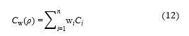 The minimum weighted compliance optimization problem can now be formulated as
 with (14) expressing the equilibrium of external (f) and internal forces for a static load case that has to be satisfied for each FEA iteration and (15) defining the value range for the design variables . The volume fraction v constrains the amount of used volume in the design space in relation to the initial volume of the design space (16).
3.2. Optimization of Support Structure
For the TO of the gripper’s light-weight structure, HyperWorks software was used (Altair Engineering Inc.) with HyperMesh, OptiStruct and HyperView for pre-processing, solving FEA iterations/optimization and post-processing the results respectively. In OptiStruct, the above described SIMP method was implemented [38]. As the objective function value is computed from the structural responses of an FEA, a suitable FE model was set up first. For an initial analysis, the conceptual geometry (as displayed in Figure 2) was reduced to one fourth and imported to Hypermesh (Figure 13). The geometry was discretized with 43096 CTETRA elements from which 38354 belong to the design space (transparent) and 4742 to the non-design space (blue). As strains were expected to be small and contacts were modelled with rigid body elements, a linear static analysis was set up (this also corresponds to the described approach in section 3.1). Uni-axial tensile testing of VW+ specimen revealed that for small strains the material behavior can be assumed to be linear and isotropic with an elastic modulus of 1809.00 MPa and a Poisson’s ratio of 0.42.
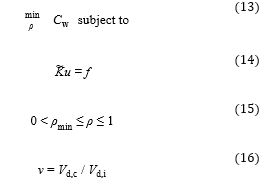
 Figure 13: FEA of a light-weight gripper. One fourth of the gripper is modelled including the design space (transparent) and the non-design space (blue).
As shown in Figure 13 loads were applied for pretension of the bearing (force 1: 50.0 N), lifting the payload (force 4: 17.0 N) as well as centrifugal forces resulting from the rotational motion of the whole robot (forces 2 and 3: 35.4 N each). Loads were applied to the independent nodes of 1D RBE2 elements (black). The dependent nodes of the RBE2 elements were attached to the respective nodes in the non-design space with all DOF constrained. It must be pointed out, that the definition of two symmetry planes was made to reduce time in the development (computational time and time for design interpretation). The two planes of symmetry are valid for the load cases “pretension” and “lift” but not for the loads resulting from the rotation of the robotic arm. However, loads in radial direction were considered to drive the design towards a structure that is less sensitive to actual dynamic loads in operation. A TO was performed based on the above described FE model and according to the problem definition ((13)-(16)). The volume fraction was set to v=0.15 (16) and the four loads were weighted equally in the weighted compliance calculation (12). was set to 0.01 (default). OptiStruct uses gradient-based optimization algorithms [38] in which the sensitivity of the response ( ) is calculated with respect to the design variables . In this case, convergence was reached within 29 iterations. In Figure 14 (top left) the optimization result is shown. For the illustration, the obtained geometry is mirrored by the (assumed) planes of symmetry. Noticeably, the main feature of the structure is a straight connection from the base-plate at the bottom to the bearing seat at the top. Smaller Features are the connections from the attachment points of the suction cups to the base plate and bearing seat. This result seems meaningful because the dominant load (load 1 in Figure 13) results in a compression of the structure between the base plate and the bearing seat. The features connecting the attachment points of the suction cups to the rest of the structure are generally in accordance with the directions of applied loads (loads 2 and 3: radial; load 4: vertical).
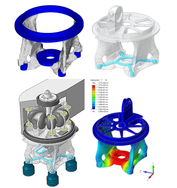 Figure 14: Optimization results and final design. Results of topology optimization (top left) were interpreted with Altair Inspire PolyNurbs (top right). Details were added to achieve the final design (bottom left) and the final structure was re-analyzed (bottom right).
The structure was remodeled using PolyNurbs functionality of Altair Inspire. Moreover, the geometry was re-imported to Creo (PTC Inc.) and features such as threads for the suction cups, internal air guidings (blue colored in Figure 14, top right) and an attachment for the bellows actuator were added. A CAD drawing of the gripper assembly is displayed in Figure 14 (bottom left). A re-analysis was performed (Figure 14, bottom right) and the structure was inspected for strain peaks. When interpreting the results, it must be mentioned, that the elastic modulus of VW+ is significantly rate-dependent which is typical for polymers. The choice of modulus might be considered less important when performing a minimum compliance TO, based on linear static load cases. However, rate-dependency of the modulus in combination with a mixture of long-term static (preload and lift and hold) and dynamic loads (rotatory motion of the robot) bring a certain vagueness to the computation of the weighted compliance (eq. 12) and re-analysis. In further research, the effect of rate-dependent material behavior on the optimization result should be considered.
4. Final Design and Application in Light-Weight Robot
Multiple Grippers were printed by Stratasys ® (Haim Holtsman St. 1, 7612401 Rehovot, Israel) and cirp (cirp GmbH Römerstraße 8, 71296 Heimsheim, Germany). In Figure 15 a prototype of the developed gripper is displayed. Including bottom and top bearing as well as the adapter with vacuum nozzle, the gripper has a weight of 263 g (Figure 15, left) of which the printed multi-material structure constitutes 102 g.
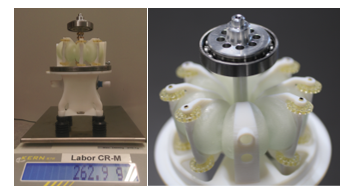 Figure 15: Prototype of a multi-material light-weight gripper with integrated elastomeric bellows actuator. Left: the printed light-weight structure and bellows contribute less than half of the total weight. Right: top-end of the gripper with roller guiding system.
A gripper was mounted to the PolyJet printed light-weight robot that was developed for the DIMAP project (Figure 16). The functioning robot was presented to the public at the formnext2018 faire (19.-22.11.2019, Frankfurt, Germany) at the cirp booth (cirp GmbH Römerstraße 8, 71296 Heimsheim, Germany).
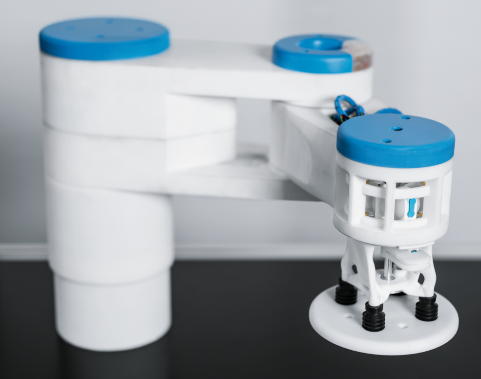 Figure 16: Light-weight gripper attached to the DIMAP SCARA (© Festo).
During the four days, no failure occurred and all the features (bellows actuator, vacuum system, light-weight structure) worked flawlessly. Figure 15 shows the PolyJet printed light-weight robot “DIMAP SCARA” with the attached gripper in a typical pick and place application. Objects of more than 1 kg can be lifted with the described configuration of vacuum nozzle and suction cups.
5. Conclusion
Additively manufactured bellows actuators pose an interesting option for the actuation of future robotic systems as their structural behavior is highly tunable by variations of shape and material. By using state-of-the-art AM technologies such as multi-material PolyJet™ printing, soft actuators can be integrated into stiff and light-weight support structures resulting in highly integrated and geometrically complex components. Though there are many publications that contain AM bellows actuators or suitable light-weight design approaches, the combination of both has hardly been investigated so far. In this article, the simulation-driven design process of a multi-material light-weight vacuum gripper with an integrated bellows actuator is described with the aim to demonstrate possible development approaches and the application in a printed light-weight robot. Based on a conceptual gripper design, investigations were separated into the actuator and support structure development. To understand the structural and fatigue behavior of elastomeric PolyJet bellows, linear type multi-material bellows actuators were designed using VeroWhitePlus™ (VW+) material for the rigid flanges and TangoBlackPlus™ (TB+) for the soft bellows structure. Starting from very few (below 50) sustainable load cycles, optimizing the bellows shape and using Agilus30™ (A30) instead of TB+ material, increased the fatigue life to more than 20.000. Based on these findings, a rotary type actuator was designed that consists of two antagonistic chambers with each chamber being a linear arrangement of equal bellows segments. If compared to existing solutions, the design of the novel guiding system facilitates structural analysis and scalability of the geometry. In order to develop the gripper’s support structure, the fundamentals of density-based minimum (weighted) compliance topology optimization were developed and applied to the conceptual gripper design. Considering multiple load cases, an optimum material lay-out was defined. By merging the rotary bellows actuator and the light-weight structure, a fully functional multi-material vacuum gripper was obtained that reaches rotatory deflections of more than 60°, can lift and hold objects of more than 1 kg and has a weight of 263 g of which the printed multi-material structure constitutes 102 g. Finally, the gripper was mounted to a PolyJet printed light-weight robot and its functionality was successfully presented to the public at the formnext2018 faire in Frankfurt, Germany. The described development steps and design solutions can be transferred to other manufacturing technologies.
Conflict of Interest
The authors declare no conflict of interest.
Acknowledgment
The authors of this paper thank for the opportunity to be involved in the DIMAP project funded as part of the Horizon 2020 Framework program for research and innovation under the grant agreement no 685937. Moreover, we thank the responsible persons for the organization of the 2018 IEEE international conference on Soft Robotics (RoboSoft) and publication of the conference paper [1]. The software used for the simulation-driven design of the light-weight structure was kindly provided by Altair Engineering Inc..
- G. Dämmer, S. Gablenz, A. Hildebrandt, and Z. Major “Design and Shape Optimization of PolyJet Bellows Actuators,” in Proc. 2018 IEEE International Conference on Soft Robotics (RoboSoft), 2018. https://doi.org/10.1109/ROBOSOFT.2018.8404933
- A. Clausen, N. Aage, and O. Sigmund “Exploiting Additive Manufacturing Infill in Topology Optimization for Improved Buckling Load”. Engineering, vol. 2, no. 2, pp. 250-257, 2016. https://doi.org/10.1016/J.ENG.2016.02.006
- A. M. Mirzendehdel and K. Suresh “A Pareto-optimal approach to multimaterial topology optimization”. Journal of Mechanical Design, vol. 137, no. 10, pp. 101701-12, 2015. https://doi.org/10.1115/1.4031088
- DIN ISO/TS 15066:2017-04 “Robots and robotic devices – Collaborative robots,” 2017.
- M. Zinn, B. Roth, O. Khatib, and J. K. Salisbury “A new actuation approach for human friendly robot design”. The international journal of robotics research, vol. 23, no. 4-5, pp. 379—398, 2004. https://doi.org/10.1177/0278364904042193
- M. P. Bendsøe and O. Sigmund, Topology optimization: theory, methods, and applications. Springer Science+Business Media, 2013, ISBN 978-3-662-05086-6. https://doi.org/10.1007/978-3-662-05086-6
- R. V. Kohn and G. Strang “Optimal design and relaxation of variational problems, I”. Communications on pure and applied mathematics, vol. 39, no. 1, pp. 113-137, 1986. https://doi.org/10.1002/cpa.3160390107
- M. P. Bendsøe “Optimal Shape Design as a material distribution Problem”. Structural and Multidisciplinary Optimization, vol. 1, no. 4, pp. 193-202, 1989. https://doi.org/10.1007/BF01650949
- J. Liu, A. T. Gaynor, S. Chen, Z. Kang, K. Suresh, A. Takezawa, L. Li, J. Kato, J. Tang, W. Jinyuan et al. “Current and future trends in topology optimization for additive manufacturing”. Structural and Multidisciplinary Optimization, vol. 57, no. 6, pp. 2457-2483, 2018. https://doi.org/10.1007/s00158-018-1994-3
- J. Liu, and Y. Ma “A survey of manufacturing oriented topology optimization methods”. Advances in Engineering Software, vol. 100, pp. 161-175, 2016. https://doi.org/10.1016/j.advengsoft.2016.07.017
- T. Zegard and G. H. Paulino “Bridging topology optimization and additive manufacturing”. Structural and Multidisciplinary Optimization, vol. 53, no. 1, pp. 175-192, 2016. https://doi.org/doi:10.1007/s00158-015-1274-4
- A. T. Gaynor, N. A. Meisel, C. B. Williams, and J. K. Guest “Multiple-material topology optimization of compliant mechanisms created via PolyJet three-dimensional printing”, Journal of Manufacturing Science and Engineering, vol. 136, no. 6, pp. 0610151-10, 2014. https://doi.org/10.1115/1.4028439
- S. Junk, B. Klerch, L. Nasdala, and U. Hochberg “Topology optimization for additive manufacturing using a component of a humanoid robot,” in Proc. 28th CIRP Design Conference, pp. 102-107, 2018. https://doi.org/10.1016/j.procir.2018.03.270
- P. W. Christensen and A. Klarbring, An Introduction to Structural Optimization. Springer Science+Business Media, 2008, ISBN 978-1-4020-8666-3.
- T. Lens, J. Kunz, O. Von Stryk, C. Trommer, and A. Karguth “Biorob-arm: A quickly deployable and intrinsically safe, light-weight robot arm for service robotics applications,” in Proc. 41st International Symposium on Robotics (ISR) and 6th German Conference on Robotics (ROBOTIK), pp. 905-910, 2010.
- M. Grebenstein, A. Albu-Schäffer, T. Bahls, M. Chalon, O. Eiberger, W. Friedl, R. Gruber, S. Haddadin, U. Hagn, R. Haslinger et al. “The DLR hand arm system,” in Proc. 2011 IEEE International Conference on Robotics and Automation (ICRA), pp. 3175-3182, 2011. https://doi.org/10.1109/ICRA.2011.5980371
- B. Vanderborght, A. Albu-Schäffer, A. Antonio, E. Burdet, D. G. Caldwell, R. Carloni, M. Catalano, O. Eiberger, W. Friedl, G. Ganesh et al. “Variable impedance actuators: A review”. Robotics and autonomous systems, vol. 61, no. 12, pp. 1601—1614, 2013. https://doi.org/doi:10.1016/j.robot.2013.06.009
- A. J. Veale and S. Q. Xie “Towards compliant and wearable robotic orthoses: A review of current and emerging actuator technologies”. Medical engineering & physics, vol. 38, no. 4, pp. 317-325, 2016. https://doi.org/doi:10.1016/j.medengphy.2016.01.010
- D. Baiden and O. Ivlev “Independent torque and stiffness adjustment of a pneumatic direct rotary soft-actuator for adaptable human-robot-interaction,” in Proc. 23rd International Conference on Robotics in Alpe-Adria-Danube Region (RAAD), September 2014. https://doi.org/10.1109/RAAD.2014.7002257
- R. MacCurdy, R. Katzschmann, K. Youbin, and D. Rus “Printable Hydraulics: A Method for Fabricating Robots by 3D Co-Printing Solids and Liquids,” in Proc. 2016 IEEE International Conference on Robotics and Automation (ICRA), 2016. https://doi.org/10.1109/ICRA.2016.7487576
- A. Grzesiak, R. Becker, and A. Verl “The bionic handling assistant: a success story of additive manufacturing”. Assembly Automation, vol. 31, no. 4, pp. 329—333, 2011. http://dx.doi.org/10.1108/01445151111172907
- D. Drotman, S. Jadhav, M. Karimi, M. T. Tolley et al. “3D printed soft actuators for a legged robot capable of navigating unstructured terrain,” in Proc. 2017 IEEE International Conference on Robotics and Automation, ICRA, pp. 5532-5538, 2017. http://dx.doi.org/10.1109/ICRA.2017.7989652
- B. N. Peele, T. J. Wallin, H. Zhao, R. F. Shepherd “3D printing antagonistic systems of artificial muscle using projection stereolithography”. Bioinspiration & Biomimetics, vol. 10, no. 5, 2015. http://dx.doi.org/10.1088/1748-3190/10/5/055003
- B. Mosadegh, P. Polygerinos, C. Keplinger, S. Wennstedt, R. F. Shepherd, U. Gupta, J. Shim, K. Bertoldi, C. J. Walsh, G. M. Whitesides “Pneumatic networks for soft robotics that actuate rapidly”. Advanced Functional Materials, vol. 24, no. 15, pp. 2163-2170, 2014. http://dx.doi.org/10.1002/adfm.201303288
- I. Gaiser, A. Andres, G. Bretthauer, H. Breitwieser, O. Ivlev, R. Wiegand, S. Schulz “Compliant robotics and automation with flexible fluidic actuators and inflatable structures,” INTECH Open Access Publisher, 2012. http://dx.doi.org/10.5772/51866
- A. Zolfagharian, A. Z. Kouzani, S. Y. Khoo, A. A. A. Moghadam, I. Gibson, A. Kaynak “Evolution of 3D printed soft actuators”. Sensors and Actuators, vol. 250, pp. 258-272, 2016. https://doi.org/10.1016/j.sna.2016.09.028
- P. Polygerinos, N. Correll, S. A. Morin, B. Mosadegh, C.D. Onal, K. Petersen, M. Cianchetti, M. T. Tolley, R. F. Shepherd “Soft Robotics: Review of Fluid-Driven Intrinsically Soft Devices; Manufacturing, Sensing, Control, and Applications in Human-Robot Interaction”. Advanced Engineering Materials, 2017. http://dx.doi.org/10.1002/adem.201700016
- J. P. Moore and C. B. Williams “Fatigue properties of parts printed by PolyJet material jetting”. Rapid Prototyping Journal, vol. 21, no. 6, pp. 675-685, 2015. http://dx.doi.org/10.1108/RPJ-03-2014-0031
- O. Sheikhnejad, F. Hiptmair, and Z. Major “Finite element simulation and mechanical modelling of nanoparticles reinforced composite,” in Proc. 6th International Conference on Additive Technologies, 2016.
- M. Reiter and Z. Major “A combined experimental and simulation approach for modelling the mechanical behaviour of heterogeneous materials using rapid prototyped microcells”. Virtual and Physical Prototyping, vol. 6, no. 2, pp. 111-120, 2011. http://dx.doi.org/10.1080/17452759.2011.586949
- R. W. Ogden, Non-linear elastic deformations. Dover Publications, Inc., Mineola, 1997, ISBN: 9780486696485.
- Dassault Systemes Simulia Corp “Abaqus Theory Guide. Version 6.14,”, 2014.
- A.N. Gent, P.B. Lindley, and A.G. Thomas “Cut growth and fatigue of rubbers. I. The relationship between cut growth and fatigue”. Journal of Applied Polymer Science, vol. 8, no. 1, pp. 455-466, 1964. https://doi.org/10.1002/app.1964.070080129
- G.J. Lake and P.B. Lindley “Cut growth and fatigue of rubbers. II. Experiments on a noncrystallizing rubber”. Journal of Applied Polymer Science, vol. 8, no. 2, pp. 707-721, 1964. https://doi.org/10.1002/app.1964.070080212
- Y. Zhou, “Fatigue Properties Of Magnetorheological Elastomers And The Design Of Interfacial Layers To Improve Fatigue Life.” Ph.D. thesis, Dublin Institute of Technology, Ireland, 2016. https://doi.org/doi:10.21427/D75315
- Stratasys Ltd, “PolyJet Materials DataSheet”, [Online]. Available: http://usglobalimages.stratasys.com/Main/Files/Material_Spec_Sheets/MSS_PJ_PJMaterialsDataSheet.pdf?v=635785205440671440. [Accessed: Feb. 26. 2018].
- O. Sigmund “A 99 line topology optimization code written in Matlab”. Structural and Multidisciplinary Optimization, vol. 21, no. 2, pp. 120-127, 2001. https://doi.org/10.1007/s001580050176
- OptiStruct, Altair “OptiStruct 11.0 user manual”, Altair Engineering Inc, Troy, MI Google Scholar, 2011.