Novel CPW-fed UWB antenna for X-band applications

Adv. Sci. Technol. Eng. Syst. J. 4(2), 78–82 (2019);
 DOI: 10.25046/aj040210
An ultra-wideband (UWB) printed antenna (PMA) powered by a compact coplanar waveguide (CPW) is featured. The propounded antenna is supposed to cover the UWB range from 7 GHz to 10 GHz, with return loss values below -10 dB in the whole frequency range, for X-band applications, often used for dense satellite communications. The 30 x 35 x 1.6 mm3 antenna is mounted on a dielectric substrate named FR-4 with thickness h=1.6mm, relative permittivity εr=4.3 and loss tangent of 0.025. All the conception and simulated results are realized using the 3D Electromagnetic Simulator software CST Microwave Studio. The results show wide bandwidth and good omnidirectional radiation patterns in the operating band, with a very reduced size. The global satisfying achievement with a very simple structure and small size makes the propounded antenna attractive for use in ultra-wide band (UWB) systems, especially for X-band applications.
1. Introduction
In recent years, there have been new and different mobile standards established in the context of the explosive growth in wireless services that require both higher communication data rate and larger bandwidth. Ultra-Wide Band (UWB) antennas have shown a renewed interest since the allocation by the Federal Communication Commission (FCC) of the bandwidth from 3.1 to10.6 GHz in 2002 [1-2]. This allocation has excited antenna designers to seek for challenging designs of low-cost UWB antennas.
Ultra-wideband technology is potentially the most adequate technologies for future wireless communication system due to various satisfying factures such as ultra-wide bandwidth, low power consumption, high data rate transmission and admirable immunity to multi-patch interference.
A variety of antenna’s models have been explored for UWB applications [3-5]. Nevertheless, the operating band of UWB communication systems includes other frequency bands. Therefore, UWB communication systems may generate interference with those bands. To overcome problems caused by electromagnetic interference (EMI) from UWB to other applications, a new antenna for X-band applications is introduced to avoid possible interferences with existing communication systems running over the whole range of UWB. Different methods for generating CP waves were investigated [6-7]. Coplanar waveguide (CPW) feed antennas with slots are broadly used in many applications because of their advantageous qualities like one metallic layer, simple integration and low profile and wide impedance bandwidth
The propounded antenna is designed utilizing slots of many forms in the radiating patch.
In this paper, a CPW-fed UWB antenna design method is presented, using U shape slot. The operating mechanism and design methodology of the antenna are investigated. The remaining of this paper organized as follows. Section 2 presents the configuration and the parametric study of our antenna. Simulation results accompanied with some discussions are presented in the third Section. In the end, Section 4 summarizes the paper.
2. Antenna Design and Configuration
Normally, the bandwidth of a micro-strip antennas is not very broad, they have narrow bandwidth. Therefore, to conceive an UWB antenna, the conventional technique consist on cutting slots of various forms in the radiating patch is required. The structure of the antenna is depicted in Figure 1. To improve the bandwidth of the propounded antenna, the radiating element is modified by cutting U-shaped slots on its middle [8-10]. Many methods have been already employed in the design in order to obtain wideband antennas by using Different slot shapes that are available and explored by various researchers [11-13]. Among rectangular slot, T-H-L shaped slots and many others, U-slot antennas have proven to be advantageous in that context [14-16]. Although, placement and design of the slots is more challenging than the other methods.
The antenna includes a rectangular patch which is fed by a common coplanar waveguide (CPW) transmission line, mounted on the dielectric substrate FR4-lossy, with thickness h=1.6 mm, relative permittivity εr=4.3 and loss tangent of 0.025, having dimensions of 30 x 35 x 1.6 mm3.
The choice of CPW is due to its easy unification with slots and also to its uniplanar and conformal shape. To ensure a 50-Ω characteristic impedance, the width of the CPW feeder line is fixed at 3.6 mm. A transmission line with characteristic impedance Z0 can simply represent CPW in the equivalent circuit model. Closed-form expressions are given in [17] For the effective dielectric constant and characteristic impedance of CPW. The small gap between the radiating element and the ground plane is the main reason in the excessive capacitive coupling. The manufacturing of the antenna is very simple and inexpensive as both the radiating element and the ground plane are implemented on the same plane, only a single-sided metallization substrate with one layer is utilized [18].
The antenna’s features have been optimized through CST Microwave Studio with Time-domain solver, a market-oriented electromagnetic simulator relying on finite integration technique. The optimized antenna’s parameters of the are listed in Table 1 and the flow chart presenting the design methodology of the CPW-fed ultra-wideband antenna is depicted in Figure 2.
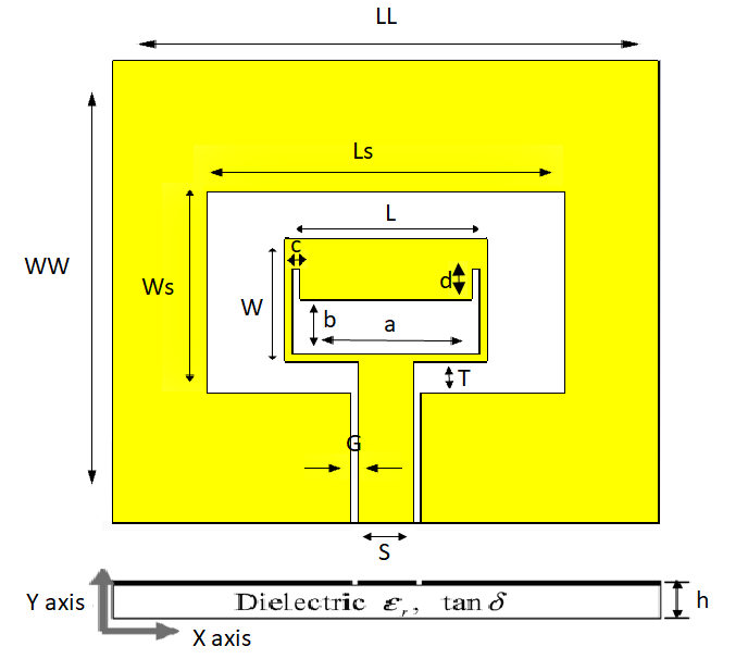 Figure 1 Propounded UWB antenna’s structure
Table 1 parameter values of the propounded antenna
| Parameters | Values (mm) |
| LL | 35 |
| WW | 30 |
| Ls | 23 |
| Ws | 13 |
| L | 13 |
| W | 8 |
| T | 2 |
| G | 0.5 |
| S | 3.6 |
| h | 1.6 |
| Mt | 0.07 |
| a | 12 |
| b | 3.5 |
| c | 0.5 |
| d | 2 |
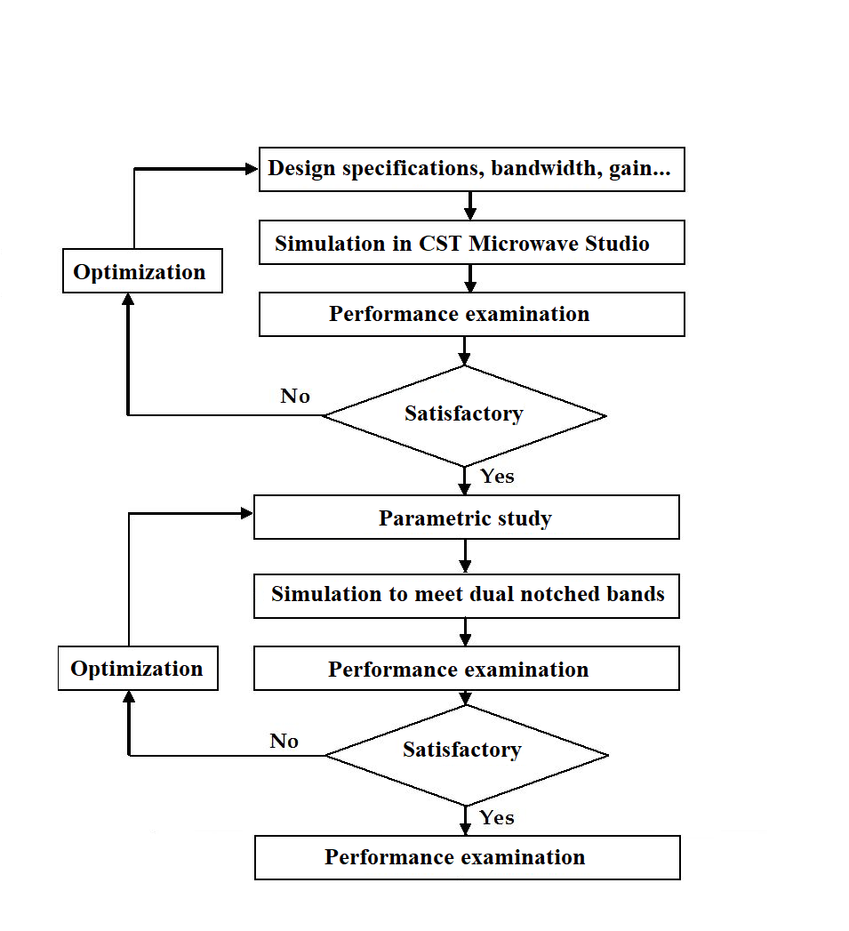 Figure 2 Flow chart of the CPW-fed Ultra-wideband antenna
3. Results and Discussions
Evidently, the simulation results provide a broadband with a -10dB from 7 to 9.9 GHz with two resonant frequencies at 7.65 and 9 GHz, respectively. Figure 3 illustrates the simulated reflection coefficient of the antenna. Apparently, the above achieved bandwidth covers the entire UWB spectrum for X-band applications.
The simulated result of our UWB antenna with and without slots is shown in Figure 4. The slots are made on the radiating element to get rid of the notched band.
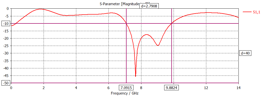 Figure 3 Simulated reflection coefficient of the propounded antenna
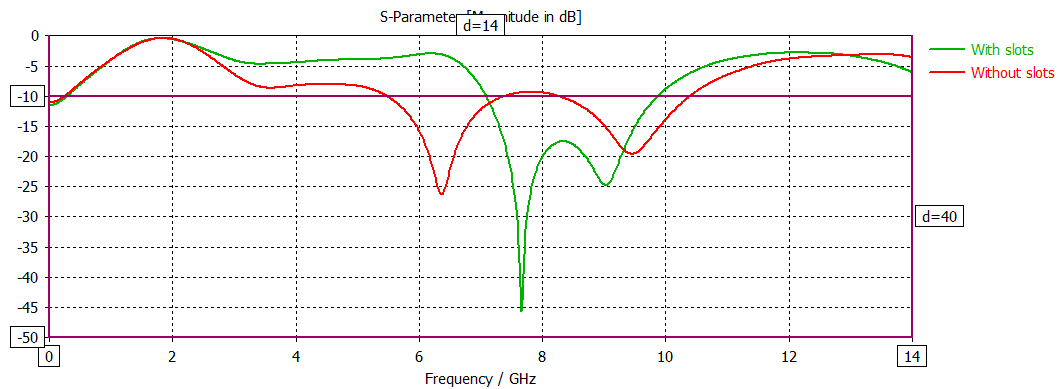 Figure 4 Simulated reflection coefficient of the propounded antenna with and without slots
By analyzing the effect of the width and the length of the slot in the radiating element, we aimed to determine the optimum parameters of the slot to achieve the right bandwidth for X-band applications. Figure 5 reveals the impact of the width “d” of the slot on the simulated reflection coefficient of the antenna. It may be noticed that the bandwidth increase as the width increases from 0 to 2mm to match with the X-band. Therefore, the slot width was fixed at 2 mm. Figure 6 illustrates the impact of the length “c” on the simulated reflection coefficient of the antenna. It can be seen that the suitable value of the slot length to match with X-band is 0.5mm. Higher return loss parameter values are observed when slot length increases from 0.5 to 0.75 mm. In summary, by reasonable selection of the length and width of the slot, we can obtain the desired bandwidth. Therefore, we decided on c=0.5mm and d=2mm as the optimum values of the slot.
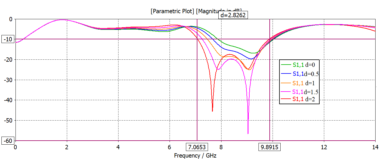 Figure 5 Simulated reflection coefficient response of the propounded antenna as a function of “d”. All remaining parameters are identical to those in Table 1.
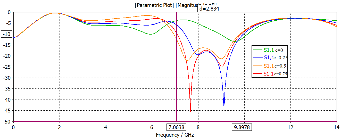 Figure 6 Simulated reflection coefficient response of the propounded antenna as a function of “c”. All remaining parameters are identical to those in Table 1.
Regarding the radiation properties of the concept model, the antenna has quasi-invariant radiation characteristics, which is confirmed on the basis of the three-dimensional radiation patterns of the simulations in Figure 7.
From the Figure 8, that presents the E-Plane (XZ plane, Phi=0) radiation patterns at7.65 GHz and 9 GHz, the antenna has an approximate unchanged radiation pattern and the results match the characteristic of UWB systems, which should be possible to receive information signals from all directions. Furthermore, this is supported by the same diagrams of the surface current distributions in Figure 9.
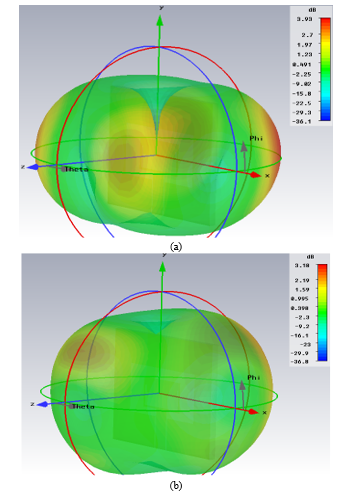 Figure 7 3D radiation patterns of the propounded antenna at (a) 7.65 and (b) 9 GHz.
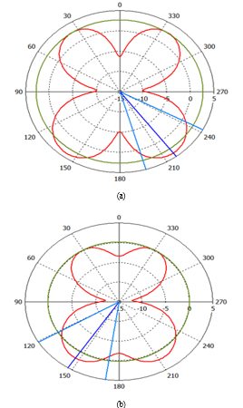 Figure 8 E-field radiation patterns of the antenna (XZ; Phi=0) at (a) 7.65 GHz and (b) 9GHz
The current distribution over the antenna with slots is shown in Figure 9 at the two resonant frequencies (a) 7.65 and (b) 9 GHz. It can be seen that the current density is highly condensed at the edges of the slots. The currents flow from the feed point of the antenna to the upper part of the radiating element on the same channel for the two resonant frequencies. The current distributions flow principally through the transmission line. Patently, the distribution of the surface current is symmetric over the antenna.
Figure 10 illustrates the radiation efficiency of the CPW-fed UWB antenna. A maximum radiation efficiency of 83% and more than 79% throughout the entire frequency range is achieved by the antenna.
The evaluation of the antenna’s performance compared other UWB antennas is demonstrated in Table 2 in terms of their dimensions, bandwidth, gain and applications, in order to support the concept of design. It is found that the propounded antenna shows broad bandwidth impedance, small size, and high gain characteristics which make the antenna appropriate for use in UWB applications, especially X-band applications.
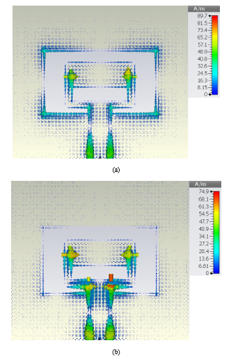 Figure 9 Surface Current distributions at (a) 7.65 GHz and (b) 9 GHz.
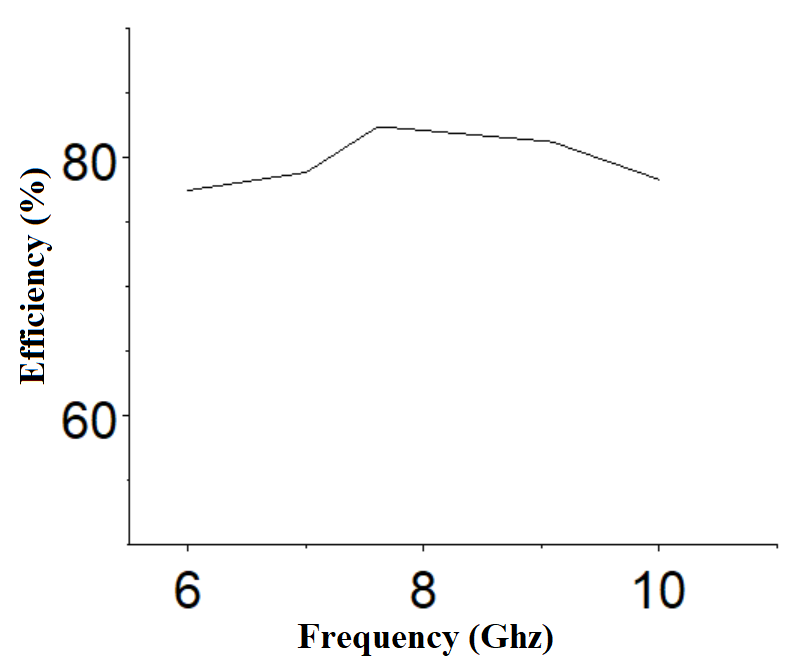 Figure 10 Simulated radiation efficiency of the propounded CPW-fed UWB antenna
Table 2: A summary of the propounded antenna and other previously released work.
| References | Dimensions
(in mm) |
Bandwidth
UWB |
Gain at resonant frequency (dB) | Applications |
| [19] | 30×29 | 5.5-12.5 | 5 | UWB applications
(C-X-band) |
| [20] | 150×150 | 4.5-7.47 | 5
|
UWB applications
(S-X-band) |
| [21] | 20×35 | 8.15-9.08 | ‘.46 | UWB applications (X-band) |
| Our work | 30×35 | 7- 9.9 | 3.18
3.93 |
UWB applications (X-band) |
4. Conclusion
An ultra-wide band (UWB) printed antenna (PMA) powered by a compact coplanar waveguide (CPW)-fed is proposed. The antenna having a total size of 30 x 35 mm² is printed on an inexpensive dielectric substrate named FR-4. The above conception skills are presented to achieve broad bandwidth supported by good impedance matching as well as constant radiation characteristics throughout the entire operating band (7-9.9 GHz). An analysis of the width and the length of the slots in the radiating patch has been given. The antenna design has been assessed through many numerical simulations. Therefore, the propounded antenna is supposed to be a strong competitor for a variety of UWB systems, especially for X-band applications.
- Federal Communications Commission (FCC) “New Public Safety Applications and Broadband Internet Access among Uses Envisioned by FCC Authorization of Ultra-Wideband Technology”, February 2002.
- Federal Communications Commission (FCC), “Revision of Part 15 of the Commission’s Rules Regarding Ultra-Wideband Transmission Systems”, First Report & Order, Washington DC, February 2002.
- Naghshvarian Jahromi, A. Falahati and R.M. Edwards, “Application of fractal binary tree slot to design and construct a dual band-notch CPW-ground-fed ultra-wide band antenna”, IET Microwaves, Antennas & Propagation, Vol. 5, pp. 1424-1430, 2011. DOI: 10.1049/iet-map.2011.0025
- Shen, C.L.Law, and Z. Shen “A CPW-fed circularly polarized antenna for lower Ultra Wideband application,” Microwave Opt. Technol. Lett.,Vol. 51, No. 10, Oct. 2009. https://doi.org/10.1002/mop.24629
- Hamza QADDI, Marko SONKKI, Sami MYLLYMAKI, Hassan MHARZI, M. Nabil SRIFI, and Heli JANTUNEN, “Novel compact patch antenna for Ultra-wideband (UWB) applications”, International Journal Of Microwave And Optical Technology, Vol. 13, pp. 343-350, July 2018.
- Y. Sze and S. P. Pan “Design of CPW-fed circularly polarized slot antenna with a miniature configuration,” IEEE Trans. Antennas and Wireless Propagation Lett., vol.10, pp.1465-1468, Oct. 2011. DOI: 10.1109/LAWP.2011.2179912
- Y. Sze and C. C. Chang, “Circularly polarized square slot antenna with a pair of inverted-L grounded strips,” IEEE Trans. Antennas and Wireless Propagation Lett., vol.7, pp.149-151, July 2008. DOI: 10.1109/LAWP.2008.921341
- Kharakhili, F. G., M. Fardis, G. Dadashzadeh, A. Ahmadi, and N. Hojjat, “Circular slot with a novel circular microstrip open ended microstrip feed for UWB applications,” Progress In Electromagnetics Research, Vol 68, pp. 161–167, 2007. doi:2528/PIER06071901
- Marqués, R.; Mesa, F.; Martel J.; Medina, F. “Comparative analysis of edge and broadside coupled split ring resonators for metamaterial design: Theory and experiment”. IEEE Transactions on Antennas and Propagation, Vol. 51, No. 10, pp. 2572-258, October 2003. DOI: 1109/TAP.2003.817562
- Latif, L. Shafai and S. K. Sharma, “Bandwidth Enhancement and Size Reduction of Microstrip Slot Antennas”. IEEE Transactions on Antennas and Propagation, Vol. 53, No. 3, pp. 994-1003, March 2005. DOI: 10.1109/TAP.2004.842674
- Ibrahim, M. A. Abdalla, and A. Boutejdar, “A Printed Compact Band-Notched Antenna Using Octagonal Radiating Patch and Meander Slot Technique for UWB Applications”, Progress In Electromagnetics Research M, Vol. 54, pp. 153–162, 2017. doi:10.2528/PIERM16122805
- Changzhou Hua, Yunlong Lu, and Taijun Liu, “UWB Heart-Shaped Planar Monopole Antenna with a Reconfigurable Notched Band”, Progress In Electromagnetics Research Letters, Vol. 65, pp. 123–130, 2017. doi:10.2528/PIERL16120203
- Pirooj, M. Naser Moghadasi, F. B. Zarrabi, and A Sharifi, “A Dual Band Slot Antenna for Wireless Applications with Circular Polarization”, Progress In Electromagnetics Research C, Vol. 71, pp. 69–77, 2017. doi:10.2528/PIERC16111401
- LUI, C. CHENG and H. ZHU, “Improved frequency notched ultra wideband slot antenna using square ring resonator”, IEEE Trans. Antennas Propag., vol 55, No. 9, pp. 2445–2450, 2007. DOI: 10.1109/TAP.2007.904090
- Farswan, A. K. Gautam, B. K. Kanaujia and K. Rambabu “Design of Koch Fractal Circularly Polarized Antenna for Handheld UHF RFID Reader Applications”, IEEE Transactions on Antennas and Propagation , Vol 64, No 2, Feb. 2016. DOI: 10.1109/TAP.2015.2505001
- Lakrit, H. Ammor and J. Terhzaz , “Design of H-slot Patch Antenna for Ultra Wideband”, European Journal of Scientific Research , Vol 106 No 2, pp:224-228, 2013.
- C. Wadell, Transmission Line Design Handbook. Boston, MA: Artech House, 1991, pp. 73–76.
- C. Lin and K. J. Hung, “Compact ultrawideband rectangular aperture antenna and band-notched designs,” IEEE Trans. Antennas Propag., vol. 54, pp. 3075–3081, Nov. 2006. DOI: 10.1109/TAP.2006.883982
- Abdelnasser A. Eldek, Atef Z. Elsherbeni and Charles E. Smith, “Wide-Band Modified Printed Bow-Tie Antenna With Single and Dual Polarization for C– and X-Band Applications”, IEEE TRANSACTIONS ON ANTENNAS AND PROPAGATION, VOL. 53, NO. 9, SEPTEMBER 2005. DOI: 1109/TAP.2005.851870
- Veeresh G. Kasabegoudar, Dibyant S. Upadhyay, and K. J. Vinoy, “Design Studies of Ultra-Wideband Microstrip Antennas with a Small Capacitive Feed”, International Journal of Antennas and Propagation, Volume 2007, Article ID 67503, 8 pages, 2007. http://dx.doi.org/10.1155/2007/67503
- Devesh Kumar, Manish Sharma and Sakshi Bansal , “Novel Design of Key-Shaped Fractal Antenna for UWB Applications”, 2014 Sixth International Conference on Computational Intelligence and Communication Networks, 14-16 Nov. 2014. DOI: 1109/CICN.2014.31