A Fuzzy PID-Based Cascade Control for Continuous Material Weighing Conveyor

Adv. Sci. Technol. Eng. Syst. J. 4(2), 112–118 (2019);
 DOI: 10.25046/aj040215
This article presents a nonlinear model of the continuous weighing conveyor system as considering the delay time of material transport, and then given a novel two-loop control strategy based on PID combined with fuzzy logic: inner velocity control loop and outer mass flowrate control loop. Then, two designed controllers for the velocity and mass flowrate control loops are simulated and evaluated in MATLAB. After that, experimental setup of real-time weighing conveyor system is built in the UTC’s laboratory. Finally, these controllers are installed into PLC to control the material mass flowrate following on the reference input. The simulation and experimental results show that the proposed fuzzy-PID algorithm is right and able to improve the material mass flowrate control quality in industrial continuous weighing conveyor system using PLC controller.
1. Introduction
The continuous material weighing conveyor is an automatic weighing machinery, used to weigh the particulate materials in the form of a continuous stream. These weighing conveyors are used for continuous transport of the solid particulate materials in industries, such as: mining and quarrying, building materials, beverage and food processing, power generation, agricultural, pharmaceutical. These weighing conveyors may be incorporated into the conveying line to obtain a mass feed rate in a continuous process or totalized mass material delivered. The mass flow rate of material is deduced from two distinct measurements: the velocity of the conveyor and the average linear density of the material (mass per length) contained within the weigh length (the length of a conveyor section installed weigh frame with load cell sensor [1]). Consequently, the weighing conveyor performance depends not only on the conveyor velocity control loop, but also on the material mass flow control loop.
The weight feeder system is presented in [2] with a dedicated controller to control material at a specified rate, and then it is applied in many fields, such as processing industry [3], cement industry [4] and so on. Sato and Kameoka [5] proposed the generalized minimum variance control method to minimize the variance of discharged material. Then, Sato [6] applied the generalized predictive control to improve the quality of the weight control conveyor. Recent studies [7-9] focus on applying modern control techniques, such as combining PID with PSO algorithm to achieve optimal PID parameters, close to industrial weighing process. The studies [10,11] present fuzzy logic-based control method that mimics PID control rules or use fuzzy logic to adjust PID parameter to overcome some nonlinear characteristic of weighing conveyor.
The majority of these studies [2-11] only mention the conveyor velocity control loop with acceptable control quality but have not consider to the fact that output mass flow control of the conveyor must be attached according to the production technology trajectory (for material mass flow control problem). Moreover, the only-velocity-control-loop can cause large mass difference when conveyor runs at high velocity, or when hopper’s material varies greatly (source of input materials).
This article presents a novel cascade control strategy for the continuous weighing conveyor based on PID control and fuzzy logic with two-loop-control-structure: inner-velocity-control-loop and outer-mass-flowrate-control-loop. The PID parameters are synthesized based on the identified velocity control object. Then, the fuzzy logic block was developed to adjust the PID parameters of the material mass flowrate control loop according to the input reference, based on the output error and the output error differential. The parameters of this controller can be assigned directly to PLC instructions to stabilize the material mass flowrate according to the input reference. The rest of this article is organized as follow. Section 2 introduces the structure and operation principle of the weighing conveyor. Section 3 deals with the design of controllers for material weighing conveyor. Section 4 presents the experimental setup of the real-time weight system. And then, the experimental results are discussed in section 5. Finally, section 6 presents conclusions.
2. Structure and operation principle of the weighing conveyor
2.1. Description of continuous weighing conveyor
Figure 1 describes the basic components of a continuous weighing conveyor, are built to test the research result in this article, including: (1)-material hopper, (2)-weighing table, (3) loadcell, (4)-conveyor motor, (5)- loadcell signal amplifier, (6)- PLC controller, (7,8)-power converter, (9)-DC source, (10)-control panel, (11)-PLC cable, (12)-PC for monitoring.
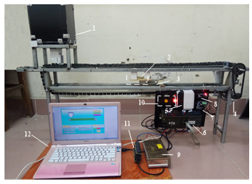 Figure 1. Structure of continuous weighing conveyor
This weighing conveyor system has the follows basic parameters: conveyor length 1000[mm], conveyor velocity 0.2[m/s], material’s mass flowrate 1.0[kg/s], weighing table length 100[mm], roller diameter 26[mm]. Conveyor drive by EXCEM DC motor with capacity 400[W], power require 24[V], maximum velocity 3000[rpm]. Measure the density of material on conveyor using a weighing table, putting on OBU loadcell with power supply 10[V], capacity 10[kg], rated output 2±10%[mV/V]. The velocity of conveyor is measured by LPD3806 rotary encoder with a DC operating voltage of 5-24[V], resolution 100[pulse/rotation].
2.2. Weighing conveyor block diagram
Material mass flowrate on weighing conveyor is determined by simultaneously measuring two parameters: conveyor velocity (v [m/s]) and material density (g [kg/m]). The control of material mass flowrate on conveyor following on reference input is done by adjusting conveyor velocity, as shown in Figure 2.
Types of solid grain materials (grain coal, small rocks, cement concrete, corn grain, rice and so on) contain in hopper, are spread evenly on weighing conveyor to ensure uniformity in the density of materials on weighing table.
Where: EN- conveyor velocity measuring encoder, LC- material density on weighing table weight measuring loadcell, KD- weight measuring signal amplifier, HS- gearbox, DC- electric motor, BD- power converter for motor, PLC- controller (ADC- analog/digital converter, HSC- high velocity counter, PWM- pulse width modulation, ALQ- algorithm of material mass flowrate control).
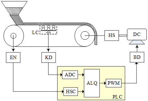 Figure 2. Schematic view of the weighing conveyor
2.3. Calculation of the material mass flowrate on conveyor
Conveyor velocity is determined by counting the numbers of pulses of the encoder attached to conveyor spindle (the conveyor always rotates follow the shaft and has no sliding phenomenon)
![]() Here: Nm[pulse]- encoder pulses on a rotation (encoder resolution); Tp[s]- pulse counting cycle; D[m]- conveyor roller diameter mounted coaxially with EN; p[pulse]- counted pulses.
Here: Nm[pulse]- encoder pulses on a rotation (encoder resolution); Tp[s]- pulse counting cycle; D[m]- conveyor roller diameter mounted coaxially with EN; p[pulse]- counted pulses.
Material density is proportional to the weight of material on the weighing table measured by loadcell [11]:
![]() Here: qw[kg]- material weight on weighing table measured by loadcell; Lw[m]- converted weighing table length, LB[m]- conveyor length between two rollers on weighing table, LA[m]- conveyor length between two rollers on feeding side, LB[m]- conveyer length between two rollers on exiting side.
Here: qw[kg]- material weight on weighing table measured by loadcell; Lw[m]- converted weighing table length, LB[m]- conveyor length between two rollers on weighing table, LA[m]- conveyor length between two rollers on feeding side, LB[m]- conveyer length between two rollers on exiting side.
The following analysis makes the simplifying assumption that any section of conveyor and the bulk material it carries is fully supported by the two closest rollers. This being the case, the full weight of product distributed on the conveyor and indeed the weight of the conveyor in the region LB of Figure 3.
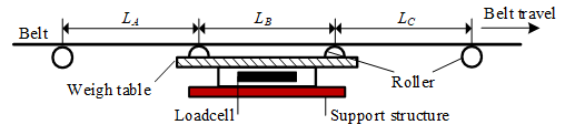 Figure 3. Schematic representation of the belt weigher
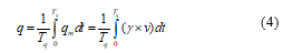
Momentary material mass flowrate on the conveyor equals to multiplication of material density and conveyor velocity, according to the following formula as:
![]() The mass flowrate of material (mass per time) is determined by multiplying the linear density (mass per length) by the velocity of the material (length per time). The velocity of the material is obtained by measuring the velocity of the conveyor and making the assumption that the material moves at the same velocity. However, care has to be taken to ensure that this is the case. The most common way of measuring conveyor velocity is through determination of the revolutions of a wheel in contact with the clean side of the conveyor.
The mass flowrate of material (mass per time) is determined by multiplying the linear density (mass per length) by the velocity of the material (length per time). The velocity of the material is obtained by measuring the velocity of the conveyor and making the assumption that the material moves at the same velocity. However, care has to be taken to ensure that this is the case. The most common way of measuring conveyor velocity is through determination of the revolutions of a wheel in contact with the clean side of the conveyor.
The actual average mass flowrate on conveyor is determined by taking the instantaneous mass flowrate integration with the integral time constant Tq[s], according to the following formula:
 3. Design of controllers for material weighing conveyor
3.1. Structure block diagram of material flowrate control system
Structure block diagram of the material mass flowrate control system on the conveyor consists of two control loops: the inner conveyor velocity control loop and the outer mass flowrate control loop, as shown in Figure 4.
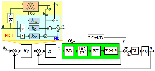 Figure 4. Structure block diagram of the weighing conveyor control system
Here: Rq– mass flowrate controller, Rv– conveyor velocity controller, BT- conveyor, DL- delay block when considering the time delay of the material transport on the conveyor, AQ- average mass flowrate calculation block, qsp– flow set point, Uv– conveyor velocity control signal, Gov– conveyor velocity control object, including BD converter based on MOSFET, motor and gearbox DC+HS, conveyor BT, encoder measuring and calculating conveyor velocity EN+KV.
Mass flowrate controller Rq is designed based on the principle of PID control law with the parameters kPF, kIF, kDF that are adjusted online by fuzzy calculating block FCQ based on initial parameters kP0, kI0, kD0 synthesized according to traditional methods.
3.2. Identify the object of the conveyor velocity control loop
Experimental diagram to identify the control object of the loop to control the conveyor velocity as shown Figure 5.
The laptop/PC (with monitoring interface based on Wincc) communicates with PLC controller. Pulse width modulation mode setting time: TPWM=1ms. To achieve the conveyor velocity characteristic, we do the following: on the computer, setting the velocity value vsp=0.2m/s; at this time, the PLC outputs feed the control pulse with time TON=TPWM., corresponding to the control signal Uv=100%. This pulse is sent to the BD power converter to fully open the MOSFET supply Udm for the DC motor and therefore the BT conveyor operates. Conveyor velocity is determined by counting number of pulses at PLC input (connected to the encoder). The characteristic of conveyor velocity is collected on the WinCC interface on the computer, as shown in Figure 6.
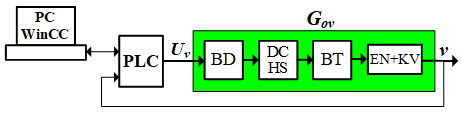 Figure 5. Block diagram for identifying object of velocity control loop
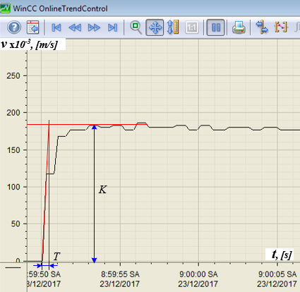 Figure 6. Response of the conveyor velocity control loop
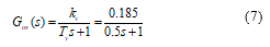
Based on the characteristic type of the velocity loop control object, allow to approximate this control object as the first order inertia object, with the transfer function as follow:
![]() Here: kv là gain coefficient; Tv inertial time.
Here: kv là gain coefficient; Tv inertial time.
From graph on Figure 6, to determine Tv, drawing the tangent to the characteristic, the inertial time Tv can specify: Tv=0.5[s].
Gain coefficient k is determine as follow:
![]() Thus the transfer function of the velocity loop control object, in approximate form, as follow:
Thus the transfer function of the velocity loop control object, in approximate form, as follow:
 3.3. Design of the conveyor velocity controller
The block diagram of the conveyor velocity control loop is shown in Figure 7.
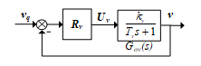 Figure 7. Block diagram of velocity control loop
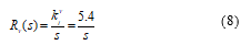
Applying the module optimal method for the conveyor velocity control object, the velocity controller is determining as the integral control law (I) with the transfer function:
 3.4. Design of the material mass flowrate controller
The approximate transfer function of the conveyor velocity control loop takes the form as:
![]() The block diagram of the material mass flowrate control loop on the conveyor, with the assumption of constant material density, taking into account the delay time of material transport on the conveyor, as shown in Figure 8.
The block diagram of the material mass flowrate control loop on the conveyor, with the assumption of constant material density, taking into account the delay time of material transport on the conveyor, as shown in Figure 8.
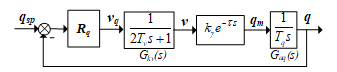 Figure 8. Block diagram of mass-flow control loop
In this diagram the parameters are as follows: kg =0.5[kg/m] is the coefficient of calculating the material mass flowrate when the velocity is in a steady state;t=1[s] is the time of material transport delay on the conveyor; Gaq(s)=1/(Tqs) is the transfer function of the material mass flowrate average calculation block, Tq=1[s].
The control object of the material mass flowrate control loop has the equivalent transfer function as follows:
![]() Applying symmetrical optimum (SO) method to the mass flowrate control object, the mass flowrate controller is determined as proportional – integral – differential control law (PID-SO) with the transfer function as follows:
Applying symmetrical optimum (SO) method to the mass flowrate control object, the mass flowrate controller is determined as proportional – integral – differential control law (PID-SO) with the transfer function as follows:
 3.5. Design of the fuzzy calculation block for the seft-tunning parameters of the mass flowrate PID controller
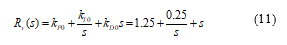
The FCQ fuzzy calculation block has two inputs: the error of the material mass flowrate EQ and the deviation differential of the material mass flowrate DEQ, corresponding to the signal e=qsp-q and the deviation differential signal de/dt. The FCQ block has three outputs, proportional coefficient-PQ, integral coefficient-IQ, the differential coefficient – DQ, corresponding to the three output values are kPF, kIF, kDF. With the above structure, the coefficients of the PID controller in combination with the fuzzy calculation block (PID-F) are determined as follows:
![]() Using the membership functions of triangles, implementing the input variables by 5 fuzzy sets {NB (Negative Big), NS (Negative Small), ZE (ZEro), PS (Positive Small), PB (Positive Big)} and output variables are equal to 5 fuzzy sets {SM (SMall), ME (MEdium), BI (BIg), QB (Quite Big), VB (Very Big)}. The physical value range of the input variables and the output variables are as follows: EQÎ[-1.0,1.0], DEQÎ[-10.0,10.0], PQÎ[0,1.0], IQÎ[0,0.01], DQÎ[0,0.5]. Based on the weight conveyor operation experience, the characteristic of the material mass flowrate control process and the PID control principle to improve the control quality for the system, the fuzzy rule table for FCQ is built as Table 1. Using the Max-Min inferential law and defuzzification according to the centroid point method, the output clear values of FCQ block kPF, kIF, kDF are defined.
Using the membership functions of triangles, implementing the input variables by 5 fuzzy sets {NB (Negative Big), NS (Negative Small), ZE (ZEro), PS (Positive Small), PB (Positive Big)} and output variables are equal to 5 fuzzy sets {SM (SMall), ME (MEdium), BI (BIg), QB (Quite Big), VB (Very Big)}. The physical value range of the input variables and the output variables are as follows: EQÎ[-1.0,1.0], DEQÎ[-10.0,10.0], PQÎ[0,1.0], IQÎ[0,0.01], DQÎ[0,0.5]. Based on the weight conveyor operation experience, the characteristic of the material mass flowrate control process and the PID control principle to improve the control quality for the system, the fuzzy rule table for FCQ is built as Table 1. Using the Max-Min inferential law and defuzzification according to the centroid point method, the output clear values of FCQ block kPF, kIF, kDF are defined.
Table 1. Fuzzy rules of the FCQ block
| PQ
IQ DQ |
EQ | |||||
| NB | NS | ZE | PS | PB | ||
|
DEQ |
NB | SM | SM | SM | SM | SM |
| NS | SM | ME | SM | SM | SM | |
| ZE | SM | SM | BI | BI | QB | |
| PS | SM | SM | BI | QB | VB | |
| PB | SM | SM | QB | VB | VB | |
3.6. Simulation of the mass flowrate control system on MATLAB
Building the material mass flowrate control system on Matlab with the Rv controller according to (8), the Rq controller has been re-calibrated with the toolbox PID Tuner so that the control quality meets the requirements, Figure 9 shows the step response of this system. The Rq controller parameters, after adjusting by toolbox PID Tuner as follows:
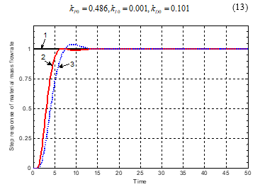 Figure 9. Step response of the weight control system: 1- reference input, 2- controller PID-F, 3- controller PID
Simulation results show that the PID controller combined with self-tuning parameters (PID-F) gives better control quality than the traditional PID controller: quick response, reduced overshoot, small steady state error, reduced the impact of noise (the level of material in the hopper).
Table 2. Quality Improvement of PID-F controller and others
| Controller
Index |
PID-F | PID-SO |
| Rise time | Small, ~5.1s | Large, ~7.1s |
| Steady time | Small, ~6.2s | Large, ~11.8s |
| Overshoot | Very small, 0.2% | Large, ~11.5% |
| Steady error | Eliminate, or very small | Small |
4. Experimental setup of the real-time weight system
4.1. Hardware wiring diagram
In this experimental system, PLC programmable logic controller Siemens S7-200 is used to install PID algorithm for velocity control loop and PID-F algorithm for the mass flowrate control loop. The equipment of the system is shown in Figure 1. The complete system is shown in Figure 10.
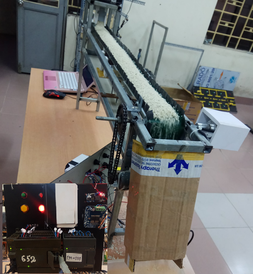 Figure 10. Experimental setup of the weighing conveyor
4.2. Algorithm for controlling material mass flowrate
The general algorithm to control the material mass flowrate for continuous weight conveyor system is shown in Figure 11.
After initializing the initial values for the system, the main program in turn calls subroutines: calculating conveyor velocity, calculating the mass of the material, calculating the material mass flowrate, calculating the error of the material mass flowrate and its deviation differential. Then the main program calls the subroutine to execute the Rq, Rv controller algorithms. Finally, the main program calls the PLC’s pulse calculation function to send to the BD converter, thereby controlling the motor velocity and thus meeting the required material mass flowrate.
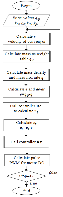 Figure 11. General algorithm for controlling mass flowrate
The algorithm for programming material mass flowrate controller Rq on PLC is shown in Figure 12.
The algorithm to program the conveyor velocity controller Rv on PLC is shown in Figure 13.
5. Experimental results
The experimental setup is shown in Figure 1, 10. In this study, the PLC S7-200 and expansion module analog EM235 are used. The laptop is communicated with PLC S7-200 through the PC Adapter USB cable to download the user program (control algorithm) into PLC S7-200 station. The output channel (PWM) from the PLC is supplied to the driver (BD) of the conveyor’s motor. The conveyor’s velocity measured by the encoder LPD3806 is fed back to the PLC via the high velocity counter input channel. The mass of materials moving on the conveyor measured by the loadcell OBU is fed back to the analog input channel of the EM235 module, after having amplified by the KD amplifier device.
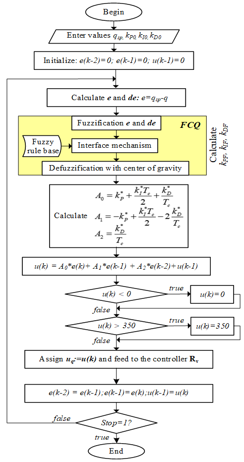 Figure 12. Algorithm of the controller Rq
The PID algorithms for the velocity control loop and the mass flowrate control loop are organized in PLC S7-200, as shown in Figure 14. The fuzzy logic calculation algorithm for adjusting PID parameters of the mass flowrate control loop is also programmed with the separate subroutine on this PLC.
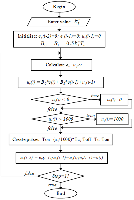 Figure 13. Algorithm of the controller Rv
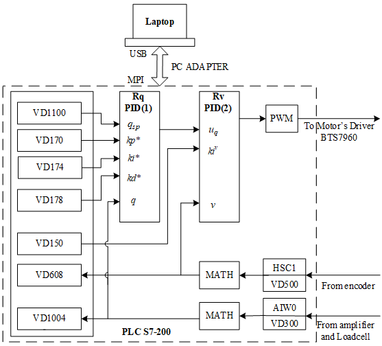 Figure 14. PID algorithms organization in PLC
The screen for monitoring the weighing conveyor was built on WinCC, as described in Figure 15.
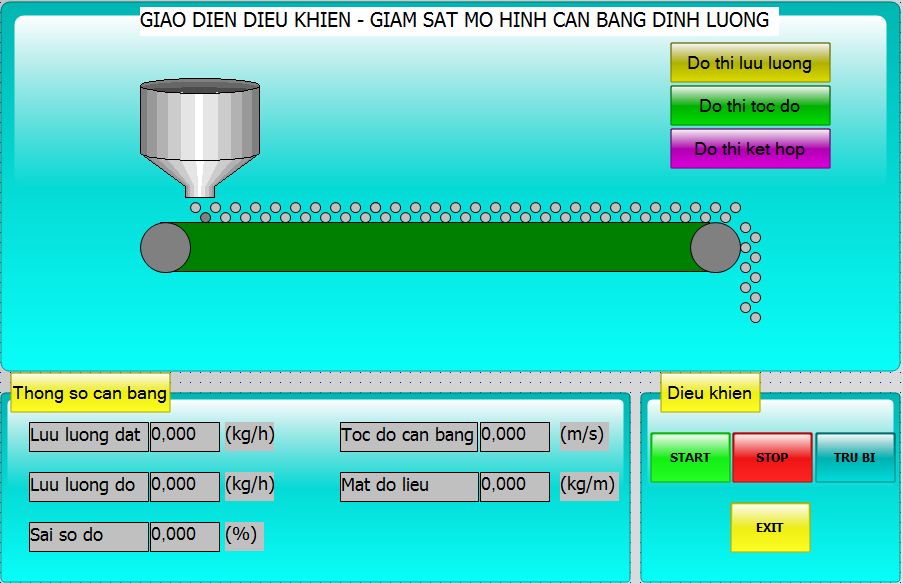 Figure 15. Screen for monitoring the weighing conveyor
This experiment was carried out with the materials – rice. The tests were done at the material’s mass flowrate qsp=80[kg/h], and qsp=100[kg/h].The experimental results with algorithm PID combined fuzzy calculating block (PID-F) to adjust the PID’s parameters are shown as Figure 16-17.
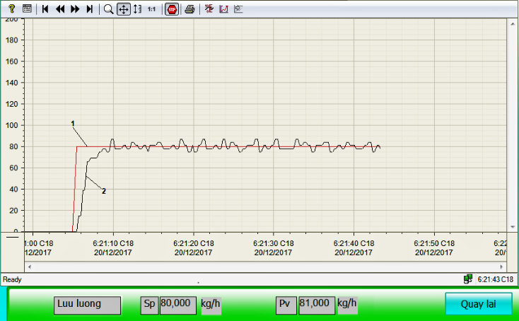 Figure 16. Real-time response of the material mass flowrate as using PLC with PID-F algorithm at qsp=80[kg/h]: 1- reference, 2- response
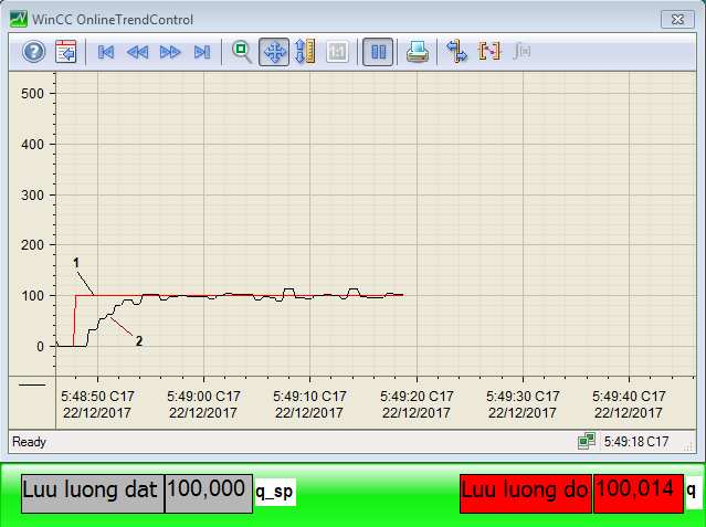 Figure 17. Real-time response of the material’s mass flowrate as using PLC with PID-F algorithm at qsp=100[kg/h]: 1- reference, 2- response
From the real-time response of the material’s mass flowrate, shows that the control object of the mass flowrate loop exits delay time with the constant delay time approximate 1 second; rising time about 5 second; after about 6.5 second, the steady state is reached; then, mass flowrate is small oscillated around the input reference. This oscillation is caused by noise measurement of the material’s mass on the conveyor by loadcell combined with the no-filter amplifier circuit.
6. Conclusion
In this article, a nonlinear model of the weighing conveyor system is developed as considering the delay time of material transport on conveyor. This is more suitable for the actual weighing process in industries. And then, a novel two-control-loop strategy is applied for controlling the material mass flowrate on conveyor. The integral control algorithm-based inner control loop is designed for the conveyor velocity object which is identified from the experimental device system at UTC’s laboratory. The outer control loop is developed for the material mass-flowrate object based on PID controller combined self-tuning parameters by the fuzzy logic calculation block. Thereafter, the proposed control strategy is verified and evaluated by simulation on MATLAB and performed experimentally on the physical equipment system at UTC’s laboratory. The experimental results show that PLC controller is capable of performing the proposed control strategy with reasonable cost, but bring better control quality, thanks to the application of advanced control techniques.
Future research focuses on improving quality of controller or/and combined with IMC, GA, GPC algorithms, as considering disturbance and applying for other materials with different density and changing parameters of the object in real time.
Conflict of interest
The authors declare no conflict of interest.
- Allgeier T., Anthony J., “A Guide to Dynamic Weighing for Industry”, The Institute of Measurement and Control, 2010.
- Hopkins M., “Loss in weight feeder systems”, Measurement + Control, 39(8), 237–240, 2006.
- Heinrici H., “Continuous weighing and feeding systems – an integral
component in process engineering”, Aufbereit Tech, 41 (8), 376–383, 2000. - Haefner H., “Advanced weigh feeder system for optimization of the kiln system”, World Cement, 27(6), 19–27, 1996.
- Sato T., Kameoka K., “Self-tuning control of a weigh feeder”, Transactions of the Society of Instrument and Control Engineers, 43(6), 522–524, 2007.
- Sato T., Design of a GPC-based PID controller for controlling a weigh feeder, Control Engineering Practice, 18, 105–113, 2010.
- Howimanporn S., Thanok S., Chookaew S., Sootkaneung W., “Speed control technique for conveyor using PSO based PID with programmable logic controller”, System Integration, 2016 IEEE/SICE International Symposium on, 670-675, 2016.
- Lakshmi V. and Srinivas P., “Optimal tuning of PID controller
using Particle Swarm Optimization”, in Proceedings of the International Conference on Electrical, Electronics, Signals, Communication and Optimization, Visakhapatnam, India, pp.1-5, 2015. - Palma B., Coito F.V., Ferreira B.G. and Gil P.S., “PSO based online optimization for DC motor speed control”, in Proceedings of the 9th International Conference on Compatibility and Power Electronics (CPE), Costa da Caparica, Portugal, pp.301-306, 2015.
- Yanan Zhao and Emmanuel G. Collins, “Fuzzy PI Control Design for an Industrial Weigh Belt Feeder”, IEEE transactions on fuzzy systems, vol. 11, no. 3, 311-319, June 2003.
- Xu-hui Chen, Md Lutfar Rahman, Yin Zhang, “Adaptive Fuzzy PID speed control of DC belt conveyor system”, 17th IEEE/ACIS International Conference on Software Engineering, Artificial Intelligence, Networking and Parallel/Distributed Computing, 2016.