Frequency-Based Design of Electric System for Off-shore Wind Power Plant (OWPP)

Adv. Sci. Technol. Eng. Syst. J. 4(2), 153–161 (2019);
 DOI: 10.25046/aj040220
The paper presents a novel concept of design of electric system for Off-shore Wind Power Plant (OWPP) based on frequency. In the literature, a new transmission system i.e. Fractional Frequency Transmission System (FFTS) has been proposed as an economic alternative to High Voltage AC (HVAC) and High Voltage DC (HVDC) for power transmission from Off-shore Wind Farm (OWF) to on-shore grid. In the FFTS power transmission is proposed at 1/3rd of conventional frequency (50Hz). The choice of this frequency (50/3Hz) for FFTS is not based on any mathematical analysis and seems to be a compromise. Since, frequency is one of the prominent parameter that reflects on the project economy, the paper explores on the choice of operational frequency for electric system in view of reduction in the investment cost. The existence of optimum frequency is realized based on the finding that, the costs of power system components are frequency-dependent and they imbibe the trade-off in their costs. The paper presents a comprehensive methodology to compute the most economical operational frequency for electric system by optimization of frequency-based cost model of the system using Genetic Algorithm (GA). The proposed methodology is applied to 160MW OWF (Horns-Rev) as a case study. For off-shore distances of 50km, 100km, 150km and 200km, the optimum operational frequencies are obtained as 52Hz, 32Hz, 22Hz and 16Hz respectively. The proposed methodology for the design of electric system based on frequency results in significant saving in the investment cost for moderate transmission distance. Hence it is concluded that, the work presented in this paper gives a new dimension for planning and cost effective design of electric system for OWPP. Further, it promotes the investor for deployment of OWF which leads to reduction in air pollution and global warming which are major concerns of the world today in the endeavor.
1. Introduction
This paper is an extension of original paper entitled, “Optimum Frequency-Based Design of Off-shore Wind Power Plant (OWPP)”, presented in 2017 IEEE PES Asia Pacific Power and Energy Engineering Conference (APPEEC), India [1]. In the present paper, the author has made an attempt to address all the comments, queries and issues raised during the publication of the previous original paper. To avoid de-linking, a brief introduction to the theme of the paper has been presented from the original work.
Harvesting energy from wind has become one of the major contributions to the energy sector across the globe. Due to policy instability as well as specific issues linked to land acquisition for wind power projects on land; deployment of wind project offshore has been increased in the recent times. High-stable offshore wind potential, large installation space, no visual effects, closeness of major load centers and technological advancement in the wind industry has supplemented its growth. Globally offshore installation has been progressed with an average growth rate of 30% per annum during 2010-2017, reaching to a total installed capacity of 18GW at the end of 2017 [2]. Opportunities for further scaling up are humongous. An ambitious target of 40GW by 2020 has been reported.
Huge initial investment is one of prominent slog in the path of offshore development. Highly evolved tower construction, offshore substation, seabed lying of submarine cable and high maintenance cost are some of reasons for heavy investment. And it is the major hindrance for offshore deployment. Presently, the Levelized Cost of Energy (LCOE) is more than $5-6 millions per MWh, and it warrants for the technological changes to reduce the investment, and make OWPP economically feasible [3].
In the OWPP, among the split-up, electrical infrastructure cost shares significant portion in the total project cost. It includes the cost of inter-farm distribution network which collects the power from the wind turbines and the cost of main transmission network which exports the power from the off-shore substation to on-shore grid. In broader perceptive, the paper exploits on opportunities to reduce the electrical infrastructure cost for OWPP.
In respect of this, a new transmission system i.e. Fractional Frequency Transmission System (FFTS) has been proposed in the literature as an economic alternative to HVAC and HVDC [4]. FFTS is also named as Low Frequency AC (LFAC) by some researchers. In the LFAC, power transmission is proposed at 1/3rd of the nominal frequency (50/60Hz), and at the grid-side, frequency converter is employed to transform fractional frequency (50/3Hz) to nominal frequency (50Hz). In the LFAC, due to low frequency operation charging current requirement of the cable is less and that increases its power transmission capacity, and unlike HVDC it requires only one converter at the grid-side are main attributes for its cost reduction [4].
The technical and economic viability of LFAC over HVDC and conventional HVAC has been investigated by many researchers [4]-[9]. It is stated that, LFAC has economic and performance advantages over conventional HVAC and HVDC and it has a future trend.
The fundamental quest on the choice 50/3 Hz frequency for LFAC has initiated this paper. Literature states that, single-phase 50/3Hz system is already in-use for supplying electric power to traction in German and in LFAC cyclo-converter can be employed for frequency transformation which is less costly compared to other converters [9]. After a careful perusal of the literature, it is revealed that, the choice of 50/3Hz frequency for LFAC seems to be a compromise, and it is not based on any rigorous mathematical analysis. The choice of frequency for power transmission is very important, because it reflects on the project economy. The original paper has dealt with the choice of operational frequency for electric system integrating OWF to on-shore grid, in view of reduction in the investment cost. Thus, a novel thought of optimum frequency-based design of OWPP had been proposed in the previous work.
In the original work, the reviewers and the panel of judges had raised the following major issues,
The first major issue was related to the methodology adopted for the computation of optimum frequency. In the previous work, optimum operational frequency was computed through optimization of the frequency-based cost model of the electric system. Genetic Algorithm (GA) was used for the optimization. Since the cost model was of single-variable (frequency), the reviewer raised the question on the applicability of GA for the optimization of a simple-single-variable model as it is applied for the case of complex system. In the present work, operating voltage of the electric system is added as another variable for enhancing optimization of the system. Furthermore, in the previous work, cost model of the system had been developed by adding frequency-based cost models of various power system components involved in the system. These cost models of the components were developed separately in the sequence. Firstly the components were designed and then from the design parameters the costs were computed for different frequencies and then from the frequency-based cost curves their cost models were derived using curve fitting techniques. The reviewer suggested combining these processes into a single execution, which is incorporated in the present work. The paper presents a newer computational structure for the computation of the optimum frequency in a single execution.
The second major issue was related to validation of the designs and cost models of the components. Design and frequency-based cost model of the transformer developed in the original paper has been validated with the models available in the literature.
The third major issue was in respect of generation of fractional frequency from the wind turbine generator. In the original work, optimization was performed on Fractional Frequency Wind Power System (FFWPS). Reference [10] has proposed this configuration for integrating OWF to on-shore grid. It eliminates individual power converter in the wind turbine and proposes speed control from single large power converter (cyclo-converter). Since the generator required in this configuration would be bulky as it has to generate low frequency power, it demands for modification in the wind turbine generator. The reviewer had questioned the implications on the design and verification with wind turbine manufacturers. Reference [10] has validated FFWPS for its practical implementation because it reduces the cost of wind turbine generator in twofold; firstly it reduces the gear ratio and secondly it eliminates the power converter. So, in the present paper, FFWPS is considered for the optimization process.
The paper is organized as follows. The structure of FFWPS and the concept of optimum operational frequency are presented in Section 2. Section 3 presents the development of frequency-based cost model of FFWPS. Section 4 presents the development of computation structure for the optimization of the developed model. Section 5 presents the rating of components of FFWPS for application of the developed methodology. The results are discussed in the Section 6 and finally Section 7 concludes the paper.
2. System model (FFWPS) and the concept of optimum frequency
Fractional Frequency Wind Power System (FFWPS) is one of the electric system configuration proposed in the literature for integrating OWF to on-shore grid [10]. Figure 1 shows the structure of this system.
In FFWPS, the entire electric system including generator, inter-farm distribution network and main power transmission network operates at 50/3Hz frequency. Frequency converter at the grid-side transforms frequency from 50/3Hz to 50Hz and the power is injected onto the grid. FFWPS eliminates the full scale power converter in the wind turbine and proposes rotor speed control from the single large power converter (cycloconverter). Due to elimination of individual power converter the cost is reduced but there is a 3% loss in the energy yield [11]. Reference [13] has discussed synchronization scheme for FFWPS and shown safe and reliable integration of offshore wind farm to onshore grid. From the literature it is revealed that, FFWPS is technically and economically suitable configuration to transmit electrical power from off-shore wind farms to the power grid.
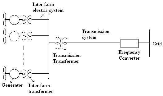 Figure 1: Structure of Fractional Frequency Wind Power System (FFWPS)
In this paper, the study on FFWPS is extended from the perspective of its operational frequency. The operational frequency of FFWPS is 50/3 Hz, but as discussed in the previous section, the choice of 50/3 Hz frequency for FFWPS seems to be compromise rather than based on any formal mathematical analysis. The paper particularly, deals with the choice of frequency (economically-optimal) for FFWPS based on the criterion of minimum investment cost.
The existence of optimum frequency for FFWPS is realized based on the finding that, the cost of power system components (generator, transformer, submarine cable, and compensator) varies with the frequency and they imbibe a tradeoff in their costs. Specifically, the cost of generator and transformer varies in inverse proportion to frequency. Because, the size of magnetic system (no. of turns/ core area) decreases with increase in frequency and hence cost decreases. Whereas, the cost of submarine cable network varies in direct proportion to frequency. Because, as the frequency increases, the charging current requirement of the cable increases, and for the same active current, the size of the conductor increases with increase in frequency and hence the cost increases.
So it is found that there is tradeoff in two broad categories of cost;
- Sum of cost of generators and transformers
- Sum of cost of submarine cable networks
Figure 2 shows the typical variation of these two costs with respect to frequency. The system cost, which is sum of these two costs, will be parabolic in nature with respect to frequency. The point of inflection on the system cost curve corresponds to the optimum point.
The X and Y co-ordinates of the optimum point corresponds to optimum operational frequency and the optimum cost respectively. The cost of generator and transformer are independent of off-shore distance, but the cost of transmission system depends upon the off-shore distance. So the point of inflection and hence the optimum cost and optimum frequency changes with the distance. Hence it is realized that, for the given power rating and off-shore distance of FFWPS, the system investment cost is a function of frequency and it get optimized (minimized) at certain economically-optimum frequency.
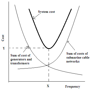 Figure 2 Show the concept of optimum frequency
3. Development of mathematical model
It is evident from the former discussion that, for a given FFWPS, the optimum operational frequency can be determined by optimizing its system cost. It represents an optimization problem. The system cost is sum of the cost of generators, inter-farm transformers, inter-farm electric system and transmission system. Mathematically, it is described as below,
The objective function is defined as,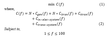
N- no. of wind turbines in the farm, Cgen(f)-cost of generator, Citran(f)- cost of inter-farm transformer, Cttran(f)- cost of transmission transformer, Cin-elec-system(f)- cost of inter-farm electric system, Ctrans-system(f)- cost of transmission system.
The cost of frequency-converter which is independent of frequency, and the cost of other equipments simply act as an offset, so they are not included.
The cost of generator, inter-farm transformer, transmission transformer, inter-farms electric system and transmission system are estimated as follows.
3.1 Estimating Generator cost
The cost of the generator is estimated from its design parameters. Since the design parameters and hence the cost are subjective to design constants (variables).To obtain economy, the generator-cost is optimized in terms of its design variables. Specific magnetic loading (Bav), specific electric loading (ac), width of ventilating duct (wds), width of stack length (wss), slot pitch (ys), current density (δ) and Short Circuit Ratio (SCR) are selected as design variable with appropriate bonds. Copper and iron are major elements in the generator. So the cost of generator is estimated by considering only the cost of copper and iron. Mathematically it is described as below,
The objective function is defined as,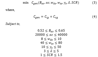
Cgen – cost of generator, Cig – iron cost, Ccg – copper cost.
Cost of iron and copper is estimated from the volume of iron and copper, which are calculated from the main dimensions, number and size of stator slots, depth of stator core, dimension of rotor pole, depth of rotor core and number of stator and rotor turns.
3.2 Estimating Inter-farm transformer cost
The cost of the transformer is estimated from its design parameters. Since the design parameters and hence the cost are subjective to design constants (variables). To obtain economy, the transformer-cost is optimized in terms of its design variables. A constant (K), as defined in Equation (6) is selected as design variable.
Cost of copper and iron are only considered for estimating the cost of transformer. Mathematically it is defined as below,
The objective function is defined as,![]()
where,
– transformer cost (M €), – iron cost (M €), – copper cost (M €).
Cost of iron and copper is estimated from the volume of iron and copper, which in-turn are calculated from the core area, primary and secondary turns and width and height of core.
3.3 Estimating Transmission transformer cost
The cost of transmission transformer is estimated as similar to inter-farm transmission transformer (discussed above).
3.4 Estimating Inter-farm electric system cost
The inter-farm electric system includes the interconnection of wind turbines in the farm by submarine cables. The cost of inter-farm electric system is estimated as per by Equation (9). It includes only the cost of copper core. As per the standard practice, size of the core is assumed 50% more than the actual requirement.
where,
I – net current to be carried by the cable/phase (amps) , – current density (amp/m2), L – length of the cable (m), Sc– specific cost of copper (/kg), Dc –density of copper (kg/m3).
The net current is calculated by adding the active current and the charging current as per Equations (10)-(12). ![]()
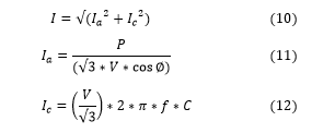
where,
Ia – active current /phase(amps), Ic – charging current/phase(amps), P – 3-phase power (W), V – line-to line voltage (V), cosφ – power factor of load, f – frequency (Hz), C – Capacitance of the cable (F).
3.5 Estimating Transmission system cost
The transmission system exports power from local off-shore grid to on-shore grid by submarine cable. Its cost is estimated as similar to inter-farm electric system (discussed above).
4. Implementation of mathematical model
The mathematical model developed in the previous section, describes the requirement of optimization of system cost model to determine optimum operational frequency. Further, to achieve overall economy, it demands for optimal design of generator and transformers. To implement this, a computational structure with two-stage optimization is developed as shown in the Figure 3. In the first-stage (stage-I), the cost of generator, inter-farm transformer and the transmission transformer are optimized in terms of their design variables, whereas, the system cost is optimized in terms of frequency in the second-stage (stage-II).
This unique feature ensures over-all optimization of the problem. Genetic Algorithm (GA) is used for all the optimizations.
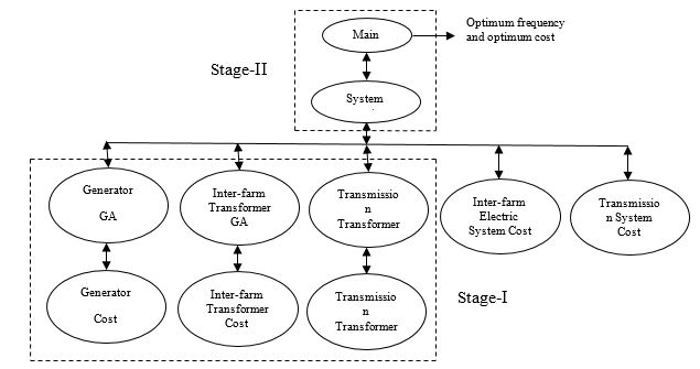 Figure 3: Computational structure of optimization
Figure 4 depicts the process of computation of optimum operational frequency. For simplification, working of Main-GA is only presented. The size of population (fre_pop_max)) for variables (frequency and voltage) and maximum generation limit (gen_max) are set to 50 and 100 respectively. The main core of the algorithm is the evaluation of fitness values (system costs). Initially the population for frequency and voltage is generated randomly. Then, the fitness values are evaluated for each of the population by adding the cost of power system components, which are computed from the executions of respective subroutines. The population is improvised through reproduction, crossover and mutation process and the iteration of generation is continued till the maximum generation count is reached.
Then finally, the minimum fitness value of the last generation which corresponds to the optimum cost is evaluated. The population corresponding to the optimum cost is the optimum frequency.
This methodology of computation of optimum frequency through single-execution effectively addresses all the issues raised by the reviewers in the original paper.
Table 1: Rating of various components of OWPP
| Component | Rating |
| Generator | EESG: 2MVA, 690V, 35rpm |
| Inter-farm transformer | 3-phase, core type: 2MVA, 0.69/33kV. |
| Inter-farm electric system | Submarine cable: 33kV,100km |
| Transmission Transformer | 3-phase core type: 160MVA, 33/150kV |
| Transmission system | Submarine cable: 160MW,150kV, varying length |
5. Results and discussions
Based on the computational structure and the flow chart presented in the previous section, code is written in MATLAB-7.The ratings of power system components are initialized as per the prototype FFWPS. The code is executed under different scenarios to obtain the following results.
5.1 Validation of the generator and transformer design
Electrically Excited Synchronous Generator (EESG) of 2MVA, 690V, 35 rpm is designed using Genetic Algorithm for different frequencies. Table 2 in Appendix, shows the design and performance parameters. Similarly, Table 3 in Appendix shows the design and performance parameters of 3-phase, core type, 2MVA, 0.69/33kV transformer designed using Genetic Algorithm. It can be seen that, core and copper volume for generator and transformer increases with decrease in frequency and hence the cost increases, it complies with the fundamental fact that, the size of the magnetic system increases with decrease in frequency. Since only the cost of iron and copper are taken into account in estimating the cost, the figures given in the tables do not reflect the real costs. Further, since the feasibility of frequency-based design of electric system is evaluated in comparison to LFAC and HVAC, only qualitative variation in the cost with respect to frequency is needed.
5.2 Verifying the existence of optimum frequency
It was postulated in the Section 2 that, the system cost is parabolic in nature w.r.t. frequency and the co-ordinates of the optimum point corresponds to the optimum cost and the optimum operational frequency. To investigate this phenomenon, prototype FFWPS with 50km off-shore distance is considered. The cost of power system components and the system cost are estimated for different frequencies. Table 4 gives the variation in the costs w.r.t. frequency. It can be seen that, the cost of generator, inter-farm transformer and transmission transformer decreases with increase
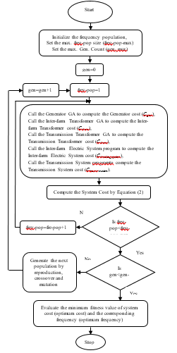 Figure 4: Flow chart showing working of computational structure
in frequency, whereas the cost of inter-farm electric system and transmission system increases with increase in frequency. It can also be seen that, the system cost decreases initially up-to certain optimum frequency (indicated by shading) and then increases with the frequency. Figure 5 shows the system cost w.r.t. frequency. It can be seen that, the cost of FFWPS is parabolic in nature and their lies an optimum operational frequency where the system cost is minimum. For 50km transmission length, the optimum operational frequency is obtained as 52Hz and the corresponding optimum cost is 64.73M€. If the system is operated at 50/3Hz, the system cost will be 78.43M€. Thus the result clearly indicates that, if the FFWPS is operated at optimum operational frequency rather than operating at 50/3Hz, substantial amount of saving can be achieved. Figure 6 shows the savings for different frequencies. It can be seen that; the saving is maximum (17.47%) at the optimum operational frequency. Thus it is verified that, for the given FFWPS, there exist an optimal operational frequency.
Table 4: Variation in the cost of various power system components w.r.t. frequency
| (1) | (2) | (3) | (4) | (5) | (6) | (7) |
| 50/3 | 21.31 | 8.12 | 19 | 0.78 | 29.21 | 78.43 |
| 20 | 18.25 | 6.75 | 19.14 | 0.68 | 29.31 | 74.14 |
| 30 | 13.39 | 4.58 | 19.7 | 0.52 | 29.7 | 67.89 |
| 40 | 10.75 | 3.5 | 20.45 | 0.42 | 30.25 | 65.37 |
| 52 | 9.22 | 2.84 | 21.38 | 0.35 | 30.94 | 64.73 |
| 60 | 8.2 | 2.43 | 22.46 | 0.31 | 31.77 | 65.18 |
| 70 | 7.56 | 2.11 | 23.68 | 0.28 | 32.72 | 66.34 |
| 80 | 6.99 | 1.86 | 25.01 | 0.26 | 33.78 | 67.9 |
| 90 | 6.51 | 1.68 | 26.43 | 0.24 | 34.95 | 69.8 |
| 100 | 6.05 | 1.59 | 27.94 | 0.22 | 36.21 | 72.01 |
(1)- Frequency (Hz), (2)- Generator cost (M€), (3)- Inter-farm transformer cost (M€), (4)- Inter-farm electric system cost (M€), Transmission transformer cost (M€), (5)- Transmission system cost (M€), (7)- System cost (M€)
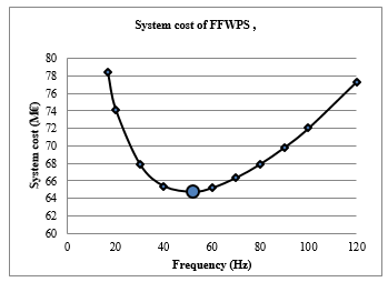 Figure 5: Variation in cost of FFWPS v/s frequency (off-shore distance 50km)
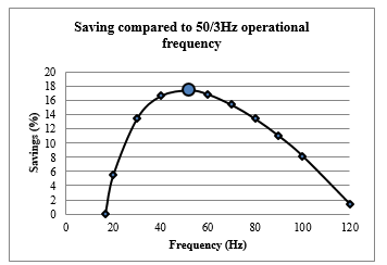 Figure 6: Saving with optimum design in comparison to LFAC (off-shore distance 50km)
Further, since the optimum operational frequency depends upon the off-shore distance. With the aid of Main-GA, optimum operational frequencies for different transmission lengths are obtained as shown in the Figure 7. It can be seen that, the optimum operational frequency decreases with increase in the transmission length. It complies with the fact that, HVAC (50 Hz) is economical for short distance transmission and HVDC (0 Hz) is for long distance.
5.1. Feasibility of optimum frequency-based design
As stated earlier, the main objective of paper is to enhance the project economy by reducing its electric infrastructural cost through its operation at optimum frequency. To investigate this, savings accrued from optimum frequency-based design, in comparison to conventional HVAC (50Hz) and LFAC (50/3Hz) are estimated as shown in the Figure 8 for different transmission lengths.
The saving is expressed as percentage of the cost of system under comparison. It can be seen that, compared to LFAC, optimum frequency-based system gives substantial amount of saving in the investment cost up-to 150km (approx.). Whereas, compared to HVAC, the saving is substantial beyond 80km (approx.). So, when it is question of choice of system, the results indicates that, HVAC is undoubtedly better up-to 80km distance, but beyond that and up-to 150km, optimum frequency-based system is a promising choice. The results suggest that, for the given FFWPS, optimum frequency-based system is feasible for the off-shore distance in the range of 80-150 km, and for this range the operational frequency is 20 to 40 Hz.
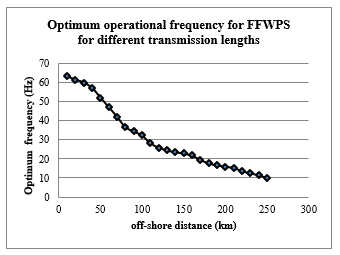 Figure 7: Optimum operational frequencies for FFWPS for different off-shore distances
5.2 Consideration of optimum operating voltage
The savings shown in the Figure 8 are obtained with fixed operating voltages i.e. 33kV for inter-farm electric system and 150kV for transmission system. But the savings can be enhanced enormously if the operating voltages are selected appropriately. The basic thumb rule recommends for the selection of highest possible operating voltages. Even-though, higher operating voltage reduces the cost of inter-farm electric system and transmission system, but on contrary, they increase the cost of inter-farm transformer and transmission transformer.
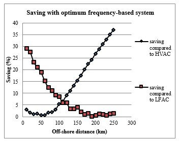 Figure 8: Saving with optimum frequency-based system
So there is trade-off in the costs and it demands for optimum selection of operating voltages.
To address this issue, the operating voltages of inter-farm electric system and transmission system are initialized as variables in the optimization (Main-GA) along with frequency. This leads to an idea of optimum frequency-voltage-based design of FFWPS. Figure 9 shows the saving accrued from this system compared to HVAC and LFAC. For HVAC and LFAC system the operating voltages are kept fixed as before.
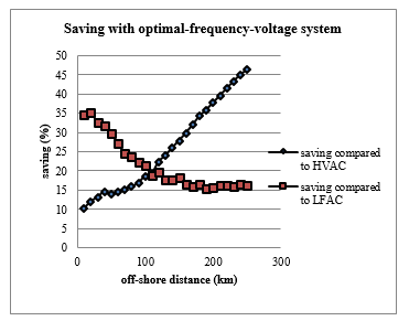 Figure 9: Saving with optimum-frequency-voltage system
It can be seen that the savings are augmented by optimum selection of operating voltages along with optimum choice of operational frequency.
Thus the results reveal that, there exits an optimum operational frequency and if the electric system is designed and operated at the optimum frequency rather at the standard conventional frequencies, substantial amount of saving in the investment can be achieved.
6. Conclusions
The paper has extended the work on optimum frequency-based design of electric system for OWPP. It deals with the computation of most economical operational frequency so that the electrical infrastructural cost is minimal. The paper has presented a newer methodology for the optimal design of electric system through optimization of frequency-based cost model of the system in a single execution. The developed methodology is applied to a prototype FFWPS and shown that the investment cost can be reduced significantly if the system is designed and operated at the optimum frequency. Further, the paper effectively addresses all the issues of the original paper. It is concluded that, the proposed optimal design for electric system is economically competitive compared to HVAC and LFAC for moderate transmission distance. The work carried out in this paper provides a new dimension for economical design of electric system. It also helps in motivating the investors for deployment of OWF to dovetail the energy gap between generation and demand. Further it also indirectly addresses the problem of environment pollution and global warming which are the major concerns of world today in the endeavor. Nevertheless in the proposed design, power system components such as generator, transformer and compensation units need to be redesigned for the operation at nonconventional frequencies. But for large size wind farms (>1000MW), it will not be major paramount because the required generators and transformers can be manufactured cheaply in mass. In the present paper only investment cost is considered for the optimal design but in the future work operational cost can also be added in the optimization to get better results. Further, the study can be extended to other configurations of electric system.
Appendix
Table 2: Design and performance parameters of 2MVA, 690V, Salient pole Synchronous Generator
| Design and performance
parameters |
5Hz | 10Hz | 50/3Hz | 20Hz | 25Hz | 30Hz | 35Hz | 40Hz | 45Hz | 50Hz |
| Optimal Cost (M €) | 0.7355 | 0.4152 | 0.2661 | 0.2291 | 0.1935 | 0.1689 | 0.1490 | 0.1360 | 0.1258 | 0.1166 |
| Stator Bore Diameter (m) | 3.9244 | 4.5426 | 5.2074 | 5.5080 | 5.8600 | 6.2130 | 6.4700 | 6.7840 | 6.9900 | 7.2640 |
| Stator Length (m) | 0.8219 | 0.6205 | 0.4674 | 0.4220 | 0.3760 | 0.3370 | 0.3080 | 0.2842 | 0.2649 | 0.2481 |
| Poles | 18 | 34 | 58 | 70 | 86 | 104 | 120 | 138 | 154 | 172 |
| Turns/pole | 51 | 56 | 66 | 69 | 72 | 77 | 80 | 85 | 86 | 88 |
| Flux/pole (wb) | 0.3655 | 0.1668 | 0.0849 | 0.0677 | 0.0519 | 0.0404 | 0.0334 | 0.0275 | 0.0242 | 0.0213 |
| Volume of stator iron (m3) | 1.8363 | 0.8836 | 0.4656 | 0.3753 | 0.2871 | 0.2267 | 0.1791 | 0.1484 | 0.1259 | 0.1060 |
| Volume of stator copper (m3) | 0.2026 | 0.1624 | 0.1482 | 0.1426 | 0.1363 | 0.1345 | 0.1320 | 0.1329 | 0.1281 | 0.1258 |
| Volume of rotor iron (m3) | 3.3626 | 1.8963 | 1.1727 | 0.9993 | 0.8236 | 0.6951 | 0.6032 | 0.5330 | 0.4825 | 0.4446 |
| Volume of rotor copper (m3) | 0.2841 | 0.2210 | 0.1982 | 0.1805 | 0.1720 | 0.1681 | 0.1571 | 0.1527 | 0.1520 | 0.1430 |
| Loss (MW) | 0.4197 | 0.2839 | 0.2289 | 0.2118 | 0.1833 | 0.1739 | 0.1632 | 0.1585 | 0.1539 | 0.1485 |
| Efficiency (%) | 79.400 | 85.100 | 87.910 | 88.840 | 89.670 | 90.170 | 90.690 | 90.940 | 91.230 | 91.540 |
| Stator temp rise (0c) | 196.05 | 141.89 | 107.00 | 98.210 | 88.720 | 77.610 | 75.970 | 68.350 | 66.194 | 64.250 |
| Rotor temp rise (0c) | 236.32 | 214.99 | 190.32 | 188.73 | 174.63 | 164.77 | 160.75 | 159.32 | 144.42 | 144.54 |
Table 3: Design and performance parameters of 2MVA, 0.69/33kV, 3-phase core type transformer
| Design and performance
parameters |
5Hz | 10Hz | 50/3Hz | 20Hz | 25Hz | 30Hz | 35Hz | 40Hz | 45Hz | 50Hz |
| Optimal Cost (M €) | 0.2350 | 0.1447 | 0.0999 | 0.0838 | 0.0678 | 0.0571 | 0.0496 | 0.0434 | 0.0391 | 0.0354 |
| Constant (k) | 0.1150 | 0.1524 | 0.3353 | 0.3556 | 0.3830 | 0.4064 | 0.4350 | 0.4427 | 0.4669 | 0.4801 |
| Core area (m2) | 0.1544 | 0.1023 | 0.1351 | 0.1194 | 0.1029 | 0.0910 | 0.0835 | 0.0743 | 0.0697 | 0.0645 |
| Primary turns | 77 | 60 | 28 | 25 | 25 | 24 | 24 | 21 | 21 | 21 |
| Secondary turns | 3705 | 2795 | 1275 | 1200 | 1100 | 1050 | 975 | 950 | 900 | 875 |
| Width of transformer (m) | 1.9492 | 1.5867 | 1.8230 | 1.7138 | 1.5907 | 1.4960 | 1.4328 | 1.3521 | 1.3092 | 1.2594 |
| Height of transformer (m) | 1.3875 | 1.1294 | 1.2977 | 1.2199 | 1.1323 | 1.0648 | 1.0199 | 0.9624 | 0.9319 | 0.8965 |
| Volume of core (m3) | 6970 | 3760 | 5700 | 4730 | 3790 | 3150 | 2770 | 2330 | 2110 | 1880 |
| Volume of copper (m3) | 6180 | 4230 | 439 | 400 | 359 | 338 | 317 | 309 | 269 | 266 |
| Loss (MW) | 0.1258 | 0.0831 | 0.0717 | 0.0614 | 0.0549 | 0.0513 | 0.0431 | 0.0469 | 0.0407 | 0.0395 |
| Efficiency (%) | 92.7658 | 95.066 | 95.858 | 96.311 | 96.661 | 96.895 | 97.380 | 97.153 | 97.519 | 97.500 |
| Regulation (%) | 4.5138 | 3.4294 | 19.519 | 21.298 | 26.561 | 32.104 | 21.080 | 49.623 | 38.329 | 47.159 |
| No-load current as % of
full load current (%) |
7.2447 | 5.9768 | 11.522 | 12.000 | 11.134 | 10.882 | 12.368 | 9.8491 | 10.792 | 10.386 |
- Uttam S. Stpute, D.R. Joshi, “Optimum Frequency-Based Design of Off-shore Wind Power Plant (OWPP)”, proc. of 2017 IEEE PES Asia-Pacific Power and Energy Engineering Conference (APPEEC), Bengaluru, India, Nov. 2017.
- ‘Global Wind Energy Council (GWEC) global 2015 report’, available at : http://www.gwec.net/global, visited on: 25th August 2018.
- Yuan-Kang Wu, Li Wang, Yong-Qing Huang, Shu-Wei Liu, “Overview of Important State-of-the-art Technologies in Off-shore Wind Energy System,” International Journal of Smart Grid and Clean Energy, vol. 2, no. 2, pp. 64-67, May 2013.
- X. Wang, “The fractional frequency transmission system,” in Proc. IEEE 5th Annu. Conf. Jpn. Power Energy, Tokyo, Japan, Jul. 1994,pp 53-58.
- X. Wang and X. Wang, “Feasibility study of fractional frequency transmission system,” IEEE Trans. Power Syst., vol. 11, no. 2, pp. 962-967, May 1996.
- X. Wang, C. Cao, and Z. Zhou, “Experiment on fractional frequency transmission system,” IEEE Trans. Power Syst., vol. 21, no. 1, pp. 372-377, Feb. 2006.
- U. Satpute, S. Jangamshetty, and D. Joshi, “Feasibility study of fractional frequency transmission system,” in Proc. Joint Int. Conf. Power Electron. Drives Energy Syst., New Delhi, India, Dec. 2010, pp. 1-6.
- X. Wang, “Fractional frequency transmission system and its applications on wind power and renewable resource integration into system,” Power Elect. Eng., vol. 2, no. 1, pp. 12-14, 2008.
- W. Fischer, R. Braun and I. Erlich, “Low frequency high voltage offshore grid for transmission of renewable power”, proc. of 3rd IEEE PES Innovative SmartGrid Technologies Europe, Berlin, Oct. 2012.
- X. Wang, “Fractional frequency wind power system,” Mod. Elect. Power, vol. 24, no. 1, p. 1, 2007
- Z. Song, X. Wang, Y. Teng, L. Ning, and Y. Meng, “Optimum control study for fractional frequency wind power system,” in Proc. Asia-Pac. Power Energy Eng. Conf. Shanghai, China, Mar. 2012, pp. 1-5.
- O. Gomis-Bellmunt, A. Junyent-Ferr´e, A. Sumper, and S. Galceran-Arellano, “Maximum generation power evaluation of variable frequency offshore wind farms when connected to a single power converter,” Appl.Energy, vol. 87, no. 10, pp. 3103–3109, Oct. 2010.
- Xifan Wang, Xiaohui Wei, and YongqingMeng, “Experiment on grid-connection process of wind turbines in fractional frequency wind power system,” IEEE Trans. On Energy Conversion, vol. 30, no. 1, pp. 22-31, March 2015.