Enabling the Edge – A method for dynamic virtualizable connections for 5G deployments

Adv. Sci. Technol. Eng. Syst. J. 4(2), 270–279 (2019);
 DOI: 10.25046/aj040235
The telecommunications industry continues to move forward with plans for 5G service with rates including 6Gb/s followed by upgrade paths promising 20Gb/s. Despite advances in wireless technology associated with 5G roll-outs, there remains the problem of providing sufficient backhaul throughput and efficient handling of hand-off services within the relatively small projected cell boundaries that can handle the higher frequencies required for these data rates. Dense network discussions include proposals for macrocell centric groupings that directly support multiple micro-cells to create a larger service area. The two-tiered approach presents additional complexities when considering the dynamic nature of mobile wireless networks. The added delays of multi-tier hand-offs compound the already heavily burdened throughput capability of the back-haul service towers. The 5G enabled network should easily allow legacy technology 4G and 3G connectivity without sacrificing usable bandwidth by dedicating limited back-haul ports to legacy technology. The presented methodology is a hybrid distributed optical switch embedded directly within the micro-cell towers that simplify hand-off and allows for dynamic allocation of bandwidth on demand. Simulation results and a test-bed optical network interface suggests that bandwidth on demand topology is possible combined with software-defined dynamic routing in a flat plane topology. The solution uses already available technology found in high-speed Internet backbone distributions.
1. Introduction
Large scale deployments of 5th generation (5G) enabled towers to require ever-increasing access to bandwidth to provide near real-time service to connected customers, [1]. At the high frequencies projected for 5G deployments 56-60GHz, the effects of propagation fade and multi-path issues in dense urban environments become more prevalent. [2]. [3]. The pre-rollout solutions being tested now trend toward a network model of multisector closely spaced cell towers, [4] , [5]. The emerging deployment model is classified as an ultra-dense network, [6], one that is tightly spaced clusters of overlapped minicells. The emerging 5G topologies include multiple backhaul proposals using millimeter wave macro cells as shown in figure 1, a centralized aggregated service portal with fiber width requirements of the microcells stress the limit even for 60 GHz channels. High-density RF modulation directly from the macro tower to the microcell service cluster using OFDM (Orthogonal Frequency Division Multiplexing) is necessary to deliver promised service to multiple wireless customers while maintaining regulatory requirements for supporting legacy 3G and 4G LTE access, [7].
In existing cell networks such as those found in 4G Long Term Evolution(LTE) base stations, the moderate backhaul requirements are provided through the proper arrangement of high-speed network switches, [8], typically a series of aggregated gigabit Ethernet. In high-density networks of this type, the switch latency and density of data are limited by existing centralized 10G switches. The high volume of traffic times makes 5G promised real-time data streams difficult to achieve. Consider that the proposed 5G service rates of nominally 5Gb/s to the projected 20 Gb/s service require high bandwidth when each sector microcell should service 10 or more customers to meet market expectations.
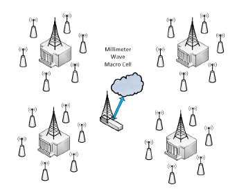 Figure 1: Millimeter wave Macrocell Backhaul
In a dense urban environment that demand load can change dynamically, [8]. In the latest industry projection for data usage requirements, the demographic shift of post-millennials shows that tablets are gaining in favor. Video phone calls are displacing texting and traditional voice calls especially in urban work environments. The current trends suggest that the majority connection will use a significant portion of the advertised 6Gb/s connections, [8]. Despite Multiple Input, Multiple Output (MIMO) radios covering the last connection in the microcell, the service to individual users is determined by the underlying switch topology under stress in high-density population centers and not the carrying capacity of the local radio modem, [9]. Additionally, the cost of a multi-tiered TCP/IP switch network in smaller area ultra-dense networks due to the propagation limits of the proposed RF bands implies that following the existing 4G aggregated network model becomes prohibitively expensive. [10], [11].
In this paper, the authors propose a dynamically reconfigurable network interface that allows bandwidth allocation to be resolved on the fly and shared equally with adjacently connected towers. The backhaul demand is accomplished through a virtualizable plane parallel optical topology that relies on the use of available fiber optic technology originally intended for long distance backhaul Internet applications. The proposed solution includes emerging flex-net transceivers located directly in the minicell sector 5G radios eliminating the need for expensive aggregated switches. The individual sectored wireless links gain direct access to the entire optical bandwidth of the backhaul network as required without upgrading micro cell towers. All of the microcell sector RF modems are serviced directly through a locally centrally managed sector scheduler node. This proposal includes a method for (SDN) software-defined network bandwidth allocation, use scheduling, and access control. Service scalability is handled through user-specified virtual networks connections that coexist with existing allocated fiber traffic. New connection and microcell commissioning can be achieved entirely without interference to existing network traffic flow or pathway allocations.
This paper introduces the concept of virtualizable ports or service interconnects by utilizing existing technology previously reserved for the highest speed terabit optical Internet backbone. The goal of this work is a presentation of a truly programmable SDN 5G solution. The result is a near flat network topology capable of accessing maximum available bandwidth on demand while maintaining system scalability. The embedded optical switch in the sector modem edge device is direct to fiber routing switch eliminating the need for a more traditional centralized layered network switch distribution approach.
2. Legacy Network Model
Typically in a switch based topology, increased access to bandwidth is limited by the availability of existing ports or pathways through the aggregated layered switches. In abnormal traffic situations breakdown occurs when the number of allocated switch ports exceed the expected number of users in a given sector. In the use case of a special event, such as a conference or sporting event where unusual traffic is concentrated in a smaller area, this requires the installation of additional switch devices installed specifically for the event along with increased numbers of temporary microcell sites. Additionally, connection delays in adjacent macrocell sectors are introduced as routing paths are arranged to handle the increased load. In ultra-dense networks, as expected the probability of achieving a successful connection to the user network decreases as the number of active nodes increase. Mitigating this effect requires dynamic allocation of bandwidth to the microcell. Responding to the increased demand during peak usage times is altered when unusual circumstances occur within the service area demographics.
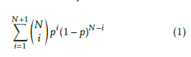
The switch fabric connecting the tower to adjacent towers and subsequently the backhaul Internet connection must exceed the expected number of active end-user nodes without interfering with existing service connections. The probability that more than one node (N+1) attempts to access the network port simultaneously is expressed in Equation 1the probability (p) of access success is directly affected by the number of users attempting to connect. Which naturally implies that increased activity will adversely affect available bandwidth as the number of endpoint nodes (users) increases. The backhaul bandwidth is further reduced as the shared bandwidth of each microcell connection is assigned. Additionally, adjacent sectors need reliable access to backhaul bandwidth to help take up the slack of the system and ensure timely hand-offs.
 In legacy network switch based systems, during expected normal use cases, the majority of the backup capacity resources allocated to a sector remain underutilized. The common base station design solution found in the majority of installations is to use additional routers and sector servers to increase the number of available sub-nets in the system. In low demand situations, these additional ports are fixed to the macrocell sector and are unused. These ports cannot be easily transferred to adjacent sectors or towers.
The underlying issue is that even with the use of millimeter backhaul the availability of routing ports in traditional network switches remains relatively static. New pathways to the centralized service center must be re-commissioned affecting the entire network. In most legacy systems prudent cost reductions require that only predicted network traffic load patterns are considered when designing the microcell distribution. If the base station is operating under stress, the result is an overall reduction in system performance. The solution lies in finding a methodology that both increases bandwidth and allows simple dynamic allocation and access to the increased bandwidth.
3. Edge Network Model
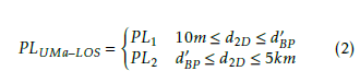
The most reliable 5G base station distribution model to date, which has been demonstrated in-situ, requires less than 1km between sector clusters. In most cases, urban models for high population centers suggest a 200-meter cell spacing. [3], [4]. The propagation models used in this proposal follow the (ETSI) European Standards Organization study [4] for an urban propagation model demonstrated in Equation 2 which models high density urban wireless networks. Highly dense urban models suffer from dense user traffic, propagation blocking obstacles, and multiple overlapping microcells. The maximum expected intra-base station spacing lies within the proposed 5km macrocell placement limit [4]. This limit also falls well below the threshold for significant optical dispersion interference between the closely packed optical channels required within the photonic switches. This suggested 5km limit also eliminates the need for optical amplifiers or repeaters between the microcells and the optical macrocell. Microcells are projected for 500m spacing however the ultra dense urban environment may make 200m more likely. The proposed networking topology model and router definitions used in this study reflect this limitation.
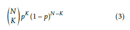
 The test model follows the ITU specification [12], for channel allocation. The number of occupied channels in the fiber connection between stations contains a finite number of substreams covering N sector nodes in the system. This implies that there is a probability p that K active nodes are accessing the network at any given instance. In high traffic demand areas, this load changes dynamically and is expressed in Equation 3.
 Consider that the majority of network traffic lies in simple data transfers such as email and web browsing requests, or similar nonstreaming operations. The emerging 5G network proposals offer much higher data rates to provide more advanced services. These services have near real-time prioritized packets, such as (VOIP) voice over IP and video streaming. In these use cases, the network path must stable to allow a steady non-blocking stream regardless of sector load. In most cases, the system designer builds the edge server to a predicted load model with approximately 20% overhead to handle additional network demands. Over-designing a sector results in increased power consumption, installation and maintenance costs for a given cell tower.
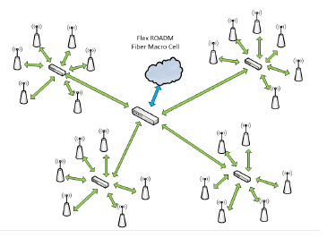 Figure 2: Flex Fiber ROADM Switched Backhaul Macrocell
Edge networking is a method that moves the control and access to the network directly to the end user node, at the edge. The optical network model proposed moves network access to the point of use. In traditional networks, multiple paths to a macrocell require fixed switch port allocations. In contrast, using the extreme bandwidth afforded by tunable laser transceivers and multiple wavelength selectable photonics switches allows the system manager to dynamically allocate bandwidth to meet the needs of the base station. When load demand increases, unused bandwidth can be allocated dynamically, without changing or adding existing equipment. Pathways to the Wide Area Network (WAN), are replaced with user selectable optical wavelength channels virtualizing port connections within the network. The photonic user reconfigurable switch embedded in each NIC allows all microcells to be interconnected and any backhaul pathway on demand, as in Figure 2 using the proposed solution model.
In the proposed solution the edge network wireless interface and the available capacity of the sector radio modem are finite and represents the only limitation to the system architecture. Predicting 5G deployment is difficult, the base station location remains static, while the connection load and bandwidth demand are intrinsically dynamic. In switch based topologies, priority signals with high data rate connections experience interference with the routing requirements of new connection requests. The radio hand-off and other management traffic requirements use much smaller packets in the transport model and can be handled in a secondary network designated for command and control. In edge networking, parallel network pathways are common to alleviate traffic congestion. An increase in the number of users and therefore required connections sharing backhaul access pathways cut into available port bandwidth, even for simple management tasks. The result is an increase in asynchronous packet collisions on the central network access ports that are simultaneously attempting to stream high-speed data and handle the dynamically changing handoff management packets. The wide-ranging user access data rates necessary to provide efficient, reliable 5G level service requires a new methodology. Bandwidth allocation for the requested service and the number of network connections need to be either commissioned or placed back in the service pool on the fly without interfering with ongoing network traffic.
4. Plane Parallel Optical Network Topology
The concept of a “plane parallel” network is based on open and free connectivity between all attached nodes within a computer cluster topology. This concept can be easily adapted to data delivery services found in cell tower networks. The optical network topology further introduces the concept of virtualizable interconnects or ports made up of assigned combined optical and temporal data streams. This access flexibility enables the system administrator to create connections or ports on demand within the available optical bandwidth, which on a single fiber is currently in excess of 14Tb/s [13]. The underlying concept is to separate the optical wavelengths into service channels to parallelize the number of active networks within the system. Current research involves methods for managing highspeed data streams in optical systems. However, these methods are more of an adaptation of existing switch technology involving aggregated lower tiered switch networks. Once an optical pathway is set it remains relatively static to service the Internet backbone pathway, [14], [15].
The proposed optical backhaul uses extreme bandwidth networking interfaces to create a plane parallel network topology that allows multiple networks to reside on the same backbone without interference with adjacent traffic and increased delays. The proposed solution allows the sector control system to quickly establish and bring up additional sub-networks and assign service temporal data streams as required. The newly assigned virtualized interconnections allow system administrators to handle increased data loads and temporary high throughput services within the plane parallel topology. All access is direct to the optical network without reassigning existing pathways or switching through other physical ports as within a tiered switch system. Redundancy and resiliency are provided through access to multiple fibers. Optical networks have direct scalability intrinsic to this methodology through the use of redundant fiber bundles.
Networks and sub-clusters can be commissioned and decommissioned on the fly as opposed to required downtime through manipulation of the physical switch port and cable swaps between the installed macrocells. The basis for this plane parallel system is the use of photonic (ROADM) Re-configurable Optical Add Drop Multiplexer optical switch device and wavelength tunable transceiver lasers. These photonic interfaces are embedded directly within each network interface controller (NIC) located at the microcell sector interface. The central traffic management software can program any ROADM device to switch any frequency to a specific fiber. Using the ITU channel specification, the single fiber can handle 72 200Gb/s wavelengths simultaneously. The ROADM device allows one or more of these wavelengths to pass through reducing unnecessary traffic at the end node. A single fiber can easily handle multiple macro cells at the proposed full capacity of the 5G microcells. Legacy protocols are all supported through a required new socket layer control interface that can encapsulate existing protocols delivered to the NIC. Pre-assigned management and service data streams are located on separate wavelength networks within the optical interface. Service requests are handled as a task-oriented or process assignment which allows individual control of both the node service commissions and separation of parallel sub-networks providing requested services.
The centralized system scheduler-management application utilizes a common management network to respond to service requests from sector modems. Since all nodes are simultaneously available on the parallel fiber interface, a method is provided to handle handoff and assignment to active data streams that utilize a process ID addressing scheme rather than the common physical address used in existing network protocols. Service to the user is assigned a process ID, in email text legacy phone services these packets transmitted in the backhaul with the process or service connection ID and the IP addressing is decoded at the sector micro cell interface. If multiple users are streaming video this process ID can be parallelized to send the live video, or conference meeting stream to multiple users without establishing separate connections.
4.1. Optical Network Topology
The proposed network takes advantage of the extreme bandwidth availability using existing optical network interface equipment. A closed loop testbed was built to verify simulation models for both physical transmission of highly dense optical signals and the proposed transceiver modem used in the proposed NIC. Since this application is intended for use in a large scale distributed edge computing environment, one that can contain more than 10K connected nodes or devices, it is assumed that the maximum distance between any node is within a 1 km boundary to avoid dispersion effects found in long haul optical networks. In this configuration, any of the issues associated with optical dispersion and ICI (inter-channel interference) have negligible effects within this application.
The outstanding challenge involved with 5G backhaul bandwidth allocation is handling the dynamic increase in high-speed streaming services combined with the relatively short distance between handoff nodes. The number of users and the type of service requested is dynamically changing. It would be a waste of the proposed system’s available bandwidth to simply assign optical channels of equal capacity to each microcell sector. The handoff from one radio to another is as simple as enabling an otherwise blocked temporal substream in the new radio already present on the optical interface, verifying the connection and dropping or blocking the stream on the previous radio. The proposed solution simulation example utilizes 50Gb/s tunable transceivers although 10Gb/s work just as well. The ROADM optical switches are embedded in each network interface card to allow a contention-less, colorless and bidirectional connection directly to one or more backbone fibers making up the plane parallel network distribution. Ideally, scalability of services requires adding fiber transceivers to the NIC interfaces in the microcell node using one or more of the dark fibers in the macrocell bundle. Telecom fiber installations typically include 12 to 24 fiber pairs for future use.
4.2. Flex Grid at the Edge
The use of ROADM based photonic switches flexible grid capability does not limit nor relegate the available channel spacing to one fixed size, rather the scheduler-manager application can assign varied channels boundaries within available requested optical range as needed to fill the optical boundaries. See Figure 3, which illustrates the flexible distribution of optical channels allocated. The impact of this optical boundary flexibility is that existing optical backhaul networks with fixed optical bandwidth boundaries can easily coexist with the addition of flexible channel allocation. Temporary ad-hoc networks commissioned for short term use can be combined into a larger channel if needed by a macrocell. Higher capacity channels can be assigned in a specific sector during peak usage hours and reassigned as the demand changes throughout the system.
The entire proposed network topology shares one or more common bidirectional fibers linking the sector modem at the edge thus bypassing the traditional distributed layered switch topology found in most 4G and legacy networks. The proposed method achieves a high-end user count with a flexible ratio of streaming (large packets) to service and management (small packet) distribution. Secondary transport methods evaluated varied between more common TCP/IP, and RDMA (Remote Direct Memory Access) favored by streaming clients. RDMA has significantly lower response latency because it systematically bypasses the processor core software by using the transport layer stack writing to memory directly. RDMA has an advantage in streaming services because large data files can be downloaded directly to the macrocell buffer to be distributed at a lower rate, freeing up the bandwidth to service other requests.
Proposed 5G market strategies favor streaming applications, and therefore the proposed solution will focus on the challenges of higher speed data and streaming packets. The optical router to radio interface will assume a 40Gb/s – 50Gb/s Ethernet connection assigned to one or more optical channels on a single fiber. The simulation of the control system assumes a minimum of four separate fibers available to each macrocell microcell cluster. Integrated multiplexing photonic switches allow for any four fibers to any four fibers multiplexing switch at the edge, controlled electronically by the sector node. The backhaul access can easily be scaled up to a 16-by-16 switch in future deployments. Similar networks have been proposed in HPC (high-performance computing) platforms [16, 13].
The embedded optical switch proposed allows the system to select one or more optical fiber pathways to adjacent towers or directly to the centralized backhaul Internet connection or data telecommunication center. Handoff communications are handled by the local towers rather than a centralized data center.
4.2.1. Available Optical Bandwidth Potential
The ROADM devices coupled with wavelength tunable lasers offer a ”flexible” wavelength grid mapping capability that is completely user programmable. Acknowledging that this system proposed must exist in legacy networks, we will follow the ITU 694 wavelength channel assignment grid [12]. The ITU G694 specification currently has a defined maximum channel capacity of 100 GHz bandwidth each within the L band (1500 nm), made up of 72 optical channels of 100 GHz each from 190 THz to 194 THz [12]. Each 100 GHz channel has a standard capacity of 200 Gb/s each, using the common PAM (pulse amplitude modulation) 2 bit per Hz method. The data rates used in this study reflect this to illustrate the system viability using lower density modulation techniques. Emerging transceivers are demonstrating QAM 16, QAM 64 and OFDM over fiber, [13]. The term ”flex grid” suggests that each available optical channel can be broken up into sub-channels as long as the highest density channel boundaries remain static. Sub-optical channels are chosen such that the entire boundary is filled leaving no unused assigned space. A simple example is that of a single 100 GHz channel. The highest bandwidth under ITU, which can be subdivided into any combination equal to 100 GHz. Example, a single 50GHz channel, a single 25 GHz channel and the remaining can be a second 25 GHz channel or two 12.5 GHz channels as needed. The scheduler manager makes this allocation based on the type of service (data rate) and the number of expected users (nodes) on the microcell sector radio. The ROADM device is programmable electro-optically allowing these boundaries to be assigned. The optical wavelength and bandwidth representing the allocated sub-network channel to pass either upstream or downstream along the fiber. Figure 3, illustrates the existing boundaries within the ITU grid [12], and the flexible boundary assignments within each ROADM switch NIC device. It is important to note that ROADM devices have been demonstrated operating outside of the ITU assigned channel grid constraints and can have a completely user programmable boundary for channel allocation, [17]. In the test bed for legacy network compatibility the ITU grid boundary definitions are used.
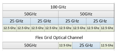 Figure 3: Single channel 100 GHz band divisions
Optical-Temporal data distribution is a method where the optical channels exist in a parallel plane. Each subsequent optical channel is broken up into temporal streams to accommodate varying bandwidth requirements filling otherwise empty space. The proposed solution provides that each assigned optical channel has the ability to further allocate the available bandwidth with a subset of temporal data-streams. Since most individual user connections cannot fully utilize 200 GB/s and promised 5G service is no more than 5 GB/s, the wide optical bands are filled with multiple data streams separated by time. A TDMA based set of temporal sub-data streams are included in the proposed solution shown in Figure 4. This hybrid optical channel/temporal data stream method allows the management controller to fully utilize the extreme bandwidth of the fiber, without using de-aggregation fixed port network switches. This arrangement is desired because the bulk of the connections will be asynchronous and flexible in size. Connection assignments are made using a single data stream or can be combined into compound streams when higher throughput is required by the service requested.
| Optical
Bandwidth 100 GHz 50 GHz 25 GHz 12.5 Ghz |
Modulation
Density 200 Gb/s 100 Gb/s 50Gb/s 25 G/s |
Channels
Available 72 144 288 576 |
TDMA
Streams 2304 4068 9216 18432 |
Stream Bit Rate
6.25 Gb/s 3.125 Gb/s 1.56 Gb/s 781 Mb/s |
Table 1: Single fiber sub-channel data capacity
Once a connection has established the wavelength and temporal stream assigned to the connection are given a unique connection ID code used as a compact routing header. The resulting connection assignment serves as a virtual port and is defined as a specific optical channel with one or more temporal data stream. The routing pathway is therefore further defined as Fiber 1…n, ITU channel wavelength 1…n, and temporal data stream 1 + n + m. One or more end user can share a single optical channel and temporal stream using the assigned connection ID code in the proposed socket header as a delivery method.
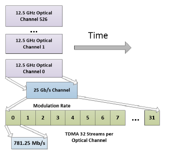 Figure 4: Parallel Optical Temporal Streams
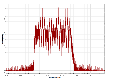 Figure 5: Parallel Optical Wavelengts
The sub-data streams are assigned by the scheduler-manager software when a connection is commissioned for a specific service or process. A channel request packet is sent to the scheduler manager node for increasing or relinquishing assigned bandwidth back to a common resource allocation pool. The number of temporal sub-streams assigned is entirely up to the schedule manager. In the example application, each ITU designated optical channel has been assigned 32 temporal data slots within each optical transport band. A single base station can supply 9,216 1.56 GB/s data streams using a 50 Gb/s laser transceiver on a single fiber. Individual connection capacity is calculated using existing radios modulation capability coupled with the assigned bandwidth of the optical channel. In the test bed, example channel capacity is limited to a simple optical PAM modulation signal and using existing ITU defined channel boundaries. Simulation indicates that the multiple wavelengths can easily coexist at these channel boundaries. Figure 5, shows a simulation of 16 ITU sub channels all using 40 Gb/s lasers over a single 1 km fiber. A breakdown of an available channel using the suggested 32 sub-temporal data slots is shown in Table 1. This table contains the channel capacity for each of the assigned optical bands and temporal sub-channel count and the number of supported streams and capacity of each. A single fiber with 72 100 GHz optical channels can contain up to 14.4 TB/s capacity using this method. The backhaul quad fiber integrated edge switch has a capacity for 57.6 Tb/s.
The proposed photonic NIC contains packet buffers in the physical layer with intrinsic transceiver buffer load and unload times dependent on buffer size and memory access speed. The use of temporal data slots allows the system to synchronize the projected arrival time of the next data slot to match the physical load time of the buffers used. In most cases using temporal sub-channels allows for data buffers to be loaded or unloaded while waiting for the next available data slot, thus limiting transmission gaps within the optical channel.
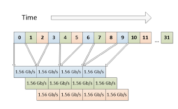 Figure 6: Aggregated staggered Temporal Data Stream
The chart in Figure 6 shows a typical scheduler assignment that uses four lower rate temporal data streams of 1.56 Gb/s each to be combined as a single 6.25 Gb/s virtualized port. In this example, the assigned multiple temporal slots are staggered to match the buffer fill times. The result is an effective zero buffer wait state for the physical transceiver buffers. In high bandwidth transmission non-aggregated packets that make up the bulk of networking traffic leave behind large gaps in the available transmit times. The temporarily assigned optical channel and sub-data stream act as virtualized connections at the socket layer. In the proposed network a commissioned modem tunes the laser and the ROADM receiver filter to a specific optical frequency and the electronics receiver uses the frame-sync timing signal from the command and control stream to synchronize the radio transceiver. The majority of packet buffering is handled directly at the edge as data is loaded into the physical layer buffer of the 5G radio modem.
4.2.2. Switch Scalability Model
The proposed 5G 5Gb/s use case can be realized using this distributed aggregation model using an optical transceiver with 25 Gb/s capacity shared across 32 temporal substreams. This transport data rate closely matches the proposed 5G maximum data rate and fits within the existing boundary of the existing ITU grid. As an example, in a single fiber network, consisting of eight sector 5G radio modems this represents nonblocking capacity for over 2000 individual 6 Gb/s data streams on a single fiber. A quad fiber ROADM switch increases this capacity per base station to 8000 noninterfering streams. Assuming the average expected end-user node typically requires around 1 Gb/s the number of available connections can be increased to 32K. The entire network capacity shares the plane parallel bandwidth assignment boundaries and an updated boundary map is distributed as a management packet on the control network. This allows all connected macrocells and microcells to know where a service stream is located within the optical/temporal channel assignment. Consider a 5G urban network with 6 Gb/s service capability and a projected average of 200 active connections at any one time per macrocell spaced at 1km. Using a shared fiber backbone connection 40 microcells spaced a maximum distance of 200 m from the macrocell can be serviced using only four shared fibers. The quad-optical switch proposed allows any sector radios access to the four backhaul fibers. The central scheduler manager handles the subnetwork assignments from the resource pool. When a connection is dropped, the channel allocation is demapped and returned to the resource pool. All connection requests use the single command and control optical network.
In this macrocell configuration, each of the four backbone fibers has a full spectrum carrying capacity of 14.5 Tb/s based on the ITU 100 GHz grid model. A single 16 sector microcell utilizing a quad fiber has direct access to 57.6 Tb/s of backhaul bandwidth. This translates to 9216 connection single temporal data streams each carrying 6.25 Gb/s covering the basic 6 Gb/s desired service with overhead for control messaging, from table 1. If 20 Gb/s connections are required, there are two compromise solutions using the standard ITU grid. Three temporal data streams can be combined for 18.75 Gb/s on 3072 virtualized connections or four data streams can be combined for 2304 25Gb/s connections. The user programmable flexibility of the optical and temporal data assignments suggests that any combination up to the optical switch’s maximum capacity for an assigned channel can be commissioned on the fly. The bandwidth allocation and connection commissioning are handled by the central scheduler manager node as required. Channel and sub-net assignments are negotiated by the requesting node for the type of service desired without impacting the other ongoing connections.
4.2.3. Test bed model
A testbed modem was used for the study using a twochannel transceiver with a functioning block diagram as shown in Figure 7 . The test bed consists of two (SPF+), Small Form-factor Pluggable, 10 G Tunable Lasers, and a pair of ROADM photonics devices. The testbed was used to verify that two adjacent dense packed optical channels can co-exist using a commercially available ROADM device [18], on the same fiber.
Measurements were made with adjacent lasers at full data rates and through separate photonics filters assigned before transmission. Inter-channel interference was measured on adjacent channels using a 20GS/s oscilloscope and found to be well below 100db specified by the ITU grid flex switch manufacturer, captured in Figure 8. Individual grid assigned optical wavelength channels can be duplicated as long as they are not located on the same fiber.
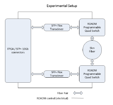 Figure 7: Experiment Schematic
Consider an extremely large control system, one defined as having more than 10K device connections. Distributive control is easily realized using this proposed topology. Lower bandwidth connections such as voice traffic, email or Internet browsing are assigned much smaller subdivided optical-temporal data streams. In most applications, these assigned data streams contain more capacity within the sub-channels then their existing counterpart high bandwidth switch based ports.
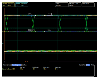 Figure 8: 10G received eye pattern with less than 100 db SNR
Advanced modulation techniques can increase the bandwidth of existing ITU channels or a custom optical channel distribution can be used in a homogeneous configuration. Specifically, one that does not have to conform to any industry-wide standards for channel spacing and center frequencies, such as a singularly connected private network. A recently demonstrated 400 Gb/s 64 QAM modulator [19], could increase the number of available 5 Gb/s links for a base station with a single fiber to just over 4500 service sub-nets, with a 500m separation limit. The bit rate limitation is due to the optical distortion effects common in higher order modulation methods.
4.2.4. Dynamic Port Assignments
A control access channel connection is maintained such that all available resources and radios can request service from the scheduler manager from a shared local network management channel. This same control path is shared by adjacent towers to facilitate handing off sub-nets instructing the new radio to switch the optical signal to the new sector. The process of bandwidth allocation and commissioning of system resources is independent of ongoing connections. In most applications, one or more optical-temporal streams are assigned as default command and control pathways for the desired service. The only one universally available command access network is permanently assigned to all macrocells and microcell NIC cards to facilitate a fallback command and management network path. During registration and commissioning the original transceiver MAC (media access controller) address, specific to the physical NIC in the sector radio, is used to identify the requesting device. Once commissioned all data transfers are sent with the process connection node ID code assigned during commissioning. The highest physical layer of the optical modem selects the optical channel and captures the assigned temporal streams and checks each transfer with the process ID, to repackage and route the data to the end user. The control management system can directly access any assigned device by using the commissioned user node ID registered in the resource pool data base. During task and process communications, all network traffic after this uses the assigned optical temporal data paths and connection ID codes to distribute packets to their intended recipients.
4.2.5. Simulation Results
Performance of the proposed topology is limited to the latency in the photonics switching and modulation technique used. There are no multi-tier network switch buffers to fill, as are found in non-blocking switches. There is however a delay exists when an edge NIC is waiting for the next periodic arrival of the assigned temporal data stream.
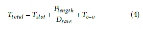
During commissioning, the scheduler Manager uses the database of resources coupled with the requested data rate to match the temporal streams to the service NIC buffer fill and flush times. This temporal assignment mitigates extraneous delays and creates a near zero wait state delivery schedule. The total latency is defined by the stream availability delay and the electronic to optical conversion delay and modeled in Equation 4. Where total latency is the slot arrival time Tslot, added the data transfer propagation delay,
Plength
Drate and finally electro-optical delay transforming the electronic signal to optical Te−o. In the hybrid optical edge switch, there is no tiered switch induced latency. Ideally, the arrival time of the next available temporal data stream should match the time to fill the transceiver buffer. This method hands-off large stream buffering to the microcell sector radio rather than the shared network switching topology.
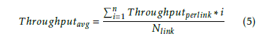
 Throughput is dependent on a number of active links and their respectively assigned optical bandwidths. It is therefore defined by the average of the sum of the through-puts of all the subchannel links Nlink as in Equation 5, where Te−o represents the electronic to optical conversion delay.
 In this study, the single pathway latency for a delivered packet was both simulated and measured in the test bed to determine the average delivery latency. The size of the packet used was a range of test packet sizes from 16 bytes (management request or acknowledge) and large scale streaming 16K packets and found to center around 4 uS in the 40Gb transceiver, and 3.5 uS in the 50Gb/s Ethernet over Infiniband transceiver as shown in Figure 9. The simulation used NS-3 with a custom model generated using the measured latency from the testbed, There is a slight increase in latency as the packet size is maximized due to the last point buffer fill times piling up during transmission. In most cases the entire receive buffer is available long before the next packet arrives when simulating a 6 Gb/s 5G user link.
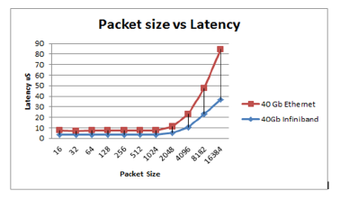 Figure 9: Transport latency vs. packet size
As the network load approached the maximum throughput of the assigned channels, the latency increased, primarily due to occasional loss of synchronization with the assigned data stream. This can be remedied by either increasing the staggered delay assigned slot or the size of the fill buffer in the transmitter-receiver interface. The lower network loads from 1 to 85% capacity remain reasonably static as shown in Figure 10. The temporal data streams are continuous, so it follows that the increase in latency at the higher packet sizes is due to the encapsulating of the segmented packets within the new socket structure. This effect was caused by the legacy TCP/IP protocols, including Ethernet ARP (address resolution protocol) included within the network stack. The optical transport header making up the outside layer using the process ID code to identify the packet at the destination, replacing the physical addressing used in the legacy protocols. Jumbo frames were not used in the study, so the limitation of 1500 bytes [20], remained requiring the transmission of several smaller packets when larger block sizes where transmitted.
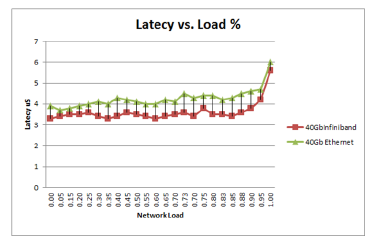 Figure 10: Transport latency vs. network load
5. Conclusion
The purpose of this study was to explore an alternative approach to the issue of bandwidth availability in 5G macrocells. The proposed approach was to use emerging technology for terabit networking and apply it as a (FTTC) fiber to the curb solution. There are three key issues addressed.
- Reconfiguration of the bandwidth to match dynamic loads.
- Reduce system costs while providing scalability.
- Provide a method for de-aggreagating 200 Gb/s streams directly to 6Gb/s streams without tiered switch network.
Simulations followed by testbed experiments show that the emerging ROADM photonics technology can be adapted to allow the network designer to provide a complete software-defined distribution network that is dynamically reconfigurable on the fly. The existing commercial hardware meets this constraint. Direct optical access requires replacing the Ethernet physical layer in the TCP/IP stack with a new layer that provides a bridge between the terabit optical interface and the 5G microcell sector modem 10G Ethernet NIC. Scalability requires a swap out of the SFP photonics transceiver device in the NIC to 40Gb/s model to support the expected 20Gb/s 5G service model. A prototype interface was tested and acted as a proof of concept for this work, which met the requirements of the 6Gb/s service model using a ROADM module [18] and an SFP+ 10 Gb transceiver through 500m of fiber. Certainly, within the confines of existing legacy optical network standards [12], it has been shown that it is possible to provide adequate 6Gb/s data streams co-existing on a single fiber without blocking or interference with legacy 4G and 3G traffic. Additional efforts are needed to fully refine and test a new physical (SDN) software-defined networking protocol layer to be applied to a fully expanded testbed that models an entire 5G macrocell. Future efforts will focus on the command and management protocol necessary for full deployment of this concept.
- T.S. Rappaport, S. Hu, R. Mayzus et al.,Millimeter Wave Mobile Communications for 5G Cellular. It will Work, IEEE Access Vol1, pp 335-349, May 2013.
- N. Bitar, SDN and potential applicability to access net- works, in Optical Fiber Communication Conf. and Exhibition OFC 2014, paper Th1G.4.piling
- M. Coldry, J-E Berg, L. Manholm, C. Larsson, J. Hasryd, Non Line of Sight small cell backhauling sing microwave technology, IEEE Wireless Commun. Mag , Vol 51 No. 9, pp. 78-84, 2013.
- ETSI. New ETSI Group on MillimetreWave Transmission Starts Work. Technical report.
- C. Dehos, J.L. Gonzales. A. D. Dmoenico, D. Ktennas L.Dussopt, Millimeter Wave Access and Backhauling: The solution to the Exponential Data Traffic Increase in 5G Mobile Communications Systems, IEEE Trans Wireless Commun. Mag , Vol 52 No. 9, pp. 88-95, Sep 2014.
- X. Ge, S. Tu, G. Mao, C.X.Wang, T. Han,5G Ultra-Dense Cellular Networks, IEEE Wireless Communications, 2016.
- S. Hur, T. Kim, D.J. Love, J.V. Krogmeier, T.A. Thomas, A. Ghosh, Millimeter Wave Access and Beamforming for Wireless Backhaul and Access in Small Cellular Networks, IEEE Trans Wireless Communications, Vol 61 No. 10, pp. 4391-4403, Oct 2013.
- CISCO. Global Visual Networking Index: Globile mobile data traffic report forcast update, 2015-2020 (2015) White Paper
- S.F. Yumas, M. Valkama, J. Niemela, ,Spectral and Energy Efficiency of Ultra Dense Networks under Different Deploymenmt Strategies, IEEE Commun. Mag , Vol 53 No. 1, pp. 90-100, 2015.
- Intel Case study: Rethinking small cell business model(2012), Intel White paper
- J. Robson. Small cell backhaul: an analysis of small cell backhaul requirements and comparison of solution, Cambridge Broadband Networks Limited(2012) White Paper
- International Telecommunications Union Spectral grids for WDM applications: DWDM frequency grid, REC G.694.1 201202 I 2012
- N. Terzenidis, P. Maniotis, and N. Pleros, Bringing OptoBoards to HPC- scale environments: An OptoHPC simulation engine, in Proc. 1st Int. Workshop Adv. Interconnect Solutions Technol. Emerging Comput. Syst., 2016, Art. no. 6.
- X. Li, K. Kanonakis, N. Cvijetic, A. Tanaka, C. Qiao, and T. Wang, Joint bandwidth provisioning and cache management for video distribution in software-defined passive optical networks, in Optical Fiber Communication Conf. and Exhibition (OFC), San Francisco, CA, Mar. 2014, paper Tu3F.5.
- V. Lpez, O. Gonzlez de Dios, L. M. Contreras, J. Foster, H. Silva, L. Blair, J. Marsella, T. Szyrkowiec, A. Autenrieth, C. Liou, A. Sasdasivarao, S. Syed, J. Sun, B. Rao, F. Zhang, and J. P. Fernndez-Palacios, Demonstration of SDN orches- tration in optical multi-vendor scenarios, in Optical Fiber Communication Conf. and Exhibition (OFC), Los Angeles, CA, 2015.
- Y. Matsuoka et al. 20-Gb/s/ch high-speed low-power 1-Tb/s multilayer optical printed circuit board with lens-integrated optical devices and CMOS IC, IEEE Photon. Technol. Lett., vol. 23, no. 18, pp. 13521354, Sep. 2011.
- Infinera The Next Generation of Coherent Optical, Advance Coherent toolkit for Super Channels (2016), Infinera White paper
- SANTEC 4 Channel Mux / Demux Module MDM-15 (2018), SANTEC data sheet
- G. Wei-Lu T. Sakamoto, T. Kawanishi, Flexible high order QAM transmitter using tandem IQ modulators for generating 16/32/36/64-QAM with balanced complexity in electronics and optics, OSA Optics express Vol 21, No 5, pp. 6213-6223 Nov 2013.
- M. Mathis, J. Semke, J. Mahdavi, T Ott The Macroscopic Behavior of the TCP Congestion Avoidance Algorithm CCR ACM SIGCOM (1997) vol 27 No. 3 ISSN 0146-4833