Acquiring Energy from the Harmful Radiation Emitted by Compact Fluorescent Lamps

Adv. Sci. Technol. Eng. Syst. J. 4(2), 314–318 (2019);
 DOI: 10.25046/aj040240
The purpose of this work is to present new technology in acquiring energy from the compact fluorescent lamp (CFL) and store it in a super-capacitor to operate the emergency exit lights. Many studies show energy-efficient light bulbs may emit harmful radiation. This type of lamp emits high levels of radiation, causing migraine headaches, fatigue, and other health problems. The proposed system is based on the magnetic near-field coupling between the flat wound induction coil and the compact fluorescent lamp. CFL bulbs emit excessive dirty energy, the most of this energy will energize the super-capacitor and then in emergency lighting batteries through DC/DC step-up converter. So the proposed electronic device show a new technology to harvest the radiation generated by the bulb and charging batteries and secondly reduce the electromagnetic radiation inside a home, offices, and protect our children from radiation. The primary objective of the device is to reduce electromagnetic pollution at home and offices and re-generate energy from harmful radiation. The results are satisfactory and advantages of using technology to recycle electromagnet radiation to charge a battery, use at a critical time like an emergency light system. Besides, we can use it for many other applications. This purpose of this working is an extension of work initially presented in 2017 Ninth International Conference on Advanced Computational Intelligence (ICACI).
1. Introduction
Many studies from world health organization approve that the compact fluorescent light bulb (CFL) produce electromagnetic pollution. These unsafe radiate products directly from light and distributed in all our bedroom, meeting room, and offices [1,2,3,4] the nearer your seat to the bulbs the greater your electromagnetic exposure. The electromagnetic radiation generated is not the same amount of energy, as the bulb power increases the radiation increases too, as shown in Figure 1. The research paper has focused on how much power can acquire from this harmful radiation. Electromagnetic radiation energy harvesting represents a promising solution in charging the super-capacitor from free energy around us, and we start making electromagnetic pollution recycle system [5,6,7]. In this work, we focus on the possibility to reuse radiation for charging the battery of emergency exit lights. In particular, we propose to exploit a near-field magnet coupling to acquire maximum radiation. Experimental from 26 kHz to 28 kHz [8,9,10,11,12].
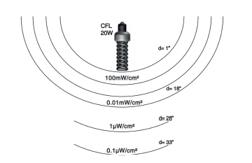 Figure 1: Shows that the field strength very high near the CFL lamp
The device consists of a flat wound planar coil (resonant inductive coupling), a voltage multiplier, a supercapacitor, and DC/DC adjustable step-up power to energize the emergency exit light, as shown in Figure 2. This research is organized as follows: in Section 2: We present the simulation and design of the flat planar coil. Section 3: Architecture of the proposed harvester Circuit. Section 4: Presents the results and verification. Finally, Section 5: Conclusions.
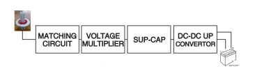 Figure 2: Block diagram of CFL energy harvesting device
2. Simulation and design of the flat planar coil
This present section shows the conceptions and characterization of planar inductor. The planar coil is mostly used in high-frequency applications and designed as tracks on solid support [13,14,15,16]. The proposed Coil shown in Figure 3, was optimized by evolving the form of the flat spiral coils. In this section, the design of the flat wound coil is described, and coil specifications for the effective permeability are introduced. The variables that parameterize the form of the coil are the wire thickness (t), inside diameter (d), outside diameter (D), number of turns (N), the average radius of the coil in inches (R) and width of the loop in inches (W). In the following section, the fabrication process is present in detail. Characteristic properties of the type of coil are high magnetic leakage and parasitic capacitance highly. This formula applies at low frequencies using copper wire.
Where:
L= Inductance of coil in Henry (H); W= width of winding area (cm); a= average radius (cm);
N= Number of winding ;
L=(21.5*N2*2*a)/(1+2.72*(W/2a))
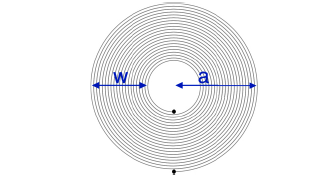 Figure 3: Flat wound planar induction coil
The actual fabrication process will make on plastic diameter approximately 90 mm. With the current mask design, one level contains only one coil, as shown in figure 4.
It is interesting to note that the Pout increases with the increase of the area diameter and the number of turns (N) of the planar coil. This will can be used to select an adequate output power. Since the device is an inductor, in practice, the resistance to the electromagnetic coil can be neglected compared to the reactance. The inside diameter of the flat coil must be the same as the CFL diameter with average tolerance. Thus, we can fix the CF light inside the induction coil, as shown in figure 5.
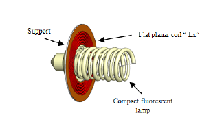 Figure 5: 3D design of the inductive coupling method
2.1. Analysis of a resonant coupled system
There are two ways to measure the H field in the axis direction of the planar induction coil and the radial direction of the coil; it can be seen in Figures 6 and 7, respectively.
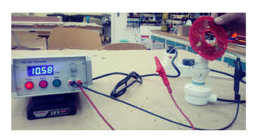 Figure 6: Magnetic field measurement in the axis direction of the flat coil
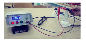 Figure 7: Magnetic field measurement in the radial direction of the flat coil
2.2. Validation of the resonant inductive coupling
The position of the planar coil is most important compared with the position of CFL and the quantity of energy and efficiency changes. The testing is done, and we conclude that when the planar coil at 90◦ to CFL the energy I maximum, it can be seen in Figure 8. It is encouraging to note that the radiation recovered from the CFL is higher and maximum when the axis of the planar induction coil is in the direction of the axis of the lamps at 90◦ (near filed coupling) as shown in figure 9. During the test phase, we will use the magnetic field in the direction of the axis of the coil in our measure of construction and testing.
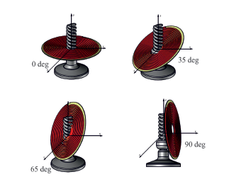 Figure 8: Testing different angles of resonant inductive coupling
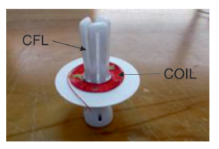 Figure 9: A real photograph of our test phase
After the construction phase of the flat wound planar induction coil coupled in the axis direction of the CFL (90◦), we will study the electronic circuit board which can convert the harmful radiation energy to DC power.
3. Architecture of the proposed circuit
The corresponding architecture of the proposed harvester circuit demonstrated in Figure 10. It consists of a resonant inductive coupling, supercapacitor and DC/DC step-up convector connected to the battery of the emergency exit lamp.
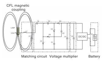 Figure 10: The schematic of a harvest and charging circuit
The components which are used to make harvesting circuit, as shown in the Table 1.
Table 1: Proposed harvester circuit components
| Components Name | Components Value |
| Harvesting Coil Lxl | 1 Henry |
| Diode D1,D2,D3,D4 | HSMS 2820 |
| Capacitor C1,C2,C3,C4 | 56 pF |
| Sup-Cap | 5.1V/400F |
| DC/DC converter | 5.1V/5.7V |
The resonator circuit consists of a flat induction coil is coupled with the compact fluorescent lamp (nearfield coupling). All reported measurements prove that electromagnetic radiation emissions from CF lamp have a peak at about 26.74 kHz, more precisely, the spectrum of the signal received in the case of coupling between the flat coil and the fluorescent lamp (20W) has been used as adjustable impedance matching circuit at 26.74 kHz [17]. The maximum amount of energy is extracted from the coil when the capacitor is a conjugate match to the source, as shown in Figure 11.
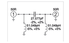 Figure 11: Matching network circuit
Voltage doubler rectify low Alternate Current (AC) collected from the resonator circuit to DC voltage [18,19,20,21,22,23]. It uses a series of capacitors and Schottky diodes to step up and rectify power concurrently. The energy is stored in a super-capacitor and energizing the battery of emergency exit lights. The picture below shows the final prototype used voltage multiplier with the output capacitor, as presented in the photograph 12.
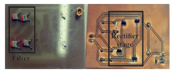 Figure 12: Picture of PCB rectifier circuit
4. Results and Verification
The hardware configuration of the CFL energy harvesting device is mainly on the inductive coupling method. The complete circuit diagram of the project can be divided into two different sections: Resonant inductive coupling, converter section (Rectifier). The flat receiver coil will have connected to a converter circuit through four stages. The first stage is a compensating network to maximize the induced current at the secondary stage by a matching circuit. The second part is a two-stage voltage doubler design with all the stage capacitors being the same value. The third stage is a super-capacitor for storing energy. The last step is A DC-to-DC power step up, as shown in Figure 13.
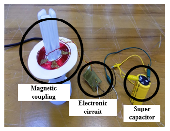 Figure 13: Previous project device
The DC voltage generated by the voltage multiplier will start charging the super-capacitor (5.1V /400F). The battery charging time depends on the range of storage capacity. Table 2 shows the necessary time to charge super-capacitor from CF lamp 20W.
Generally, charging time changes according to the storage capacity of Sup-cap. When the value of ability gets essential, the time of charging gets necessary too. The above table shows us that to charge a Supcap of 400F, we need a minimum of 15 days while the fluorescent is working 24h/24h, and a minimum of 5 days to charge a 400.0F Sup-cap. This phase demonstrated that the sup-cap is an excellent lowtemperature charger which is, so safe device to be used in our office and home-owners. There are many applications of the proposed idea such as: charging the battery of the emergency exit lights, smoke detector battery or alarm system. Finally, measurements of the DC power generated by coupling between harvesting circuit (Sup-Cap 5.1V /400F) with a 20W CF lamp as illustrated in Figure 14.
Table 2: Charging time for super capacitor with CFL (20W)
| Charging Time (Hour) | Charging a capacitor (Volts) |
| 0 | 0V |
| 1 | 0.3V |
| 10 | 0.8V |
| 24 | 1.35V |
| 48 | 1.89V |
| 72 | 3.45V |
| 360 | 5.05V |
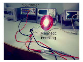 Figure 14: Conceptual view of radio-frequency (RF) energy harvesting
5. Conclusion
The concept of applying harvesting energy from the compact fluorescent lights application has been explored in this work. In this paper, we approved the announcement of the world health organization, that the compact fluorescent light bulbs are a popular choice for businesses and home looking for ways to reduce their electricity bills. High power density recovered when the planar coil in 90 degrees with the lamp. The coupling between the proposed harvester circuit and the CFL for energizing emergency exit light is presented and approved. The measured results of the spectrum of the power acquired by electromagnetic coupling. Only with one geometry type of lamp. In the next work, we will test more examples of light according to the geometry design.
- Masamitsu, Emily (May 2007). ”The Best Compact Fluorescent Light Bulbs: PM Lab Test”. Popular Mechanics. Archived from the original on April 26, 2007.
- S. Safari, M. Kazemi, H. Dehghan, H. A. Yousefi, and B. Mahaki, ”Evaluation of ultraviolet radiation emitted from compact fluorescent lamps,” Journal of Health System Research, vol. 9, no. 11, pp. 11771183, 2013.
- Abernathy. A, P. Cumbie,” Mercury accumulation by largemouth bass (Micropterus salmoides) in recently impounded reservoirs. Bull”, Environ. Contam. Toxicol. 17, pp. 595-602.
- Kane, Raymond; Sell, Heinz ,” Revolution in Lamps: A Chronicle of 50 Years of Progress (Second ed.)”. The Fairmont Press, Inc. pp. 189190. ISBN 978-0-88173-378-5, (2001). ”Philips Tornado Asian Compact Fluorescent”. Lamptech.co.uk. Retrieved 18 June 2013.
- Marks, A.M. Device for conversion of light power to electric power. U.S. Patent 4 445 050, 1984.
- Flaviu Pop, Clio Munteanu and Adina Rcan, ”The assessment of human exposure to radiated fields from different types of lighting”, International Conference on Modern Power Systems, pp. 6-9 June 2017.
- W.G. Fano, ”RF emissions of compact fluorescent lights”, Interference Technology, 2012.
- Flaviu Pop; Clin Munteanu; Adina Rcan and Silvan Pruu,” The assessment of human exposure to radiated fields from different types of lighting”, International Conference on Modern Power Systems (MPS), June 2017.
- Khodijah Mohamed; Hussain Shareef and Azah Mohamed, ‘’Analysis of harmonic emission from dimmable compact fluorescent lamps”, July 2011.
- Sam Aerts; Gnter Vermeeren; Carolina Calderon; Bla Vali; Matthias Van den Bossche and Leen Verloo, ‘’Exposure to electric and magnetic fields at intermediate frequencies of household appliances”, March 2017.
- E. coca, V. Popa, and G. Buta, ” compact fluorescent lamps l electromagnetic compatibility measurements and performance evaluation”,2011 IEEE EURO ,Portugal.pp.1-4.2011.
- P. kar, T. G. Palanivelu and B. Revathi, ‘’effective tests and measurements meclianisms or emi level identification in fluorescent lamp operation”, European Journal of Scientific Research, vol. 34, pp. 495-505, 2009.
- S. Bsan, S.Sahoo, R. Kumar and . K. Panda, ‘’Wireless energy transmission to piezoelectric component by flat spiral coil antenna-like structure”, IEEE International conference Sustainable Energy Technologies, Kandy, pp. 1-4, 2010.
- Kraus J. D., Fleisch D. A.: Electromagnetics with applications, Edition, McGraw-Hill, 1998.
- A. Rida, L.Yang and M.M. Tentzeris, RFID-enabled sensor design and application, Boston : Artech House, 2010.
- M.Kovama; N.Nago , R.Imai, M.shikida, H.Honda , M. Sato, ”Evaluation of Magnetic Beads Agitation Performance Operated by Multi-Layered Flat Coils”, International Solid-State Sensors, Actuators and Micro-systems Conference, pp. 2385- 2388, 2007.
- Myung-Eun Song; Yongke Yan; Sreenivasulu Gollapudi; Mirza Bichurin; Vladimir Petrov; Mohan Sangh, Design of Metglas/ polyvinylidene fluoride magnetoelectric laminates for energy harvesting from power cords, 2016 IEEE SENSORS, 30 Oct.-3 Nov. 2016.
- Gadalla, M .. M. Abdel-Rahman, and A. Shamim, ”Design. optimization and fabrication of a 28.3 THz nanorectenna for infrared detection and rectification11 , Scientific reports, 2014.
- Yang. X, Jiang. C, Elsherbeni, A.Z, Yang. F and Wang. Y, ”A novel compact printed rectenna for data communication systems”, IEEE Trans. Antennas Propag, pp. 2532-2539, 2013.
- A. I. Petrariu and V. Popa, ”The role of impedance matching for power transfer efficiency in HF RFID systems”, 2015 9th International Symposium on Advanced Topics in Electrical Engineering, Bucharest, pp. 386-391, 2015.
- Sasaki, Susumu, Tanaka, Koji, Maki, Ken-ichiro, ”Microwave Power Transmission Technologies for Solar Power Satellites”, Proceedings of the IEEE Vol. IO I, pp. 1438-1447, June 2013.
- Rault, Tifenn, Bouabdallah, Abdelmadjid, hallal, Yacine, ”Multi-hop wireless charging optimization in Low-Power Networks”, IEEE Global Communications Conference, 2013.
- Sellali. Mehdi; A. Betka ; S. Drid ; A. Djerdir ; M. Tiar ; S. Abdedaim, Implementation of new adaptive power-split management strategy in a battery-supercapacitor electric vehicle, International Conference on Electrical Sciences and Technologies in Maghreb (CISTEM), Oct. 2018.
No related articles were found.