An Innovative EPC Architecture based on Not Only Stack for beyond 5G Mobile Networks

Adv. Sci. Technol. Eng. Syst. J. 4(2), 319–332 (2019);
 DOI: 10.25046/aj040241
The traditional long-term evolved (LTE) network architecture faces major challenges due to the rapid development of mobile intelligent applications. Evolved packet core (EPC) network, as the core network of the LTE system, faces the same problem as well. In this paper, we propose an innovative EPC architecture, i.e., Not only stack (NOS)-EPC, in which we redesign the control paradigm based on the NOS framework. NOSEPC contains the user plane (U-plane), the control plane (C-plane), the management plane (M-plane), and the global network view (GNV). By using NOS framework, distributed control paradigm is turned into a centralized manner which simplifies the signaling flows, reducing the procedure latency and overheads. The operation of NOS-EPC is expounded by four main EMM procedures, including initial attachment, service request, handover, and detachment. Through comparison to LTE/EPC, and software-defined networking(SDN)-EPC, we elaborate the advantages of NOS-EPC on operating expense (OPEX), scalability, flexibility, signaling overheads, and user traffic transmission capability. The simulation results confirm that the proposed NOS-EPC takes advantages on the procedure latency and signalling overheads compared to the other EPC solutions, e.g., LTE/EPC and SDN-EPC.
1. Introduction
Current cellular network (i.e., LTE/EPC) is built as a hardware-based, closed, and inflexible architecture. It faces major challenges due to the rapid development of mobile intelligent applications. It is anticipated that the new generation cellular network, e.g., beyond 5G (B5G) network [1], achieves over 100 and 1000 times enhancement on the aspects of capacity and transmission rate. Advanced wireless techniques are developed to relieve the burdens on the air interface of the cellular network, e.g., massive multiple-inputmultiple-output (MIMO), non-orthogonal multiple access (NOMA). However, if we simply rely on these air interface-related techniques, severe challenges in B5G cannot be completely solved since various scenarios pose different requirements. For example, the ultrareliable low-latency communication (uRLLC) scenarios ers more about the massive volumes of connections. Thus, advanced network means and flexible network elements (NEs) design need to be applied to improve the system performance on the network level.
Considerable works have been done to improve the system performance. One of the most effective ways is the virtualization [2]. Several mainstream virtualization solutions have been proposed, such as network function virtualization (NFV), software-defined networking (SDN), cloud computing [3]. Among these solutions, NFV and SDN are promising approaches [4]. The NFV technique decouples the NEs from the underlay physical infrastructures. NE-special hardware is replaced with the commodity servers, which largely decreases the procure cost. Moreover, NEs could migrate among multiple commodity servers as software instances. Thus, operators could remotely schedule the resources according to dynamic workloads, decreasing the operational cost. SDN is another promising solution which separates the control plane and data plane. Most SDN-based architectures consist of a distributed data plane and a centralized control plane. The control functions in LTE/EPC are packaged as SDN applications. The SDN controller schedules the network resources in a centralized manner, which improves the programmability of the system.
However, SDN and NFV are originally intended for wired transmission networks. The direct integration of SDN and NFV into cellular networks lead to degeneration of performance improvement. There are several fundamental differences between the cellular network and conventional wired networks. First, in the cellular networks, NEs have more complicated functions compared to the wired network. The control functions include mobility management, traffic engineering, QoS guarantee, etc. The user functions include packet forwarding, integrity checking, etc. On the one hand, existing SDN protocols (e.g., OpenFlow) cannot deliver so many services. What’s more, a centralized SDN controller usually results in severe network congestion since it could not support so many services at the same time. Second, the protocol stacks in the cellular networks are tightly coupled. In the wired network, the routing table loosely decouples the routing function and data forwarding function. However, in the cellular network, it is difficult to decouple the control plane and user plane without changing the current protocol stacks. Additionally, each protocol entity in the cellular network maintains complex states (i.e. registered, idle, and connected) that involves a mass of signaling interactions, while the wired network works in a stateless manner.
Therefore, in order to improve the performance of virtualization techniques in the cellular network, it is necessary to redesign the control paradigms in LTE/EPC. In our previous work, we proposed an innovative EPC architecture based on the NOS, i.e., NOSEPC[5]. The NOS-EPC simplifies the signaling flows in LTE/EPC, reducing procedure latency and signaling overheads. In this paper, we conduct the research in a more comprehensive manner. The main contributions are summarized as follows:
- We propose an innovative EPC architecture based on NOS framework. We detail its evolution from a conventional LTE/EPC. The main components of NOS-EPC are elaborated.
- We use four main EMM procedures to illustrate how NOS-EPC works. The EMM procedures include initial attachment, service request, handover, and detachment. Additionally, we elaborate on how to incorporate new services in NOSEPC to address the flexibility of NOS-EPC.
- We show advantages of NOS-EPC through comparisons among LTE/EPC, SDN-EPC, and NOSEPC. We emphasize the features of NOS-EPC on operating expense (OPEX), scalability, flexibility, signaling overheads and user traffic transmission capability.
- We evaluate the performance of NOS-EPC through NS3 simulations. The simulations show that the proposed NOS-EPC could improve system performance significantly, compared to traditional LTE/EPC and SDN-EPC.
The rest of paper is organized as follows. In Section II, we review the current works on the architecture of the cellular network. In Sections III, we describe the structure of our proposed NOS-EPC. Section IV details how the NOS-EPC works, using four main EMM procedures. Then, in Section V, a comprehensive comparison between LTE/EPC, SDN-EPC, and the proposed NOSEPC is given. We conduct NS3 simulations in Section
VI, which evaluates the performance of the proposed NOS-EPC. We conclude the paper in Section VII.
2. Background and related works
The architecture of the cellular network is a hot topic in the past few decades. The current LTE/EPC could not satisfy the strict requirements of 5G and B5G [3]. Considerable efforts have been made to investigate the disadvantages of the current LTE/EPC system.
First, in the LTE system, NEs are built on the dedicated hardware, which raises CAPEX and OPEX. Second, NEs in LTE are highly integrated. In order to deliver a particular service, NEs needs to cooperate with each other which motivates unnecessary singling overheads. Moreover, highly-integrated NE design makes it hard to incorporate emerging applications. Third, diverse protocols are designed for different NEs. Heterogeneous protocols result in extra cost during traffic/signaling transmission.
In order to overcome above-mentioned challenges, some researches focus on the optimization of network architecture. Most works use virtualization techniques (e.g., NFV, SDN) to enhance network programmability. In these architectures, NEs are instantiated as packages on the SDN controllers or the software instances hosted on the VMs[6, 7, 8, 9]. The authors of [6] present an SDN-based architecture, named MobileFlow, to validate the feasibility of using SDN in the cellular network. [7] proposes a cloud-based architecture, i.e., CONCERT, which coordinates physical resources as virtual resources. The authors of [8] present an SDN-based 5G cellular system, i.e., SoftAir, in which a unified U/C-plane interface is designed based on OpenFlow. Another high-level cloudlet-based architecture is proposed in [9]. The authors address the seamlessness and low end-to-end latency between UEs and its Avatar.
EPC, as a part of the cellular system, has also been extensively studied [10, 11, 12, 13]. The authors of [10] propose a programmable mobile core network with an OpenFlow-enable data plane. The control function is implemented with an OpenFlow Controller that cooperates with MME. [11] presents a number of different options which are associated with the implementation of EPC over a cloud infrastructure and providing it “as a Service”. In [12], the authors detail an OpenFlowbased protocol to enhance network flexibility and programmability. A much more detailed analysis is given in [13], in which authors evaluate the network performance, considering five commonly used procedures.
Some other works conduct the optimization from the aspects of a particular service. [14] investigates an SDN/NFV-based platform in order to improve the performance of video broadcasting service. The improvement owes to the orchestrator in the core network, which is in charge of flow operations like replication and transcoding. [15] designs a 5G user plane function component (UPF) based on SDN to support network slicing, reducing the latency and improving the throughput. [16] focuses on PDN data transmission, in which the authors analyze the cost incurred by different virtualization schemes. In [17], the authors propose an SDN-enabled EPC to carry out inter-domains handover, which uses OpenFlow (OF)enabled switches as the main forwarding nodes.
It is noticed that the above-mentioned researches do not change the control patterns and interfaces in traditional LTE/EPC. The problems brought by the ossified protocol stack in LTE/EPC still exist. Thus, some researchers focus on the redesign of traditional paradigms in LTE. In [18], C-plane of RAN was reconstructed via data-signaling separation in the air interface. The control coverage and the data coverage are separately controlled according to the on-demand network. A virtualized RAN based on NOS is proposed in [19], which is aimed to optimize flexibility and sustainability. Meanwhile, signaling overheads and service response time are reduced.
The redesign of control paradigms in RAN motivates us to conduct similar methods to LTE/EPC. [20] only focuses on the reconstruction of S/P-GW in EPC. In this paper, we consider the whole region of the EPC/LTE network. We reconstruct the control paradigm based on NOS framework to decrease the signaling overheads and latency.
3. An innovative NOS-based EPC architecture for the mobile network
Unlike the mainstream virtualization techniques like SDN and NFV, the NOS focuses on the redesign of the paradigm of the cellular network [19]. It offers a mechanism that can help to build a virtualized cellular network architecture. In this architecture, network resources can be dynamically allocated and configured to improve the efficiency of utilization. Signaling interactions can be optimized to shorten the procedure duration and decrease the network overheads.
3.1 An Innovative EPC based on NOS framework
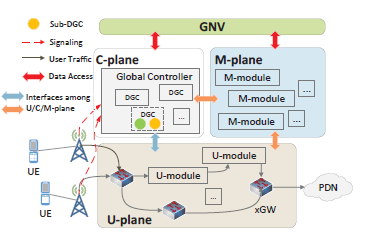 Figure 1: The architecture of the NOS-EPC
The essential methodology of NOS framework is breaking the boundary of protocol entities into different functions, and reconstructing the paradigm of the cellular network in the level of functions. The NOS framework decomposes the functions of NEs into the user plane (U-plane), the control plane (C-plane) and the management plane (M-plane). Data sources which are originally distributed among different NEs are now gathered into a logically centralized GNV. We redesign the network architecture by using NOS framework. The proposed NOS-based architecture is shown in Figure 1. It consists of U-plane, C-plane, M-plane, and GNV. The details of C/U/M plane and GNV are illustrated as followings.
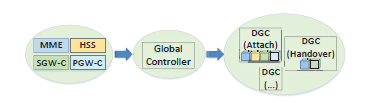 Figure 2: The generations of the DGCs
The U-plane is built in a distributed manner. In the U-plane, the user functions (i.e. GTP encapsulations, rules installations) of the service gateway (SGW) and PGW are merged into the xGW. U-plane modules (Umodules) for emerging services are introduced. Each U-modules is a processing element. The user traffic is routed among these U-modules under the control of C/M plane.
In the C-plane, the traditional control functions are logically centralized into an entity named as GC. The GC is decomposed into multiple modules, denoted as distributed-GCs (DGCs). The splitting of DGCs is conducted according to LTE EMM procedures. Figure 2 demonstrates the process of the generations of these DGCs. The circles with different colors represent the functions in different traditional NEs. SGW-C and PGW-C stand for the collections of control functions in SGW and PGW, respectively. Moreover, the DGCs could be further split up into sub-DGCs in order to decrease its complexity. In order to cover a wide area, copies of DGCs and sub-DGCs are scattered in different clouds/cloudlets. The states and correlated information of DGCs/sub-DGCs are collected into GNV.
The M-plane is designed for the management and administration of multitudinous DGCs/sub-DGCs and U-modules. Its responsibilities could be categorized into resource management, orchestration, scheduling, interpretation and diagnostic, each of which is implemented as M-plane modules (M-modules). The resource management module is in charge of resource allocation for the NOS-EPC components, such as DGCs/sub-DGC and U-models. These modules (DGCs/sub-DGC and U-models) are instantiated as software applications and hosted in VMs. Thus, the resource management module is used to manage the resources for these components, i.e., create/migrate/delete VMs, etc. DGCs/sub-DGCs and Umodules are orchestrated by the orchestration modules to deliver services. The interpreter modules provide unified Application Programming Interfaces (APIs) for the network operators, reducing the cost of the maintenance and upgrades. The diagnostic modules could automatically detect the system performance issues, providing a decision basis for the scheduling modules or network operators.
GNV contains all the information of users and system. It is logically centralized and could be deployed in a distributed manner with the purpose of reducing the access loads. GNV fully decouples the U/C planes and make the modules in C/U/M planes into stateless. Supported by a logically centralized data source, control functions, and management are easy to be realized. Moreover, global optimization is more convenient to be carried out in NOS-EPC since global network information (view) is provided. From the perspective of implementation, GNV is essentially a distributed database which stores the system/user information. Modules in different plane use the data in GNV as a basis to carry out their jobs. Thus, the performance of NOS-EPC highly depends on the reading/writing speed of GNV. Fortunately, there are plenty of mature techniques in the field of distributed databases. Some of them have already been brought into the commercial market for decades[21, 22].
Unlike the traditional EPC, a unified communication protocol is employed for the interactions among the modules in C/U/M planes. Transaction operations are introduced in the C/M planes to ensure integrity. The multicast and concurrent multipath transfer (CMT) are used.
3.2 Implementation and virtualization of NOS-EPC
The deployments of the physical infrastructures and logical elements in Section 3.1 are discussed in this section. The infrastructures used in NOS-EPC could provide a platform, capable of hosting 5G functions. The infrastructures are classified as commodity servers and switches/routers. All the logical elements (DGCs/sub-
DGCs, U/M-modules, and GNV) are hosted within virtual machines (VMs) instantiated on commodity servers. In order to cover a huge area, duplications of NEs (i.e., GNV, sub-DGCs) are installed on different sites. Since the network state, user information, and session information are stored in GNV, it is convenient for the M-models to balance the workloads among multiple duplications.
Ephemeral states of the VMs (i.e. resource utilization, workloads) are synced into GNV. The sync is performed periodically or triggered by events, controlled by M-modules. The placements of logical modules and the associations between modules (DGC/subDGC, U/M-modules) and users are dynamically optimized. Switches/routers in the NOS-EPC are extended, similar to OpenvSwitches. Flows including control flows and user flows are identified by FLOW IDs. The Switches/routers route the user flows according to the flow tables. Flow tables could be dynamically configured by DGCs/subDGCs or M-modules through open APIs.
4. The operations of NOS-EPC
In this section, we illustrate the operations of the NOS-EPC. An unambiguous view of the C/M plane is demonstrated through several user cases. We mainly focus on the initial attachment, detachment, service request, and X2 handover procedure in NOS-EPC. Moreover, to emphasize the flexibility of the proposed NOSEPC, an example of how to incorporate an emerging application is also demonstrated.
4.1 Initial attachment
4.1.1 Initial attachment procedure in LTE
Initial attachment is the first control procedure for users to access into the LTE network. It is triggered by the attach request sent by the user. The procedure can be divided into five sub-phases according to their different specific purposes which shows as below:
Phase 1: Mobile equipment identity acquisition
(MEIA). In this phase, the user equipment submits its equipment identity and the other equipment-related information such as supported secure algorithms and integrity protection algorithms to the network.
Phase 2: Authorization. In this phase, users and networks identify each other and verify the integrity protection algorithms through the negotiation.
Phase 3: NAS secure setup. In this phase, users and networks confirm the security mechanism with each other to ensure the safety and reliability of exchanging of NAS messages.
Phase 4: Location update. In this phase, the users are registered in the network and MME gets the user information related to the service type.
Phase 5: Default EPS bearer setup. In this phase, the network assigns corresponding resources to establish communication bearers for the users. These bearers allow users to use some basic services.
The details of the messages exchanging during the procedure vary depending on the circumstances. For simplicity, we assume that neither the user nor network has the context about the last attachment. The signaling interactions during the initial attachment in LTE/EPC are shown in Figure 3 [23].
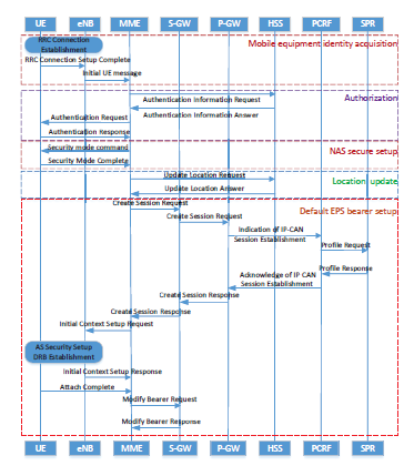 Figure 3: The initial attachment procedure in the LTE/EPC
4.1.2 Initial attachment in NOS-EPC
There are 4 types of sub-DGCs (named as InitialCtrl, AuthCtrl, SecuCtrl, and BearerSetup) involved during the initial attachment procedure in NOS-EPC. The InitialCtrl, AuthCtrl, and SecuCtrl cover the former three phases (i.e., MEIA, Authorization, and NAS secure setup). The BearerSetup covers the latter two phases. The resources (i.e. VMs’ CPU and memory) and the dependencies for the DGCs/sub-DGCs are managed by the M-models, which ensures that the user signaling is processed with a right order.
The M-modules allocate the resources (i.e. VMs CPU and memory) for the above sub-DGCs. Dependencies among DGCs/sub-DGCs are determined by the orchestration module, which ensures that user signaling is processed with a right order. In traditional LTE/EPC, the functions related to mobile equipment identity acquisition and NAS security setup phases are centralized in the MME. Therefore, InitialCtrl and SecuCtrl simply play the roles of MME during the procedure. The modifications are focused on the other phases. We mainly details the operations of AuthCtrl and BearerSetup.
MEIA and NAS security setup phases. In traditional LTE/EPC, the functions related to MEIA and NAS security setup phase are located in the MME. We separate these functions from the MME and organize them into the InitialCtrl and SecuCtrl, respectively.
The signaling interactions associated with InitialCtrl and SecuCtrl are plotted in Figure 4. In order to maintain the compatibility with traditional LTE/EPC, signaling contexts in NOS-EPC keep unchanged.
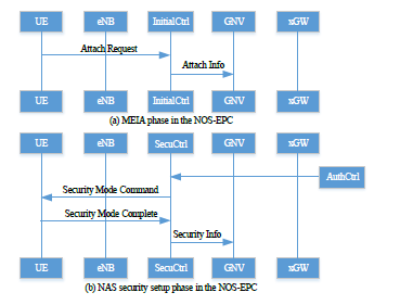 Figure 4: MEIA and NAS security setup phase in the NOSEPC
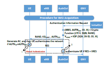 Figure 5: Authentication phase in the NOS-EPC
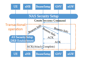 Figure 6: The default bearer setup phase in the NOS-EPC
The authentication phase. In the NOS-EPC, the authentication functions originally dispersed in the MME and HSS are centralized into AuthCtrl. The authentication process in LTE consists of two steps: authentication vector (AV) acquisition and mutual authentication. AV is a quadruple, containing XRES, AUTN, KASME, RAND. The AuthCtrl generates the AV with two steps, similar to HHS. First, the AuthCtrl calculates XRES, AUTNHSS with a random value RAND.
Next, it uses the key derivation function (KDF) to derive KASME. During the mutual authentication, UEs authenticate the network with RAND and AUTNHSS (the circle marked with 1 in Figure 5). A RES is then produced if the network has been authenticated (i.e.,
AUTNHSS=AUTNUE, where AUTNUE is calculated with RAND and AUTNHSS). The network authenticates the
UEs by comparing RES and XRES (the circle marked with 2 in Figure 5). In the end, the results are synced to GNV for the records. The details of the signaling interactions for authorization in NOS-EPC are shown in Figure 5.
The location update and default EPS bearer setup. The functions involved in these two phases are originally distributed among HSS, MME, S-GW, P-GW, PCRF, and SPR. In the NOS-EPC, they are reorganized into the BearerSetup. A create session command would be sent by the GNV to the sub-DGCs (BearerSetup). The create session command contains all the necessary information to establish a bearer, including the information in the traditional ”update location answer”, ”profile response” and so on. Once the BearerSetup receives the signaling, it carries out the bearer establishment algorithm, producing the bearer contexts. Then the bearer contexts are disseminated to the U-plane (UE, eNB, xGW) simultaneously. The bearer contexts for different entities are heterogeneous. The signaling interactions involved by BearerSetup in NOS-EPC are shown in Figure 6. The results (bearer context) of the sub-DGCs (BearerSetup) would be updated to the GNV to ensure the completeness.
4.2 Service request
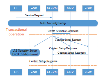 Figure 7: The service request procedure in the NOS-EPC
The service request could be trigged by UEs (uplink transmission) or network (downlink transmission). In this paper, we emphasis the procedure trigged by UEs in Figure 7. The procedure is executed when UEs wants to use a service from the Internet or the PDN networks.
We first focus on the signalling flows during the service request procedure. The main purpose is to setup a data forwarding path between the UE and its destination. The procedure is initiated when a service request message is sent to BearerSetup. Once BearerSetup receives the service request messages, it performs an integrity check on NAS-MAC. If the authentication check is passed, BearerSetup obtains the user-service-related information from GNV, including the UE subscription levels, requested service types, overall network congestions. According to these information, BearerSetup setups the forwarding path by distributing the context setup requests. The context setup requests include the IDs (i.e., TEIDs, bearer IDs), which identify the traffic channels for different UEs among NEs.
The establishment of data forwarding path involves resource allocation, e.g., routing scheduling, QoS mechanism, etc. On the aspect of route scheduling, efforts can be made to improve the capacity of U-plane. Since SDN and NFV technique are used, NOS-EPC is highly programmable. Adaptive routing strategies can be adopted to reduce the congestions by configuring the flow tables. Examples can be found in [24, 25], in which operators jointly optimize task routing and cloud selection to improve the system cost. Meanwhile, the implementation is more convenient in NOS-EPC owing to GNV, which has a global view of the network. BearerSetup can direct the traffic by configuring the flow table in the U-plane, bypassing the congestion links and improving the transmission capacity [26]. Other than routing strategy, advanced resource allocation algorithms or framework like [14, 15] can be migrated into NOS-EPC directly.
Resource allocation is another main concern since QoS mechanisms need to be incorporated to support multiple services with different QoS requirement. To support the legacy of LTE/EPC, conventional QoS mechanisms are fully migrated to NOS-EPC. In order to assign network resources to the traffic of each UE and manage them properly, BearerSetup acquires the subscriptions of UEs and services from GNV through create session command. BearerSetup first classifies user traffic into different service data flows (SDFs). Each SDF contains the flows with the same QoS parameters, e.g., QCI. Different QoS parameters are meant for different priorities of traffic flow which is shown in Table 1. BearerSetup appends QoS rules into Contest setup requests. The enforcement of QoS rules on NEs in the U-plane is the same as the cases in LTE/EPC, which is detailed in [23].
4.3 X2 Handover
4.3.1 Handover in LTE/EPC
X2 handover allows a UE to move from a serving cell to a neighbor cell and reestablish a new radio resource connection(RRC)[27]. Before the handover, the UE collects measurement reports about the signal strength and the quality of adjacent cells, and sends them to the source eNodeB(SeNB). SeNB determines whether the UE initiates handover to a target eNodeB(TeNB) or not. Three phases of handover are successively carried out.
Table 1: The procedure duration in different architectures
|
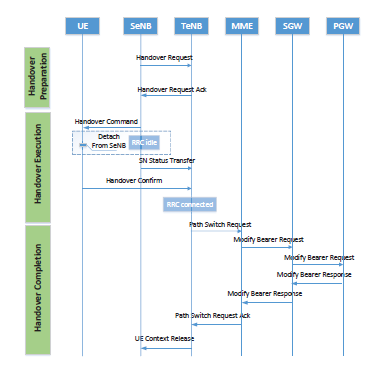 Figure 8: The signaling flow for X2 handover in LTE/EPC
Phase 1: Handover preparation. SeNB forwards the UE context along with S1 TEID to TeNB, assisting with the uplink from TeNB to SGW. The SeNB TEID is sent to TeNB to establish the X2 transport bearer, through which TeNB receives downlink packets while UE attempts to attach TeNB.
Phase 2: Handover execution. SeNB informs the UE to perform handover by sending a message related to TeNB. The message includes cells radio network temporary identity, access stratum security algorithm, etc. The UE detaches from SeNB and access TeNB, in the meantime the RRC connection is required to be reconfigured.
Phase 3: Handover completion. When the UE has been connected to the target cell, TeNB is obligated to inform MME to modify the bearer path accordingly. TeNB transmits its TEID to SGW and PGW via MME.
The response has to double back. SGW sends the downlink packets to TeNB through the newly established downlink bearer.
Consider the latency during the handover procedure in LTE/EPC. The latency could be presented in
![]() where DX2, DRRC, DS1, DS11, and DS5/8 are the latency motivated by X2, RRC, S1, S11, and S5/8, respectively. It is noticed that (1) assume successful transmission at first attempt. The actual delay values can be higher if some steps require re-transmissions.
where DX2, DRRC, DS1, DS11, and DS5/8 are the latency motivated by X2, RRC, S1, S11, and S5/8, respectively. It is noticed that (1) assume successful transmission at first attempt. The actual delay values can be higher if some steps require re-transmissions.
4.3.2 Handover in NOS-EPC
In NOS-EPC, the control functions are converged into GC-VMs. We use eNB-U represents eNB that exclusively retains user functions. The handover-related GCVMs control the handover procedure, which is shown in Figure 9.
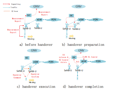 Figure 9: The Handover procedure in NOS-EPC
Initially, an UE reports its measurement to the network. Next, GC-VM accesses users’ information from GNV and makes the handover decision. The decision determines when and where to perform the handover procedure. Also, it points out which target cell the UE is about to attach.
Phase 1: Handover preparation. When the TeNB is determined, GC-VM pass the handover execution information to SeNB. Also, GC-VM dispatches TEID of SeNB and xGW to the TeNB. The former TEID is for
X2 transport downlink bearer setup. The latter one is for the establishment of an xGW uplink bearer. The setup of X2 transport downlink bearer ensures that the data could be buffered in target base station during the handover execution.
Phase 2: Handover execution. Once receiving the handover command from GC-VM, the UE obtains the information (e.g., access stratum keys) for attaching to the TeNB. There are no packet transmissions until it successfully accesses to TeNB. Packets from PDN are temporarily stored in the TeNB. The state of nonaccess stratum layer on UE remains unchanged during the handover execution. The radio link connection is inactive. Then, TeNB connects to the UE with access stratum security algorithms.
Phase 3: Completion. Once the UE connects to the TeNB, it informs the GC-VM that the handover procedure is completed. Then, GC-VM instructs SeNB to release the UE context and delete the previous tunnel (i.e., the tunnel between xGW and SeNB). Meanwhile, GC-VM distributes TeNB’s TEID to xGW, which helps to establish the downlink bearer from xGW to TeNB. Also, the instantaneous location and the context of UE are updated to GNV.
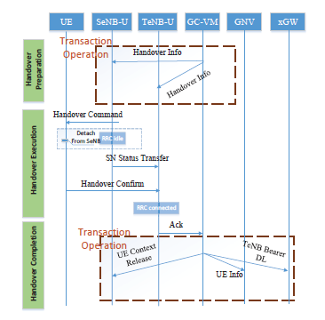 Figure 10: The Signaling flow for X2 handover in NOS-EPC
Consider the latency during the handover procedure in LTE/NOS-EPC. The latency could be presented in (2)
![]() where DRRC and DX2 are the latency motivated by RRC and X2. DTO is the latency incurred by transaction operation. DCU is latency between eNB and GC. The actual delay values can be higher if some steps require re-transmissions.
where DRRC and DX2 are the latency motivated by RRC and X2. DTO is the latency incurred by transaction operation. DCU is latency between eNB and GC. The actual delay values can be higher if some steps require re-transmissions.
4.4 detach
In the detach procedure, the UE is detached/detaches from the network he attached to. After this procedure, the network resources associated with the UE are completely released.
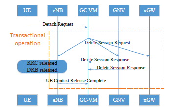 Figure 11: The detach procedure in NOS-EPC
The detach procedure in NOS-EPC is shown in Figure 11. It is an inverse operation of initial attachment. We assume that the detach procedure is triggered by the UE. Initially, the UE sends the detach request to the GC-VMs. The detach request mainly contains the GUTI and detach type of UE. Once the GC receives the detach request, it dispenses the delete session requests to eNB, GNV, and xGW simultaneously. The requests send to different NEs are heterogeneous, e.g., the request sent to eNB contains the ‘detach accept’ to the UE. These NEs (i.e., eNB, GNV, and xGW) delete the local context about UEs, i.e., network resources and return the response messages to GC-VM.
4.5 The Incorporation of new applications/services in NOS-EPC
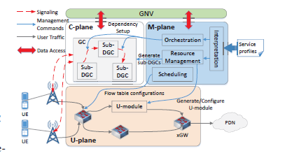 Figure 12: The integration of innovative applications in NOSEPC
The process of integrating a new application/service in NOS-EPC is shown in Figure 12. First, the service provider submits the profiles into the M-plane through the interpretation module. The profiles contain the functions and the requirements of the new application/service. The interpretation module is essentially a man-machine interface, which analyzes the profiles and generates a series of commands. The control functions are constructed as DGCs/sub-DGCs. The user functions are constructed as U-plane modules. The dependency among modules is configured into NE’s flow tables. The meta information (e.g., traffic template) are synced into the GNV.
5. The comparisons between NOSEPC and the other EPC solutions
In this section, we compare our solutions with the traditional EPC and the SDN-based EPC in order to analyze the pros and cons of our NOS-EPC. Firstly, we brief the architectures of traditional EPC and SDN-based EPC.
Table 2: Comparisons between different architectures
| LTE | SDN-EPC | NOS-EPC | |
| OPEX | High | Med | Low |
| Scalability | Low | Low | High |
| Flexility | Low | Med | High |
| Overheads | Med | High | Low |
| Capability | Low | High | High |
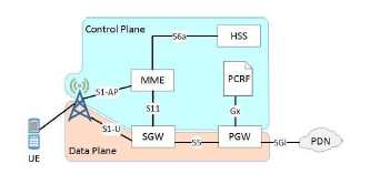 Figure 13: The architecture of the traditional LTE/EPC
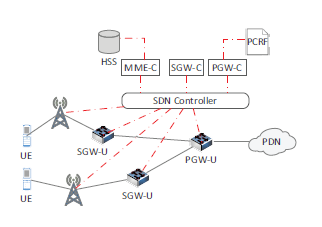 Figure 14: The architecture of the EPC based on SDN
The architecture of traditional LTE/EPC is shown in Figure 13. The details could be referred to [28]. The SDN-based architecture is shown in the Figure 14. In SDN-EPC, the control plane and data plane are decoupled by an SDN controller (i.e. floodlight). NEs (i.e. MME, SGW-C, SGW-P) in the control plane are implemented as SDN applications. The functions in the data plane are achieved with the extended SDN+ switches. The architecture of SDN-EPC could be referred to [29].
Table 2 compares these three architectures, covering OPEX, flexibility, scalability, signaling overheads, and user traffic transmission capability. We detail the comparisons as followings.
OPEX: The NEs (i.e. MME, SGW, PGW, HSS, SPR) in the traditional EPC are deployed on dedicated hardware. The special-designed hardware for different NEs increases the cost of procurement. The NOS-EPC and the control plane of SDN-EPC apply the virtualization technique. Commercial servers are used, which means the OPEX could be reduced.
Flexibility: Flexibility refers to the ability of adaption. In the traditional EPC, any modifications require considerations for the entire system because of the distributed control. The control paradigms in SDN-EPC are not changed compared with traditional LTE network. Therefore, the SDN-EPC has the exact same problems. On the other hand, in our NOS-EPC architecture, innovative services could be easily incorporated, as we described earlier. Thus, the flexibility of the proposed NOS-EPC is more superior.
Scalability: In order to improve the capabilities of the traditional EPC, operators usually need to replace the NEs with more powerful appliances. The replacements need to be accomplished locally and manually. Moreover, the traditional EPC typically scale vertically [29], which means the enhancements could not target at specific services. SDN-EPCs have similar issues. However, it would be easier in the SDN-EPC due to virtualization. Unfortunately, the SDN-EPC introduces bottleneck nodes (SDN controllers) between the control plane and the user plane. The scalability would be largely affected by the capacity of bottleneck nodes. Although some advanced techniques are proposed to deploy SDN in a large-scale network, there are still some problems need to be solved so far [30].
In the NOS-EPC, the ‘logical centralized’ GNV can be deployed as distributed databases, which has been widely used in the commercial market [21]. Supported by GNV, it is quite convenient to enhance system capacity by deploying replicas of modules and DGCs. Moreover, system enhancements can be accomplished remotely and automatically due to the existence of Mplane and GNV. Horizontally scaling of the EPC could be achieved through the duplications of the related DGCs/sub-DGCs or U/M-modules. The access loads on GNV could be relieved by distributed deployment (distributed databases).
Distinct from the SDN-base architecture, in NOSEPC, the capacity of the connections between different planes (U/C/M plane) would not be limited by a single node (or host/server). The diagnosis modules and the scheduling modules would automatically route the traffic to bypass the congestion links.
Signaling overheads: The distributed control in the traditional EPC or SDN-EPC contributes the coordination signaling and complicated handshakes among NEs. Additionally, in SDN-EPC, more signaling and handshakes are needed due to the separations of PGW and SGW. On the other hand, in our proposed NOS-
EPC, the logic for a particular LTE procedure or service is encapsulated into DGCs/sub-DGCs. The signaling overheads introduced by cooperation and handshakes are cutoff. The performance of the NOS-EPC would be considerably improved.
Moreover, in LTE, the signaling is delivered layer by layer. For example in the handover procedure, the signaling is successively enforced to MME, SGW and PGW when TeNB establishes bearers between SGW/PGW. However, in the NOS-EPC, signaling interactions among NEs is no longer constrained by layers. Thus, signaling overheads and handshakes are significantly cut down. In fact, LTE/EPC requires 12 signaling interactions during the handover. However, in NOS-EPC, only 9 interactions are required.
Transmission capability: In the EPC, packet loss is typically unacceptable. In traditional EPC, more resources (i.e. bandwidth, links, etc.) need to be provisioned to ensure the reliability. In dynamic network surroundings, performance degradation due to congestion is inevitable even with more resources. In SDN-EPC and NOS-EPC, the traffic routes could be optimized globally. A proper control can improve the average link utilization from 30%∼40% to nearly 100%[31].
There are some costs for our NOS-EPC as well. The replacements of dedicated hardware with commodity servers lead to consistent degradation (nearly 7% degradation [32]) on the aspect of the processing capacity. Second, the deployments of GNV need to be further investigated.
6. Performance evaluations
In this section, we evaluate the performance of the NOS-EPC. We mainly concentrate on the performance of C-plane in different architectures (traditional
EPC/EPC, SDN-EPC, and NOS-EPC). We compare the network efficiency on procedure durations (i.e., latency) and signaling overheads. The comparisons highlight the superiority of NOS-EPC on the aspects of procedure performance and network efficiency. The results also suggest that the NOS can help to build a promising cellular network. The comparisons are conducted with NS3.
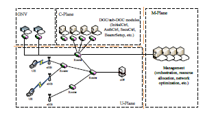 Figure 15: Simulation setting for NOS-EPC.
In the simulations, we use Cost266 as the network topology of NOS-EPC [33]. We assume that nodes in Cost266 are equipped with computation resources. We deploy sub-DGCs/DGC (e.g., InitialCtrl, SecuCtrl, Authctrl, and BearerSetup), U/M modules, and GNV as NS3 applications on separate nodes. eNBs are added which connects the nodes in Cost266. We deploy eNBs in a line with different cell size (Rcell), connecting the nodes in Cost266. A complete NOS-EPC is then built as Figure 15. The bandwidth of links between the nodes is uniformly configured as 1Gbps.
UEs in Figure 15 are also implemented with nodes in NS3. In this paper, we mainly focus on the latency and signaling overheads motivated by initial attachment, service request, handover, and detach procedure. Thus, we set that each UE attaches to the EPC with an average interval equalling 250 ms. Once an initial attachment procedure is triggered, the following procedures (service request, detach) are sequentially invoked. The handover procedure is initialized when UE moves out of the current eNB’s coverage. We change the number of UEs to vary workloads of EPC. In the simulations, UEs move on a line with different speed (VUE). The parameters for the simulations are summarized in Table 3.
We carry out the simulations in both static scenarios (without UE mobility) and dynamic scenarios (with UE mobility). In static scenarios, we rule out the influences brought by UE mobility and address the performance of initial attachment, service request, and detach. In dynamic scenarios, we focus on the influences under different cell size and UE velocity.
We first evaluate the performance in a static environment (VUE = 0). Table 4 shows the procedure duration in different architectures. The percentages in parentheses tell the ratios using the traditional EPC as the baseline. The variances of the duration in the table indicate the jitters of the procedure duration. From the points of average duration and jitters, the NOS-EPC takes advantages. Compared with the traditional EPC, the NOS-EPC could decrease the procedure duration by nearly 42.5%. On the other hand, the SDN-EPC shows its degradation about 27.5%. The average procedure duration is mainly affected by the number of interactions among different NEs. The number of interactions in different architectures is shown in Table 5. In this table, each transaction operation is viewed as an interaction. It could be seen that NOS-EPC decreases the signaling overheads by at least 25% compared to LTE/EPC. On the other hand, the SDN-EPC suffers from redundant signaling overheads due to its crude U/M decoupling.
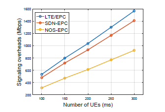 Figure 16: The signaling overheads in different architectures.
Figure 16 shows the signaling overheads in different architectures, which coincides with the conclusions implied by Table 5. It proves that our NOS-EPC could sufficiently decrease the signaling overheads. The reductions in NOS-EPC could be as much as 35% com-
Table 3: Simulation parameters
| Description | Values |
| UE number | 100∼300 |
| Average interval of initial attachment | 25 ms |
| UE velocity (VUE) | 0 ∼ 40 m/s |
| Cell size (Rcell) | 150 ∼ 400 m |
| Link bandwidth | 1 Gbps |
Table 4: The procedure duration in different architectures
Number of users Average duration (ns) Variance
Table 5: The number of interactions in different architectures
| Initial attach | Detach | Service request | Handover | |
| LTE EPC | 19 | 6 | 6 | 12 |
| SDN EPC | 23 | 10 | 10 | 16 |
| NOS-EPC | 10 | 3 | 3 | 6 |
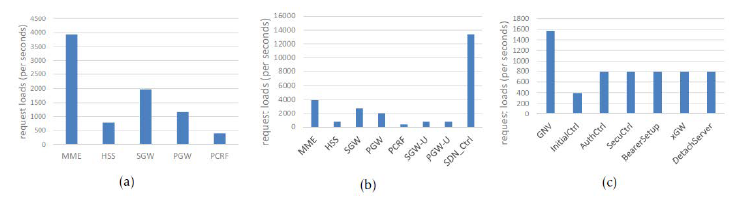 Figure 17: The request loads on the NEs in different architectures. The loads are measured in the simulations with 10 UEs. (a) shows the loads on the NEs in traditional EPC. (b) shows the loads of the NEs in SDN-EPC including the SDN controllers. (c) shows the cases in NOS-EPC. The strings in x label denote the name of sub-DGCs in the C-plane.
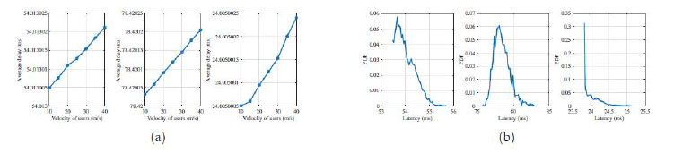 Figure 18: The handover latency in different architectures. (a) The handover latency with different UE velocity when Rcell = 150m. (b) The probability distribution function (PDF) of handover latency with VUE = 40m/s and Rcell = 150m.
pared with traditional EPC. The signaling overheads also influences the jitters. The queue delays (as random variables) become significant as the overheads increases. Therefore, the jitters of transmissions become larger.
Figure 17 shows the request loads for different NEs in three architectures with VUE = 0. In traditional EPC, the pressure on the MME is the heaviest. In the SDN-EPC, the bottleneck node (SDN controller) has the highest request loads. Other than GNV, the distribution of request loads in NOS-EPC is nearly balanced. The heavy loads on GNV could be relieved if the GNV is deployed in a distributed manner. The requests loads on different NEs imply the scalability of different EPCs. The SDN controller and MME would become the bottlenecks in SDN-EPC and traditional EPC, respectively. In the NOS-EPC, things become less tricky due to virtualization and nature of the architecture. The distributions of loads on different NEs also affect the duration. A congested path would largely increase the variance of the latency [34]. With a heavy loaded SDN controller, the jitters in NOS-EPC are more significant. The results are agreed with prior results (jitters) in Table 4.
In order to emphasis NOS-EPC performance in a dynamic environment, we evaluate the performance of NOS-EPC. We vary VUE and Rcell in the range of 5 ∼ 40m/s and 150 ∼ 400m, respectively.
Figure 18(a) plots the tendency of handover latency with different UE velocity. It shows that the average handover delay stays about 54.01ms, 78.42ms, and 24.00ms in LTE/EPC, SDN-EPC, and NOS-EPC, respectively. The delay slightly increases with the UE velocity since a higher VUE results in higher congestion in EPC. The proposed architecture (NOS-EPC) reduces the delay by nearly 55.5% compared to the LTE/EPC. The benefit is owing to the redesigns of the control paradigm. Redundant signaling interactions are cut off due to the centralized control. On the other hand, SDN-EPC has the longest handover delay. The reason is that more signaling overheads are required due to the sync between SGW(or PGW) and SGW-U(or PGW-U).
Figure 18(b) compares the latency distributions of handover procedure in different architectures. The left graph is for the handover procedure in LTE/EPC. The middle one represents the case in SDN-EPC and the right graph is the case in NOS-EPC. The shapes of the curves in Figure 18(b) tells the probability distributions of the handover procedure. Moreover, the peaks of the curves describe the number of network backlogs. When the network suffers severe congestion (backlogs), the queue delay on NEs increases, shifting the peaks to the rightwards. Vice Versa. Therefore, the procedure in NOS-EPC causes fewer network backlogs than the other network architectures.
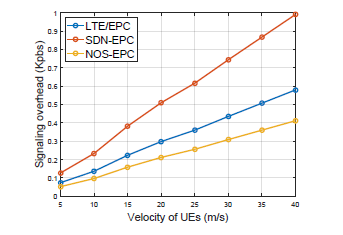 Figure 19: The signaling overheads brought by a single UE with different VUE. We set Rcell = 150m.
Figure 19 shows the relationships between the signaling overheads and VUE. As VUE increases, the handover procedure is invoked more frequently, which increases the signaling overheads. Compared with LTE/EPC, the proposed NOS-EPC could always cut off the signaling overheads by nearly 28.8%. In NOS-EPC, the overall information elements in handover signaling decrease from 373 bytes to 265 bytes. The SDN-EPC take more signaling overheads compared to LTE/EPC and SDN-EPC since it requires additional signaling to sync the U/C plane, e.g., PGW and PGW-U, SGW and SGW-U.
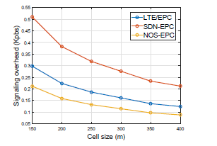 Figure 20: The signaling overheads brought by a single UE with different Rcell. We set VUE = 10m/s.
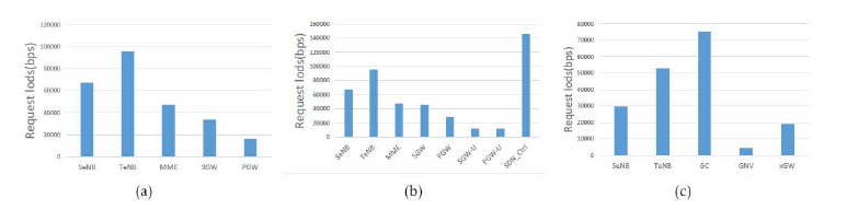 Figure 21: The request load brought by handover in different architectures. The loads are measured in the simulations with 2000 UEs. (a) shows the loads on the NEs in traditional EPC. (b) shows the loads on the NEs in SDN-EPC including the SDN controllers. (c) shows the cases in NOS-EPC.
Figure 20 plots the relationships between the signaling overheads and Rcell. A small-size cell requires frequent handovers. As Rcell increases from 200m to 400m, the handover times decrease by nearly 54.4%. Therefore, when Rcell increases, signaling overheads decreases. Coincided with former analysis, the overheads in NOS-EPC decrease by nearly 28.8% compared to LTE/EPC. Meanwhile, SDN-EPC performs the worst owing to a roughly decouple between U-plane and C-plane.
Figure 21 shows the overheads on NEs in different architectures. Similar to the static scenarios, the proposed NOS-EPC shows relatively balanced distributions. In LTE/EPC and SDN-EPC, MME and SDN controller are the bottlenecks which would significantly degenerate the system performance. The heavy load on these NEs would result in additional network cost, such as packet loss, workload expiration, etc. On the other hand, the load in NOS-EPC is nearly balanced. Moreover, supported by GNV, the capacity of NEs could be easily enhanced by the duplication of NE instances.
7. Conclusion
In this paper, we proposed an innovative EPC architecture based on NOS framework, which consists of the Uplane, C-plane, M-plane, and GNV. We describe the operation of the NOS-EPC with four common EPS mobility management(EMM) procedures, i.e., initial attachment, service request, handover and detach. We detail the comparison among conventional LTE/EPC, SDNEPC, and the proposed NOS-EPC on OPEX, scalability, flexibility, signaling overheads, and transmission capability. Compared to the conventional LTE/EPC, the proposed NOS-EPC takes advantages since we loosely decouple the U/C/M plane through GNV. C/M plane is carefully designed to deliver a centralized control. The GNV is deployed in a distributed manner. Thus, no bottleneck node exists in the proposed architecture compared to the SDN-EPC. The simulations verify that compared with LTE/EPC and SDN-EPC, NOS-PEC could significantly decrease the signaling overheads (by at least 35%) and procedure duration (by at least 42%). Moreover, we conduct the simulations to evaluate the workload on different NEs. The results show that the load distribution in NOS-EPC is nearly balanced. On the other hand, LTE/EPC and SDN-EPC suffer from severe congestion on MME and SDN controller, which decreases the performance on scalability. The advantages on the scalability, programmability and the improvements of the procedure duration, signaling overheads, and loads distribution mean that the NOS-EPC is a promising solution for the B5G network. In the future work, we will focus on the division granularity of the GC modules and GNV, which can be further optimized to enhance the performances of the network. Moreover, a testbed for NOS-EPC evaluation would be developed.
Acknowledgment
This work is supported by the National S&T Major Project(No.2018ZX03001004).
- S. Sekander, H. Tabassum, and E. Hossain, “Multi-Tier Drone Architecture for 5G/B5G Cellular Networks: Challenges, Trends, and Prospects,” IEEE Communications Magazine, 56(3), 96-103, March 2018.
- S. Abdelwahab, B. Hamdaoui, M. Guizani, and T. Znati, “Network function virtualization in 5G,” IEEE Communications Magazine, 54(4), 84-91, April 2016.
- E. J. Kitindi, S. Fu, Y. Jia, A. Kabir, and Y. Wang, “Wireless Network Virtualization with SDN and C-RAN for 5G Networks: Requirements, Opportunities, and Challenges,” IEEE Access, 19099-19115, May 2017.
- Q. Duan, N. Ansari, and M. Toy, “Software-defined network virtualization: an architectural framework for integrating SDN and NFV for service provisioning in future networks,” IEEE Network, 30(5), 10-16, Sep. 2016.
- B. Wu, L. Ge, J. Zeng, X. Zheng, Y. Kuang, X. Su, and J. Wang, “An Innovative EPC with Not Only Stack for beyond 5G Mobile Networks,” 2018 IEEE 87th Vehicular Technology Conference (VTC Spring), 1-5, June 2018.
- K. Pentikousis, Y. Wang, and W. Hu, “Mobileflow: Toward software-defined mobile networks,” IEEE Communications Magazine, 51(7), 44-53, Jul. 2013.
- J. Liu, T. Zhao, S. Zhou, Y. Cheng, and Z. Niu, “CONCERT: a cloud-based architecture for next-generation cellular systems,” IEEE Wireless Communications, 21(6), 14-22, Dec. 2014.
- I. F. Akyildiz, P. Wang, and S.-C. Lin, “SoftAir: A software defined networking architecture for 5G wireless systems,” Computer Networks, 85, 1-18, 2015.
- X. Sun and N. Ansari, “Green cloudlet network: A distributed green mobile cloud network,” IEEE Network, 31(1), 64-70, Jan. 2017.
- S. Shanmugalingam and P. Bertin, “Programmable Mobile Core Network,” 2014 IEEE Symposium on Computers and Communications (ISCC), 1-7, June 2014.
- T. Taleb, M. Corici, C. Parada, A. Jamakovic, S. Ruffino, G. Karagiannis, and T. Magedanz, “EASE: EPC as a service to ease mobile core network deployment over cloud,” IEEE Network, 29(2), 78-88, March 2015.
- M. R. Sama, S. B. H. Said, K. Guillouard, and L. Suciu, “Enabling network programmability in LTE/EPC architecture using OpenFlow,” 2014 12th International Symposium on Modeling and Optimization in Mobile, Ad Hoc, and Wireless Networks (WiOpt), 389-396, May 2014.
- V. Nguyen and Y. Kim, “Proposal and evaluation of SDN based mobile packet core networks,” EURASIP Journal on Wireless Communications and Networking,2015(1), 172-190, 2015.
- V. D’Amico, A. Lombardo, M. Melita, C. Rametta, and G. Schembra, “An SDN/NFV telco operator platform for video broadcasting,” IEEE Communications Magazine, 54(10), 122- 128, Oct. 2016.
- J. Costa-Requena, A. Poutanen, S. Vural, G. Kamel, C. Clark, and S. K. Roy, “SDN-Based UPF for Mobile Backhaul Network Slicing,” 2018 European Conference on Networks and Communications (EuCNC), 48-53, June 2018.
- X. An,W. Kiess, J. Varga, J. Prade, H. Morper, and K. Hoffmann, “SDN-based vs. software-only EPC gateways: A cost analysis,” 2016 IEEE NetSoft Conference and Workshops (NetSoft), 146- 150, June 2016.
- E. B. Hamza and S. Kimura, “A Scalable SDN-EPC Architecture Based on OpenFlow-Enabled Switches to Support Inter-domain Handover,” 2016 10th International Conference on Innovative Mobile and Internet Services in Ubiquitous Computing (IMIS), 272-277, July 2016.
- S. Zhou, T. Zhao, Z. Niu, and S. Zhou, “Software-defined hypercellular architecture for green and elastic wireless access,” IEEE Communications Magazine, 54(1), 12-19, Jan. 2016.
- J. Zeng, X. Su, J. Gong, L. Rong, and J. Wang, “5G virtualized radio access network approach based on NO Stack framework,” Communications (ICC), 2017 IEEE International Conference on, 1-5, IEEE, 2017.
- A. Basta, W. Kellerer, M. Hoffmann, K. Hoffmann, and E. Schmidt, “A Virtual SDN-Enabled LTE EPC Architecture: A Case Study for S-/P-Gateways Functions,” 2013 IEEE SDN for Future Networks and Services (SDN4FNS), 1-7, Nov. 2013.
- G. DeCandia, D. Hastorun, M. Jampani, G. Kakulapati, A. Lakshman, A. Pilchin, S. Sivasubramanian, P. Vosshall, and W. Vogels, “Dynamo: Amazon’s Highly Available Key-value Store,” SIGOPS Oper. Syst. Rev., 41(6), 205-220, Oct. 2007.
- J. C. Corbett, J. Dean, M. Epstein, A. Fikes, C. Frost, J. J. Furman, S. Ghemawat, A. Gubarev, C. Heiser, P. Hochschild, W. Hsieh, S. Kanthak, E. Kogan, H. Li, A. Lloyd, S. Melnik, D. Mwaura, D. Nagle, S. Quinlan, R. Rao, L. Rolig, Y. Saito, M. Szymaniak, C. Taylor, R.Wang, and D.Woodford, “Spanner: Google&Rsquo;s Globally Distributed Database,” ACM Trans. Comput. Syst., 31(2), 8:1-8:22, Aug. 2013.
- Netmanias, “EMM Procedure 1. Initial Attach – Part 2. Call Flow of Initial Attach.” https://www.netmanias.com/en/?m= view&id=techdocs&no=6102/. Accessed Jan. 16, 2014.
- A. Ceselli, M. Premoli, and S. Secci, “Mobile Edge Cloud Network Design Optimization,” IEEE/ACM Trans. Netw., 25(3), 1818-1831, June 2017.
- B. Yang, W. K. Chai, Z. Xu, K. V. Katsaros, and G. Pavlou, “Cost-Efficient NFV-Enabled Mobile Edge-Cloud for Low Latency Mobile Applications,” IEEE Transactions on Network and Service Management, 15(1), 475-488, March 2018.
- J. Hansen, D. E. Lucani, J. Krigslund, M. Medard, and F. H. P. Fitzek, “Network coded software defined networking: enabling 5G transmission and storage networks,” IEEE Communications Magazine, 53(9), 100-107, Sep. 2015.
- 3GPP TS 36.420 V14.0.1, “X2 general aspects and principles (Release 14),” 1, 0-14, 2017.
- U. Barth, “3GPP Long-Term evolution/system architecture evolution overview,” Alcatel White Paper, 2006.
- A. Jain, N. Sadagopan, S. K. Lohani, and M. Vutukuru, “A comparison of SDN and NFV for re-designing the LTE packet core,” Network Function Virtualization and Software Defined Networks (NFV-SDN), IEEE Conference on, 74-80, IEEE, 2016.
- T. Huang, F. R. Yu, C. Zhang, J. Liu, J. Zhang, and Y. Liu, “A Survey on Large-Scale Software Defined Networking (SDN) Testbeds: Approaches and Challenges,” IEEE Communications Surveys Tutorials, 19(2), 891-917, Secondquarter 2017.
- S. Jain, A. Kumar, S. Mandal, J. Ong, L. Poutievski, A. Singh, S. Venkata, J. Wanderer, J. Zhou, M. Zhu, J. Zolla, U. H¨olzle, S. Stuart, and A. Vahdat, “B4: Experience with a globallydeployed software defined WAN,” SIGCOMM Comput. Commun. Rev., 43(4), 3-14, Aug. 2013.
- D. Lake, G. Foster, S. Vural, Y. Rahulan, B. H. Oh, N. Wang, and R. Tafazolli, “Virtualising and orchestrating a 5G evolved packet core network,” 2017 IEEE Conference on Network Softwarization (NetSoft), 1-5, Jul. 2017.
- S. Orlowski, R. Wessily, M. Piro, and A. Tomaszewski, “SNDlib 1.0 Survivable Network Design Library,” Networks, 55(3), 276- 286.
- D. E. Comer, Computer networks and Internets. Prentice Hall Press, 2008.