Microstrip Patch Antenna for Ultra-Wideband Applications

Adv. Sci. Technol. Eng. Syst. J. 4(3), 10–15 (2019);
 DOI: 10.25046/aj040302
A new microstrip patch antenna for ultra-wideband applications is presented in this paper. The design and performance of the antenna component are discussed. The propounded antenna is mounted on a compact FR-4 substrate having dimensions 20 x 30 x 1.6 mm3 with relative permittivity εr=4.3. The rectangular patch antenna is slotted with two types; rectangular and semi-circle slots so as to ensure a broad bandwidth. The results reveal that the antenna covers the frequency range of 3.1–7.5 GHz with a reflection coefficient reduced to -55 dB and a maximum gain of 5.9 dB. The details of the simulated and measured results for reflection coefficient are presented, showing a good agreement between them. To analyze the effect of the slots, the surface current distribution is investigated. The performances of good impedance matching are achieved within the operating band. Simulations are performed using CST Microwave Studio. The propounded antenna can be deployed for UWB applications and other radio communication services systems such as high-resolution radar, military communication, communications and sensors, position location and tracking
1. Introduction
UWB technology has recently attracted significant attention in wireless communications thanks to its main features in particular high bandwidth and data rate, ensuring secure communication in military applications. The world of ultra-wideband (UWB) has changed in very recent history. In February 2002, the FCC (Federal communications commission) issued a ruling that UWB could be used for commercial applications on unlicensed basis as well as for radar and safety applications. The decision authorized very low power spectral density emission in a bandwidth ranging from 3.1 to 10.6 GHz [1-3]. UWB appears to be a technology very promising for wireless communications at very high levels data-rate, high-precision radar and imaging systems. UWB systems use short pulses (of the order of the picosecond), repeated at a certain rate that can be up to several giga-impulses per second, offering thus a very high bandwidth with a very low transmission power level. This offers UWB systems the possibility of coexisting with other systems.
To fulfill the demand in this type of communications, many research on UWB antenna design have been published. Most of them focused on patch antennas because of their simple structure, small size, low cost, low complexity, light weight, and high-speed data rate. They are considered as good candidates for UWB applications among many versions of UWB antennas. Nevertheless, micro-strip patch antenna has narrow bandwidth.
To resolve this problem and obtain the desired performances, many methods are used. The typical technique focus on cutting slots of several forms in the radiating element, the ground plane, and the feed line. Nowadays, many slot shapes are available and discussed by various researchers [4-6]. Slot antennas have proven to be useful in that context. However design and placement of these slots on the radiating element is challenging as compared to the other traditional techniques. The purpose of this project is to design a micro-strip patch antenna for UWB applications that covers the frequency range of 3.1–7.5 GHz.
2. Design and Configuration of the Antenna
The propounded antenna is a rectangular patch antenna which is fed by a micro-strip line and mounted on a dielectric substrate named FR4-lossy, with thickness h=1.6mm and relative permittivity εr=4.3, having dimensions of 20 x 30 x 1.6 mm3. These specifications for the substrate are a part of material parameters window on CST Microwave Studio. The material used in the patch and the ground is lossy copper with a thickness of Mt=0.035mm as given in Tab .1. The width of the line feeding is 3 mm and the length is 14.5 mm. The partial ground plane is also used with the propounded antenna geometry as shown in Figure 1. To investigate the impact of various antenna’s characteristics (different slots), a meticulous parametric study was performed. The parametric values of the propounded antenna are shown in Tab.1. The antenna is excited by a 50-Ω micro-strip feed line. The parameters measurement of the patch are calculated using the following formulas [7]:
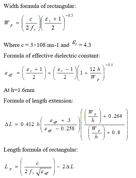 Table 1: Parameter values of the propounded antenna
| Parameters | Values (mm) |
| L | 30 |
| W | 20 |
| Lp | 7 |
| Wp | 16 |
| Lg | 14 |
| Wg | 20 |
| h | 1.6 |
| Mt | 0.035 |
| Wf | 3 |
| Lf | 14.5 |
| a | 10 |
| b | 1.5 |
| c | 4.5 |
| d | 2.5 |
| e | 1 |
| f | 8 |
| g | 1 |
| h | 0.75 |
| o | 0.5 |
| r1 | 2.5 |
To amplify the coupling between the feed line and the slots, multiple slots are introduced in order to broaden the operating bandwidth of the antenna. Having a quite large slot is logical transition to obtain wide bandwidth from an aperture-coupled patch. The first two slots are designed by combining rectangular and semi-circle slots placed in a juxtapose way [8-10]. In addition, different other rectangular slots are included in the radiating element. The structure of the antenna design is illustrated in Fig .1.
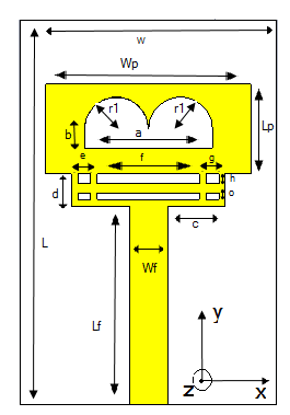
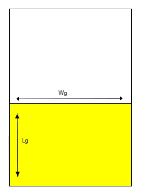 Figure 1 Design of the propounded UWB antenna (a) Top (b) Bottom
To improve the performance of micro-strip patch antenna, it is advisable to design a combination of two or more slots on the radiating element. This can be observed from the discussed literature survey that a micro-strip patch antenna with slots can be designed for wireless applications [11]. The technique employed in this paper retains the same elementary structure of the antenna with different slots included in the radiating element. In order to obtain a wide bandwidth, a rigorous investigation on different parameters in terms of feed width (Wf), feed length (Lf) and different slots width and length was performed. From the analysis we found the optimum dimensions of above parameters to be 3 mm, 14.5 mm respectively for the feed line, to meet the requirement. The slots dimensions and other antenna’s parameters are listed in Tab .1 on the basis of undertaken parametric analysis.
Figure 2 presents the simulated reflection coefficient of the antenna, the antenna without rectangular slots and the antenna without semi-circle slots. When different slots are included, a wide bandwidth is achieved from 3.1 to 7.5 GHz with three resonant frequencies at 3.9, 5.95 and 7.3 GHz. Effect of using different slots is shown. We notice that the propounded antenna is the best candidate to meet the requirements in terms of UWB bandwidth. The flow chart of the propounded antenna’s design methodology is presented in figure 3.
 Figure 2 Simulated reflection coefficient of the propounded antenna, the antenna without rectangular slot and the antenna without semi-circle slots
3. Results and Discussions
The propounded UWB antenna is designed by opting for the optimal values of above parameters in order to cover the frequency range 3.1- 7.5 GHz. Both numerical and experimental tests have been achieved to assess the effectiveness of the propounded antenna and the results are presented in this section. Toward this end, the antenna was fabricated on FR4-lossy substrate (30 x 20 x 1.6 mm3) with dielectric constant of Ɛr = 4.3. Figure 4 depicts the fabricated antenna for experimental verification.
The reflection coefficient of the antenna has been analyzed using CST Microwave STUDIO simulator and verified using another electromagnetic simulator HFSS as shown in Figure 5. A 3.1–7.5 GHz frequency range below -10 dB of return loss S11 is obtained. The reflection coefficient (S11), measured in decibel (dB), can be calculated using the formula:
Where Z0 is the characteristic impedance of the 50 Ω SMA port and Zin is the driving point impedance of the antenna. Figure 5 shows a comparison of the simulated reflection coefficient using both CST and HFSS. The results corroborate that there is a good agreement between the two simulations with a small variation as the two softwares use different numerical techniques, finite integration technique, a relative of FDTD for CST Microwave Studio and Finite Element Method (FEM) for HFSS [12].
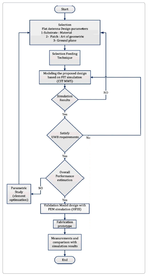 Figure 3 The flow chart of the propounded antenna’s design methodology.
 Figure 4 Photograph of the fabricated UWB antenna
The UWB antenna was measured after fabrication to examine the performance of the proposed approach. Measured reflection coefficient is achieved by vector network analyzer. The measured and simulated reflection coefficients of antenna are compared in Figure 6. From measured results, we can notice that the antenna is operating with a -10dB bandwidth from 3.1 to 7.5 GHz. A good agreement between simulation and measurement results is observed with a little discrepancy which is mainly owing to the fabrication margin. It could also be because to the impact of the feeding cable, feeding connector and the antenna fixation support as the structure is small.
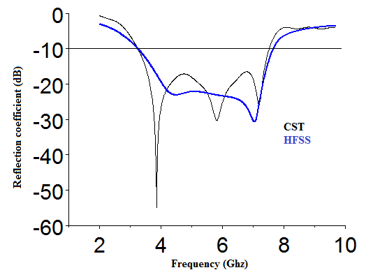 Figure 5 Simulated reflection coefficient of the propounded antenna
 Figure 6 Measured and simulated reflection coefficient of the UWB antenna
The electromagnetic solver, CST Microwave STUDIO, is used to numerically analyze and improve the antenna’s configuration. Figure 7 presents the simulated results of the propounded antenna with the rectangular slot combined with semi-circle slots width, from 0.5 to 1.5 mm. It should be noticed that one variable at the time was varied, the others being constant. It is apparent that the bandwidth for UWB band decreases as the width decreases from 1.5 to 0.5 mm. Consequently, it is concluded that b= 1.5 mm is the optimal value for the bandwidth from 3.1 to 7.5 GHz, covering the whole UWB range with three resonant frequencies at 3.9, 5.95 and 7.3 GHz.
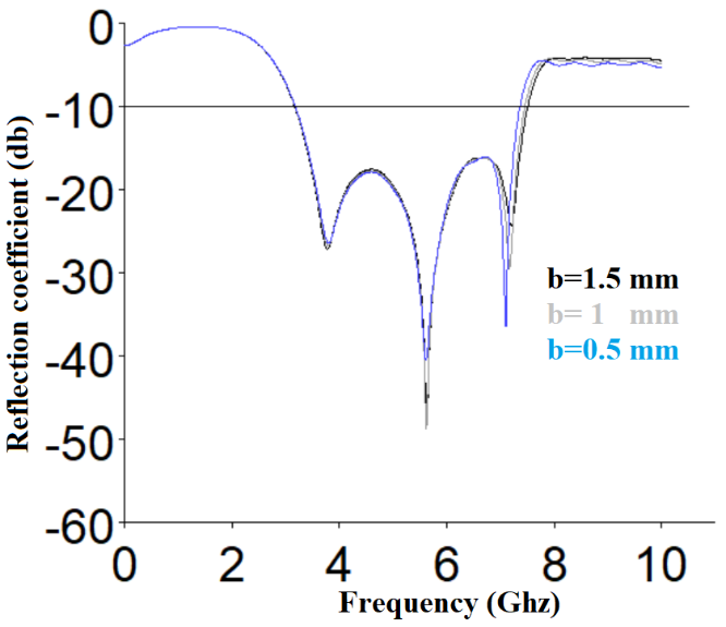 Figure 7 Simulated reflection coefficient response of the antenna as a function of “b”. All other parameters are the same as listed in Table 1
The propounded UWB antenna has an acceptable quasi omnidirectional radiation pattern needed to receive information signals from all directions. Figure 8 presents three-dimensional radiation patterns at three frequencies 3.9, 5.95 and 7.3 GHz. The gain of the antenna attain 3.26 dB at 3.9 GHz, 4.55 dB at 5.95 GHz and 5.90 dB at 7.3 GHz.
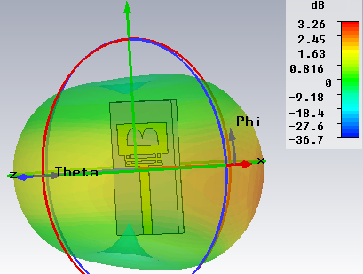
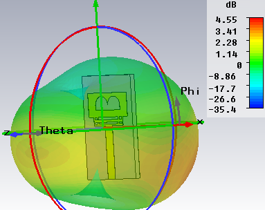
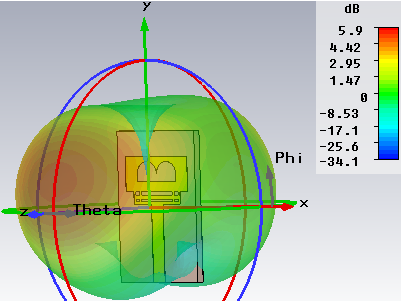 Figure 8. 3D radiation patterns of the propounded antenna at (a) 3.9, (b) 5.95 and (c) 7.3 GHz.

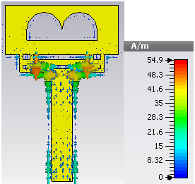
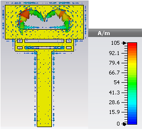 Figure 9 Surface Current distributions at (a) 3.9 GHz, (b) 5.95 GHz and (c) 7.3 GHz
Surface current distribution has been depicted in Figure 9 and analyzed at discrete frequencies (a) 3.9 GHz, (b) 5.95 GHz and (c) 7.3 GHz, to give a physical perception and have a deeper understanding on the resonant behavior of the antenna. Figure 9 (a) and (b) shows that the surface current distributions are mainly flow and distributed though along the rectangular slots and the feed part. From Figure 9 (c), it can be observed that most of surface currents are concentrated on the edges of the interior and exterior of semi-circle slots. Effective coupling between different slots affords wide-band matched impedance bandwidth, therefore, the surface current is distributed evenly over the radiating patch. The maximum gain of the propounded antenna is presented in Figure 10. As expected, the antenna has a good gain over the whole operating frequency range with a maximum gain up to 5.9 dB.
The simulated radiation efficiency of the antenna is presented in Figure 11. It can be noticed that the antenna reaches a maximum radiation efficiency of 81% and more than 60% over the whole UWB frequency range.
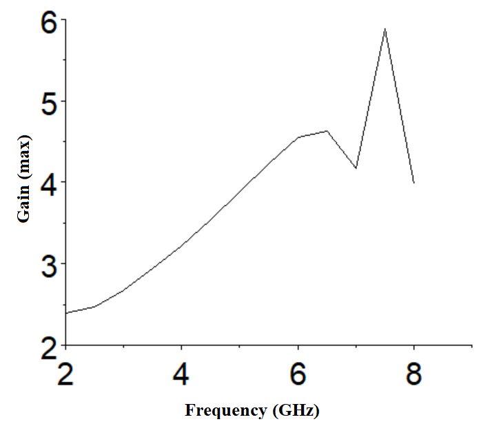 Figure 10 The gain of the propounded antenna
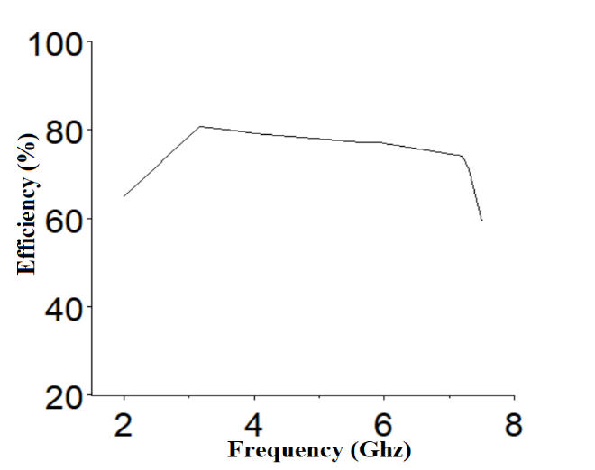 Figure 11 simulated radiation efficiency of the antenna
A comparison between our antenna and other published research is demonstrated in Table 2 in terms of their dimensions, bandwidth, gain and applications, in order to reinforce the concept of design. The almost stable radiation pattern with gain up to 5.9 dB makes our antenna suitable for being used for UWB applications.
Table 2 A comparison between the propounded antenna and other published work
| References | Dimensions
(in mm) |
Bandwidth
UWB |
Gain at resonant frequency (dB) | Applica-tions |
| [13] | 13×15 | 3.07-11.64 | 5.49 | UWB applications |
| [14] | 22×24 | 2.8-11.4 | 3.6
5.4 |
UWB applications |
| [15] | 27×32.42 | 3.1-5.2
5.8-10.6 |
2.33
5.49 |
UWB
applications |
| Our work | 20×30 | 3.1- 7.5 | 3.2
4.5 5.9 |
UWB applications |
4. Conclusion
The micro-strip patch antenna is easy to manufacture, replaceable, low profile and highly efficient. Such antennas are strongly recommended in satellite and wireless communication. In this paper, a new UWB patch antenna is presented with a wide bandwidth from 3.1 to 7.5 GHz with three resonant frequencies at 3.9, 5.95 and 7.3 GHz. The optimized structural parameters have been reached after many optimization and parameter sweeps on antenna performance. The propounded antenna can be used in multiple UWB applications that requires a wide bandwidth and reduced return loss at the operating frequency of the frequency range. The simulated results provide that, the maximum bandwidth attained numerically is 4.4 GHz due to the multiple slots used in the antenna. The results have revealed that our new fabricated antenna is definitely highly convenient for UWB applications such as high-resolution radar, military communication, communications and sensors, position location and tracking.
- Federal Communications Commission (FCC) “New Public Safety Applications and Broadband Internet Access among Uses Envisioned by FCC Authorization of Ultra-Wideband Technology”, February 2002.
- Federal Communications Commission (FCC), “Revision of Part 15 of the Commission’s Rules Regarding Ultra-Wideband Transmission Systems”, First Report & Order, Washington DC, February 2002.
- Chen, D. and C. H. Cheng, “A novel compact ultra-wideband (UWB) wide slot antenna with via holes,” Progress In Electromagnetics Research, Vol. 94, pp. 343–349, 2009. doi:10.2528/PIER09062306
- A. Ibrahim, M. A. Abdalla, and A. Boutejdar, “A Printed Compact Band-Notched Antenna Using Octagonal Radiating Patch and Meander Slot Technique for UWB Applications”, Progress In Electromagnetics Research M, Vol. 54, pp. 153–162, 2017. doi:10.2528/PIERM16122805
- Changzhou Hua, Yunlong Lu, and Taijun Liu, “UWB Heart-Shaped Planar Monopole Antenna with a Reconfigurable Notched Band”, Progress In Electromagnetics Research Letters, Vol. 65, pp. 123–130, 2017. doi:10.2528/PIERL16120203
- A. Pirooj, M. Naser Moghadasi, F. B. Zarrabi, and A Sharifi, “A Dual Band Slot Antenna for Wireless Applications with Circular Polarization”, Progress In Electromagnetics Research C, Vol. 71, pp. 69–77, 2017. doi:10.2528/PIERC16111401
- C. A. Balanis. Antenna Theory analysis and design. New York, 2007
- Kharakhili, F. G., M. Fardis, G. Dadashzadeh, A. Ahmadi, and N. Hojjat, “Circular slot with a novel circular microstrip open ended microstrip feed for UWB applications,” Progress in Electromagnetics Research, Vol 68, pp. 161–167, 2007. doi:10.2528/PIER06071901
- Marqués, R.; Mesa, F.; Martel J.; Medina, F. “Comparative analysis of edge and broadside coupled split ring resonators for metamaterial design: Theory and experiment”. IEEE Transactions on Antennas and Propagation, Vol. 51, No. 10, pp. 2572-258, October 2003. DOI: 10.1109/TAP.2003.817562
- I. Latif, L. Shafai and S. K. Sharma, “Bandwidth Enhancement and Size Reduction of Microstrip Slot Antennas”. IEEE Transactions on Antennas and Propagation, Vol. 53, No. 3, pp. 994-1003, March 2005. DOI: 10.1109/TAP.2004.842674
- M. Hamza QADDI, Marko SONKKI, Sami MYLLYMAKI, Hassan MHARZI, M. Nabil SRIFI, and Heli JANTUNEN, “Novel compact patch antenna for Ultra-wideband (UWB) applications”, International Journal Of Microwave And Optical Technology, Vol. 13, pp. 343-350, July 2018.
- M. Särestöniemi, T. Tuovinen, M. Hämäläinen, K. Y. Yazdandoost, E. Kaivanto, and J. Iinatti, ‘‘Applicability of Finite Integration Technique for the modelling of UWB channel characterization,’’ in Proc. ISMICT, San Diego, CA, USA, 2012, pp. 1–4. DOI: 10.1109/ISMICT.2012.6203045
- M. Z. Mahmud et al “A triangular coupled-resonator antenna for ultra-wide applications” Applied physics A, 2017. https://doi.org/10.1007/s00339-016-0639-x
- Rezaul Azim, Mohammad Tariqul Islam, and Norbahiah Misran. “Compact Tapered-Shape Slot Antenna for UWB Applications”. IEEE ANTENNAS AND WIRELESS PROPAGATION LETTERS, Vol. 10, pp.1190-1193, October 2011. DOI: 10.1109/LAWP.2011.2172181
- Arun Kumar. “A microstrip UWB antenna for next generation communication system”. Int. J. Wireless and Mobile Computing, Vol. 15, No. 3, pp.270–278, 2018. doi.org/10.1504/IJWMC.2018.096010