Novel Design of Multiband Microstrip Patch Antenna for Wireless Communication
 , Outman El Bakkali 2, Youssef El merabet 3, Mustpaha Ait lafkih 1, Seddik Bri 4, Mohamed Nabil Srifi 2
Adv. Sci. Technol. Eng. Syst. J. 4(3), 63–68 (2019);
 DOI: 10.25046/aj040310
This paper presents a novel six band frequency reconfigurable antenna for 2.4 GHz (Lower Worldwide Interoperability for Microwave Access (WiMAX)), 5.3 GHz (Wireless Local Area Network (WLAN)) and 9.1-10.2 GHz (X-band) frequency bands. The proposed antenna has a compact size of 22mm_30mm at lower resonance of 4.2 GHz and is printed on FR4 material with height h =1.6 mm, loss tangent _= 0.02 and dielectric constant _r=4.4. Multiband phenomenon in the designed antenna is reached by inserting a circular hole inside a rectangular patch antenna and rectangular slots in the ground plane. During simulation, the designed antenna exhibits hexa band with S11<-10 dB bandwidth of about 4.76% (4.1- 4.3 GHz), 4.71% (5.21- 5.43 GHz), 16.27% (6.55-7.25 GHz), 1.83% (7.02-7.15 GHz), 0.87% (9.07-9.15 GHz) and 4.90% (10.02- 10.5 GHz) under simulation. We used HFSS (high frequency structured simulator) software for simulation of antennas and to find out the results. We keep changing the design of the antenna, as our objective is to achieve miniature antenna with better performance than traditional one.
1. Introduction
Current and future technology trends in wireless communication have increased the demand for patch antennas that can work at various bands with sufficient bandwidth. Microstrip antennas are one of the basic components required for wireless Communication. In the recent years, there has been a rapid and continuous growth in wireless communication. Nowadays there is a growing demand for efficient mobile device and good performance communication networks, thus requiring more efficiency in the antenna design. In recent years, active researches in wireless communication focus on reducing the number of antennas for a large variety of applications within a single system which becomes strongly recommended due to physical limits in the installation space. Hence, it is often desirable to design a single antenna that could work for various application. to improve the wireless quality and increase the application coverage [1]–[4]. It is noted that the discovery of the multiband nature constitutes one maiden revolution in the design of modern antennas. Besides covering various interesting and challenging applications, multiband antennas also find their success in the field of cost, size and high data rate features [1]. Multiband antennas present the ability to be easily integrated with control circuits and switching circuits while offering more excellent reconfiguration. In [1], the developed multiband patch antenna resonates for seven different frequencies, while covering X and C band frequencies. The authors in [5] designed an antenna with a compact size but which operates at four bands. Another four band antenna for wireless applications is developed in [3] but it has a O-shape multiband integrated wideband monopole antenna. The multiband antenna developed in [6] delimits, likewise, the space requirement with a compact size of 20×20 mm2. In [7], the authors proposed an antenna for WLAN/WiMAX applications which has a compact size of 30×28 mm2. The proposed antenna is limited to four band of operations. The compact metamaterial antenna developed in [8] has a size of 25×22 mm2 but limited for only triple band operations. The authors in [9], have designed a compact monopole patch antenna which has a size of 35×45 mm2 but which also limited to triple band of operations. The authors in [10] and [11] have developed antennas with large size which are also limited to dual and triple band operation respectively.
Although multiband operation and frequency reconfigurability are provided by the above studied antennas, they still suffer from some critical limitations in terms of number of operating bands, size and antenna gain. This paper aims at developing a compact multiband reconfigurable antenna such that it can be readily integrated with switching circuit, wireless end terminal devices. The proposed antenna design, which operates at six active bands of as 4.2, 5.3, 6.8, 7.1, 9.1 and 10.2 GHz with a compact size of only 28×30 mm2, consists of a circular slot in the radiating patch. The slotting technique is employed to alter the surface current path which makes the proposed antenna to operate at six bands. The designed antenna, which resonates for 6 different frequencies which covers modern wireless services such as Bluetooth and WLAN (Wireless Local Area Network) frequencies, utilizes microstripline feed with double stubs to yield multiband such as 4.1- 4.3 GHz, 5.21- 5.43 GHz, 6.55-7.25 GHz, 7.02-7.15 GHz, 9.07-9.15 GHz and 10.02- 10.5 GHz. In order to produce the source signal, we have employed, like the works presented in [11]–[17], an insert fed method. As will be shown latter, the proposed antenna design is able to achieve, for all resonant frequencies, a reflected power which is less than -14 dB. Furthermore, the simulated results showed that the proposed antenna has VSWR which varies in the range [1-2], and very good performance in terms of directivity and gain are achieved. Our design procedure, which uses both transmission-line and cavity models, was fine-tuned by the full-wave model using HFSS (Ansoft High Frequency Structural Simulator) version 13.
2. Antenna Design
A basic multiband patch antenna is initially developed, which enables independent control in multi bands with good radiation properties and matching while using a simple geometry and feeding technique. However, it is limited to four band of operation and simulated results show that it presents impedance matching is of poor quality. To deal with this weakness and thus to attain improved impedance matching in the entire multiband, a new compact multiband reconfigurable antenna is designed, in which a circular hole is added inside the patch with different values of radius R.
The ground plane has dimensions (Ls×Ws) and it is separated from the coupled element by a gap h. For a regular rectangular patch without slot [14]–[18], its resonant frequency of TMmn mode is given by:
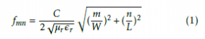
where C is the light velocity in free space, µr is the equivalent permeability and r is the equivalent permittivity. By selecting the feed location, the first two modes TM10 and TM11 can be excited in the study. We found that by increasing h, the resonant frequency shifts to low frequency and the bandwidth of low frequency band becomes narrow while the bandwidth of high frequency band becomes broad. The antenna geometry is shown in Figures 1 and 2. Detailed dimensions are listed in Table 1.
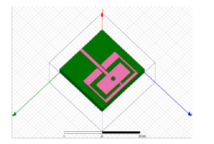
Figure 1: Proposed microstrip patch antenna.
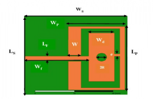
Figure 2: Design of the proposed microstrip patch antenna.
3. Simulation Results
The reflection coefficient is a parameter which is used to quantify how much of an electromagnetic wave is reflected back at antenna terminals in the transmission medium. An S11 value (cf. Eq. 2) is measured in dB and is negative, and expresses the ratio of reflected power (Pref ) to incident one (Pin) at port 1, if S11<-10 dB then 90% of power excited is transmitted.
Table 1: Proposed antenna parameters (mm).
| Parameters | Values (mm) |
| Patch length (Lp) | 30 |
| Patch width (Wp) | 22 |
| Feed width (Lf) | 2 |
| Feed length (Wf) | 25 |
| Ground length (Ls) | 40 |
| Ground width (Ws) | 40 |
| Height (h) | 1.6 |
| e | 1 |
| R | 0.75 |
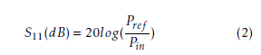
Figure 3 shows the result of the comparison study for different values of the parameter R. It is apparent from Figure 3 that, on the one hand, the widest frequency of multiband antenna is getting for R=0.75 mm and on the other hand, a very low return loss can be recorded at the frequency of 6.8 GHz. However, simulated results depict that a poor impedance matching in the upper Ultra Wideband range from 9.07-9.15 GHz and 10.02-10.5 GHz is obtained.
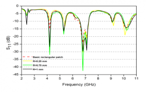
Figure 3: Return loss of proposed patch antenna for different values of R.
Figure 4 illustrates the performance of VSWR for the proposed microstrip patch antenna, which lies between 1 and 2 for all resonant frequencies with minimum reflected power which is inferior than -14 dB. The conclusion derived from the analysis of both Fig. 3 and 4, i.e., simulated results of return loss and VSWR respectively, confirms that the designed multiband patch antenna ensures obtaining good performance.
The simulation results of gain of the proposed microstrip patch antenna are shown in Figure 5. The results emerged from Figure 5 confirm the fact that the first 3 resonant frequencies, i.e., 4.1- 4.3 GHz, 5.21-
5.43 GHz and 6.55-7.25 GHz, are approximately omnidirectional pattern while the remaining ones, i.e., 7.027.15 GHz, 9.07-9.15 GHz and 10.02- 10.5 GHz. are directional pattern. Table 2 reports the obtained performances of bandwidth, return loss, VSWR and Gain, under several resonant frequencies.
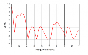
Figure 4: Simulated results of proposed patch antenna(R=0.75 mm): VSWR.
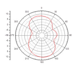
Figure 5: Gain of proposed patch antenna (R=0.75 mm).
Figure 6 shows the 3D radiation pattern for different resonance frequencies : (a) for 4.2 GHz, (b) for 5.3 GHz, (c) for 6.8 GHz, (d) for 7.1 GHz, (e) 9.1 GHz and
(f) for 10.2 GHz. As can be seen, simulated results show similar uni-directional radiation patterns and very low cross polarization level. At the six frequencies, the radiation pattern achieves the front-back ratio which is superior than 10 dB.
In order to further analyze the effectiveness of the proposed antenna design, the current distribution is also investigated. Figure 7 illustrates the current distribution simulated on the radiating element for different resonance frequencies : (a) for 4.2 GHz, (b) for 5.3 GHz, (c) for 6.8 GHz, (d) for 7.1 GHz, (e) for 9.1 GHz and (f) for 10.2 GHz. It is found that due to the insertion a circular hole inside the rectangular patch antenna and rectangular slots in the ground plane, surface current density is varied significantly. It is flowed an entire
Table 2: Bandwidth, Return loss, VSWR and Gain for various resonant frequencies.
|
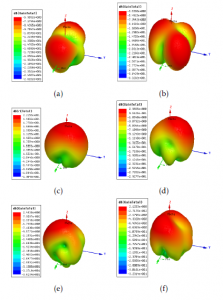
Figure 6: The radiation pattern in 3D of proposed patch antenna (R=0.75 mm) at (a) 4.2 GHz, (b) 5.3 GHz, (c) 6.8 GHz, (d) 7.1 GHz, (e) 9.1
patch at 4.20 GHz and 6.8 GHz. It also emerges that it mainly flows on feed line and notch cut of the patch antenna at 5.3 GHz, 7.1 GHz and 11.47 GHz. It flows on edge and feed line of the proposed patch antenna at 9.1 GHz and 10.2 GHz. In addition, it can be observed that the current density is more near the edge rectangular slot WxLp as illustrated in Fig. 7.(a) and (b), which exhibits the resonance at 4.2 and 5.3 GHz, respectively. At these frequencies, the current in the front patch is employed to adjust these resonances.
Near the microstrip line, higher current density is observed which is responsible for the resonance at 6.8 GHz and 7.1 GHz, respectively, as illustrated in Fig.
7.(c) and (d). The larger current path near the slots WxLp and microstrip line exhibit the resonance at 10.2 GHz, as depicted in Fig. 7.(e) and (f). Note that, the introduction of the circular hole inside a rectangular patch antenna modifies the surface current distribution of the proposed design, so that the total current length path increases, allowing the designed antenna to operates at 4.2 GHz, 5.3 GHz, 6.8 GHz, 7.1 GHz, 9.1 GHz and 10.2 GHz frequency bands respectively, as illustrated in Fig. 7.
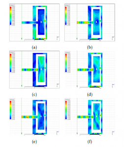
Figure 7: Simulated results of the surface current distribution for the antenna at (a) 4.2 GHz, (b) 5.3 GHz, (c) 6.8 GHz, (d) 7.1 GHz, (e) 9.1
4. Conclusion
In this work, we designed a new multiband microstrip patch antenna for wireless communication. The proposed antenna covers multiple frequencies (i.e., the frequency range between 2 GHz and 11 GHz). Simulation results showed that the return loss for all resonant frequencies is less than -14 dB and the proposed design achieves omnidirectional and bi-directional radiation pattern. Furthermore, the achieved peak gain is superior than 5 dB and the simulation results provide the better outcome for wireless communication.
- N. Prema, Anil kumar., “Design ofmultiband microstrip patch antenna for C and X band”, Optik 127 (2016) 88128818.
- Z.H. Li, Y.L. Xue, Z.Q. Deng, et al., “Study on optical switching effect of photonic crystals with negative effective index of refraction”, Optik 120 12(2009) 605609.
- K.Srivastava, A.Kumar, et al., “Multiband Integrated Wideband Antenna for Bluetooth/WLAN Applications”, International Journal of Electronics and Communications, S1434- 8411(18)30036-0.
- Ji-jun Wang, Zhi-pan Zhu, Yu-xin Sun, Ting-gen Shen, Lei-lei Gong, “Study on left-handed effect of composite helices and its application in square frame patch antennas”, Optik 124 (2013) 51895192.
- Chun-Xu Mao, Steven Gao et al., “A Novel Multiband Directional Antenna for Wireless Communications”, OI 10.1109/LAWP.2016.2628715, IEEE Antennas and Wireless Propagation Letters, 2016.
- Khalid Hati et al., “A Novel Multiband Patch Antenna Array for Satellite Application”, INTER-ENG 2016, 181(2017) 496 -502.
- T. Ali, M. Muzammil Khaleeq, R.C. Biradar, “A Multiband Reconfigurable slot antenna for Wireless Applications”, International Journal of Electronics and Communications (2017), doi: https://doi.org/10.1016/j.aeue.2017.11.033.
- T. Ali, Biradar R.C. “A compact multiband antenna using rectangular stub loaded with metamaterial for IEEE 802.11N and IEEE 802.16E”, Microw Opt Technol Lett 2017; 59(4):1000- 1006.
- Ting Wu, Xiao-Wei Shi, Ping Li, HaoBai. “Tri-band microstripfed monopole antenna with dual polarisation characteristics for WLAN and WiMAX applications”, Electron Lett 2013;49(25):1597-1598.
- JaswinderKaur, Rajesh Khanna. “Development of dual-band microstrip patch antenna for WLAN/MIMO/WIMAX/AMSAT/WAVE applications”, Microw Opt. TechnolLett2014;56(4):988-993.
- Shan Shan Huang, Jun Li, Jian Zhong Zhao. “Design of a compact triple-band monopole planar antenna for wlan/wimax applications”, Prog Electromagn Res C 2014; 48:29-35.
- M. Salehi, A. Tavakoli, “A novel low mutual coupling microstrip antenna array design using defected ground structure”, Int. J. Electron. Comm. 60 (10) (2006) 718723.
- F.Y. Zulkifli, E.T. Rahardjo, D. Hartanto, “Mutual coupling reduction using dumbbell defected ground structure formultiband microstrip antenna array”, Prog. Electromagn. Res. Lett. 13 (2010) 2940.
- M.S. Alam, M. Tariqul, H. Arshad, “Gain enhancement of a multiband resonator using defected ground surface on epoxy woven glass material”, Sci. World J. 6 (2014), 159468 8, http://dx.doi.org/10.1155/2014/159468.
- J. Pei, A.-G.Wang, S. Gao, W. Leng, “Miniaturized triple-band antenna with a defected ground plane for WLAN/WiMAX applications”, IEEE AntennasWireless Propag. Lett. 10 (2011) 298301.
- K. He, S. Gong, F. Gao, Low-profile wideband unidirectional patch antenna with improved feed structure, Electron. Lett. 51 (4) (2015) 317319.
- Youssef Rhazi et al., “Effect of Microstrip Antenna Feeding in the K-band”,International Journal of Engineering and Technology, 4(6): 515-522, 2013, ISSN 0975-4024.
- Verma, A. K. and Z. Rostamy, “Resonance frequency of uncovered and covered rectangular microstrip patch using modified Wolff model,” IEEE Trans. Microwave Theory Tech., 41, 109- 116, 1993.