A Comprehensive Review on the Feasibility and Challenges of Millimeter Wave in Emerging 5G Mobile Communication
 , Isdore Akwukwuegbu 1, Mathew Olubiwe 1, Chikezie Onyebuchi Nosiri 1, Atimati Ehinomen 1, Akande Akinyinka Olukunle 2, Samuel Okechukwu Okozi 2, Longinus Ezema 2, Benjamin Chukwujekwu Okeke 2
Adv. Sci. Technol. Eng. Syst. J. 4(3), 138–144 (2019);
 DOI: 10.25046/aj040318
This article presents a comprehensive review on the feasibility and challenges of millimeter wave in emerging fifth generation (5G) mobile communication. 5G, a multi-gigabit wireless network is the next generation wireless communication network. The mmWave cellular system which operates in the 30-300 GHz band has been proposed for use as the propagation channel. Its large bandwidth potential makes it a candidate for the next-generation wireless communication system which is believed to support data rates of multiple Gb/s. High frequency bands such as mmWave have channel impairments. These impairments are challenges that are necessary to be properly understood. Employing mmWave as a propagation channel requires dealing with these challenges which this paper is aimed at reviewing. One aim of the work is to discuss these challenges in a more elaborate manner using simple mathematical equations and graphics to ensure clarity. To achieve this, current related works were studied. Challenges and solutions are identified and discussed. Suggested research directions for future work are also presented. One is developing suitable electronic such as fast analog-to-digital (ADC) and digital-to-analog (DAC) systems necessary for the transmitter/receiver (TX/RX) system.
1. Introduction
The demand for high-speed reliable communications has always been on the increase. This demand has been a challenge to existing third generation (3G) wireless network as well as the fourth generation long term evolution – advance (4G LTE-A) which is the most current network. These ever increasing traffic demand, combined with significantly improved user experience have resulted to the drive towards the next generation 5G mobile communication networks due to its large capacity. It has been widely accepted that the capacity of the 5G wireless communication system will be able to handle 1000 times the capacity of the 4G (LTE-A) wireless communication [1]. The 5G network will therefore serve as a key enabler in meeting the continuously and ever increasing demands for future wireless applications.
It has also been the consensus that future 5G network should realize the goals of thousand-fold system capacity, hundredfold energy efficiency, ultra-high data rate, ultra wide radio coverage and an ultra-low latency [2], [3]. It is commonly assumed today that around the year 2020, a new 5G mobile network will be deployed [4]. The ability to have massive number of devices processed will be compulsory as there will be billions of connected devices in the 5G wireless communication network by 2020 [5]. This is because there will be an increase in the popularity of various intelligent or smart devices resulting to huge traffic demand.
The implementation of 5G has come with some concerns which have generated some interests. The provision of secure network infrastructure is one of such many areas of interest. In [6] methods of providing substantial security requirements were investigated. Spectral efficiency and energy efficiency requirements were investigated in [1]. Elsewhere in [7], the adoption of software defined network (SDN) in 5G as a platform to achieve efficient end-to-end (E2E) latency, authentication, hand over and privacy protection was studied. Interference challenges and mitigation techniques were extensively discussed in [8], [9].
System architecture is also an area of great interest. This is because a robust system architecture to enable Gbps user experience, seamless coverage, and green communications is a must for an aggressive 5G version [10]. This will be possible based on advanced technologies which are necessary for the above requirements to be practicable. These technologies will form the key elements of 5G wireless systems.
Some of these technologies have also gathered great interest and are seen as promising candidates for 5G wireless communication systems [11], [12]. One of such is the HetNet (heterogeneous network) technology. Described in [3], the HetNet creates a multi-tier topology where multiple nodes are deployed with dissimilar characteristics such as transmit power, coverage areas, and radio access technologies.
Other technologies discussed in several literature include millimeter wave (mmWave) techniques, denser small cells (DSC), software defined air interface (SDAI), and high-efficiency multiple antenna techniques known as massive multiple input multiple output (mMIMO) [13]-[15].The area that have appealed to many researchers is the mmWave and its application in the next generation mobile network.
Available sources in public domain have records of the application of mmWave technique in some specialized areas. Its use in Radio-over Fiber (ROF) technology was discussed in [16]. The discussion centered on the main mmWave signal generation technique for ROF technology. In [17], mmWave was presented as a technology that has to be supported by signal processing in mmWave wireless systems and some challenges that may be faced in doing so. The paper laid emphasis on using MIMO at higher carrier frequencies.
Another area of interest is its application in 5G mobile communication. The common view here is its ability to support larger bandwidth compared to microwave frequencies. This attractive feature of mmWave was discussed in [18] as well as the advantages and disadvantages of its application in 5G networks. In another study, extensive propagation measurements were carried out at 28GHz and 38 GHz to determine the path loss, delay spread and penetration characteristics [19]. The measurements made were to obtain results that could be useful in the design of future 5G mmWave communication systems. Here, like in other related work, mmWave applications were documented but the likely challenges especially its propagation characteristics were not well discussed.
Since mmWave has been proposed to drive the 5G mobile network, it is necessary to have sufficient knowledge of these challenges that must be addressed. This is because understanding the radio channel is a fundamental requirement to developing future mmWave mobile communication systems [19]. This paper is out to address the above by focusing on some of the several major challenges and possible solutions of mmWave as a proposed propagation medium for future 5G networks.
The novelty of this work is that, challenges of mmWave as a transmission medium were identified from several sources and discussed in a more simplified and elaborate manner. Mathematical expressions obtained from these sources were used to carry out computations which were not so in the original literature. The purpose for the computations is to help in proper understanding of the subject. To carry out this work, current related scholarly works were consulted.
The contributions of this paper are listed as follows:
- We identified and discussed in a simplified and elaborate manner the challenges and possible solutions for the implementation of mmWave for 5G mobile communication.
- Unlike other literature where similar issues were either mentioned or listed, this work presents itself as a one source where much information on the subject matter could be obtained.
- We suggested possible directions for future work based on the reviewed articles.
The rest of the paper is organized as follows: section II covers a discussion on mmWave, a brief comparison with microwave frequency and propagation problems. In section III, the solutions and suggestions for further investigations are presented. Section IV is the conclusion.
2. Millimeter Wave
Generally the radio spectrum for the millimeter wave (mmWave) is between 30 GHz to 300 GHz. This band of frequencies utilizes wavelengths between 1 and 10mm. In practice however the frequencies suitable for wireless communication are between 71-76 GHz and 81-86 GHz bands which are referred to as E-band or the 70GHz and 80GHz bands [20]. The 5 GHz spectrum available in each of these bands makes mmWave a propagation medium with ultimate bandwidth that can be compared only to fiber optic (FO). Aggressive deployment of FO by operators may be restricted due to geographical constraints and economic reasons. Millimeter wave technology presents itself as the next attractive alternative capable to overcome such constraints.
Its suitability for wireless backhaul, immunity to interference, high capacity and inexpensive nature are discussed in [2]. Millimeter wave frequencies present signals with small wavelengths. This characteristic makes it potentially suitable for the deployment of large number of antennas for signal directivity and link reliability improvement by compensating severe path loss to achieve larger coverage [21]. It has a potential Gigahertz transmission bandwidth incomparable to other microwave band used in conventional cellular networks [22].
Table 1: Comparison of millimeter wave and microwave frequencies
| Parameter | Millimeter wave Frequency | Microwave Frequency |
| Frequency band | 30GHz-300GHz | 300MHz-30GHzWave |
| Wavelength | 10mm-1mm | 1m-0.01m |
| Bandwidth | Ultrahigh | high |
| Antenna size/weight | Smaller due to very short wavelength | Large especially at the lower part of the band |
| Coverage | Suitable for short distance | Long distance application especially at 4-13 GHz band
(Long haul) |
| Frequency reuse option | Suitable for Frequency reuse | Frequency reuse will likely cause interference |
| System Gain | Very high gain (Gain is proportional to frequency) | High gain |
| Attenuation | High during heavy rainfall | Good resistance to rain at lower frequencies |
| Peak rate | 10-100 Gbps | 1-5 Gbps |
| Application | Radar, mmWave imaging, medicine, mmWave scanner | Radio and television broadcasting, cellular telephony, satellite and terrestrial communication, radar, navigation |
Although microwave which covers the band of frequency from 300MHz-300GHz has been widely used in wireless communication, the mmWave due to its higher frequency range has a greater prospect in terms of capacity delivery. Table 1 shows a brief comparison between mmWave and microwave frequencies. It is seen that based on their respective frequencies, mmWave has an advantage over microwave in bandwidth and antenna size. This two features have been accepted as very useful in the realization of 5G networks [13], [18].
2.1. Weather and Environmental Effects
(I) Propagation Losses
Other wireless technologies use microwave frequencies which have lower carrier frequencies compared to mmWave communication (Table 1). It is known that the higher the signal frequency the more likely it becomes susceptible to adverse atmospheric conditions. Therefore, in the GHz band of frequencies the atmosphere is seen as a propagation medium characterized with the presence of atmospheric constituents such as molecules, water vapor and suspended water droplets. Millimeter wave signals are absorbed by these atmospheric constituents. Also signals at GHz band suffer from rain attenuation. This is illustrated in Figures 1 and 2.
Figure 1 [23], shows the degree of attenuation suffered by frequencies between 1 to 1000 GHz band. At 75GHz in the E-band, it is observed that a mere rain drizzle results to 0.4dB loss and increases to about 30dB for a typical tropical rainfall. It is also shown that signal attenuation increases with rain intensity as depicted in Figure 2 [24]. At 200 mm/h of rain, 3GHz suffered 0.1dB loss as against 92dB loss for 30GHz. Details of mmWave signal attenuation are documented in [25] where experimental data obtained from both the rain intensity and rain attenuation measurements were statistically processed. Apart from rain attenuation, atmospheric absorption is also a major impediment to mmWave communications [26].
 Figure 1. Effect of rain attenuation on mmWave frequencies [23]
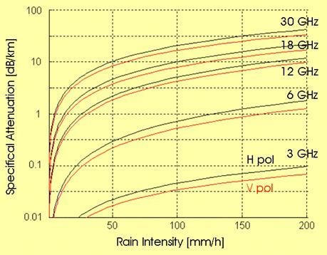 Figure 2. Rain attenuation vs frequency [24]
The rain attenuation and atmospheric absorption characteristics of mmWave propagation limit the range of mmWave communications [23], [27].
The propagation characteristics of mmWave communications in different bands are summarized in [23]. They showed the level of loss due to both rain attenuation and oxygen absorption under line-of-sight (LOS) and non-line-of-sight (NLOS) channels. Table 2 presents a summary of signal loss due to oxygen absorption at 200m range. It is observed that the propagation losses at 28GHz and 38GHz are not as significant as those of 60GHz and 73GHz.
Table 2: Absorption loss in mmWave frequencies [23]
| Frequency Band (GHz) | Range (m) | Oxygen Absorption (dB) |
| 28 GHz | 200 | 0.04 dB |
| 38 GHz | 200 | 0.03 dB |
| 60 GHz | 200 | 3.2 dB |
| 73 GHz | 200 | 0.09 Db |
(II) Free Space Loss
Due to its nature, mmWave frequencies experience greater free space loss than lower frequencies. In [28], the Free Space Loss (FSL) is shown to be inversely proportional to the square of the operating wavelength, ie
![]() Here, in Km, is the link distance between transmit and receive antennas and λ the wavelength of the operating frequency. In decibel form and after converting to units of frequency, the equation can be expressed as [28]
Here, in Km, is the link distance between transmit and receive antennas and λ the wavelength of the operating frequency. In decibel form and after converting to units of frequency, the equation can be expressed as [28]
![]() Where is the frequency in GHz.
Where is the frequency in GHz.
Computed FSL in the E-band using (2) is tabulated in Table 3. The Table indicates a proportional increase in FSL with both frequency and distance. In particular, it indicates that for a given frequency the FSL increases with distance. Thus, the more the distance or range the higher the signal attenuation.
Table 3. Free space loss at mmWave frequencies
| E-Band (GHz) | FSL (dB) | ||||
| R=1m | R=2Km | R=3Km | R=4Km | R=5Km | |
| 71 | 129.4 | 135.4 | 139 | 141.5 | 143.4 |
| 72 | 129.5 | 135.6 | 139.1 | 141.6 | 143.5 |
| 73 | 129.7 | 135.7 | 139.2 | 141.7 | 143.6 |
| 74 | 129.8 | 135.8 | 139.3 | 141.8 | 143.8 |
| 75 | 129.9 | 135.9 | 139.4 | 141.9 | 143.9 |
| 76 | 130.0 | 136.0 | 139.6 | 142.0 | 144.0 |
(III) Foliage Loss
Foliage loss takes into account the effect of vegetation within the propagation environment such as tree size and nature or roughness of plant leaves. As the leaves become comparable in size relative to the wavelength, there is decrease in signal penetration through the leaves, while scattering off the leaves increases. [29].
Work in [28], showed an empirical relationship that can be used to predict or determine foliage losses. This was developed by CCIR Rpt 236-2 which reported that for a depth of less than 400m, the loss is given by
![]() Here, f is the frequency in MHz and covers the range 200-95,000MHz (0.2-95GHz). R is the foliage depth in meters (R< 400 m).
Here, f is the frequency in MHz and covers the range 200-95,000MHz (0.2-95GHz). R is the foliage depth in meters (R< 400 m).
Using (3), the foliage loss for the E-band was computed and tabulated in Table 4. For a range of 300m the loss at 70GHz is 174dB which increased to 177dB at 75GHz. Similar computation in [28] indicated that at 40 GHz, a penetration of 10m taken to be equivalent of a large tree or two in tandem, the foliage loss is about 19 dB. These values show that foliage loss in mmWave is significant enough and like other forms of losses should not be neglected in overall network design.
Table 4: Foliage loss at mmWave frequencies
| E-Band (GHz) | F (dB) | ||
| R=100m | R=200m | R=300m | |
| 70 | 90.06 | 136.51 | 174.11 |
| 71 | 90.45 | 137.10 | 174.86 |
| 72 | 90.83 | 137.67 | 175.59 |
| 73 | 91.20 | 138.24 | 176.32 |
| 74 | 91.58 | 138.81 | 177.04 |
| 75 | 91.95 | 139.37 | 177.78 |
(IV) Blockage Loss
Blockage in communication is caused by obstructions in the path of propagation which are man-made or natural physical structures. Such obstructions introduce losses which cannot be neglected. With a small wavelength, links in the 60 GHz band are sensitive to blockage by obstacles (e.g., humans and furniture) [23]. For example, blockage by a human penalizes the link budget by 20-30 dB [23][30]. This was also confirmed in [31] where it was shown that mmWave systems suffer from significant loss in performance due to blockages caused by humans or other obstacles along its propagation path.
(V) Penetration Loss
This loss arises as transmitted frequencies attempt to propagate through objects along its path. At mmWave frequencies the losses are more significant compared to UHF/microwave bands. Current works contained in most literature on this subject covers outdoor-to-outdoor and outdoor-to-indoor penetration loss measurements. More importantly is the outdoor-to-indoor measurements. A 28GHz outdoor-to-indoor measurements made and recorded in [32][33] were done using a rotating horn antenna channel sounder which can provide an accurate absolute delay information. The result indicated clusters, larger excess delays and larger angular spreads indoor.
Another work on 28GHz is described in [34] while [35] investigated the penetration loss for the band of 0.8GHz to 28GHz. Measurements described in [34][36][37] and[38] for both outdoor and indoor environments are summarized in Table 5.
Table 5: Summary of mmWave penetration losses
| Ref | Frequency (GHz) | Material Type/Environment | Loss (dB) |
| [29] | 28 | Outdoor-indoor | 3-60 |
| [31] | 38 | Tinted glass
Glass door |
25.0
37.0 |
| [32]
[33] |
28 | Tinted glass(Outdoor)
Brick pillar(Outdoor) Clear glass (Indoor) Dry wall (Indoor) |
40.1
28.3 3.6 6.8 |
The Table shows penetration losses for common materials found in buildings. By observation, outdoor materials recorded higher penetration losses than indoor materials.
2.2. Hardware Implementation Challenges
Apart from atmospheric losses there are other challenges resulting from the type of hardware that can suitably and efficiently function at the mmWave frequencies. With high carrier frequency and wide bandwidth, there are several technical challenges in the design of circuit components and antennas for mmWave communications [23], [39]. Highlighted in [2], are the cost of electronic components and the complexity of transceiver including high-speed analog-digital converters (ADCs), digital analog converters (DACs), synthesizers, mixers, etc., which are much larger than that in conventional microwave communications.
In [37], the nonlinear distortion of power amplifiers (PA) especially at 60GHz was discussed as an impediment to the implementation of mmWave. Also in [40], [41], phase noise and IQ imbalance are seen too as challenging problems faced by radio frequency integrated circuits (RFIC).
3. Solutions and Suggested Areas for Further Investigations.
3.1. Solutions
The shortcomings of millimeter wave in terms of propagation and system hardware implementation have been discussed. Despite these challenges, its large bandwidth makes the usage of mmWave communications in the 5G cellular access still attractive [42]. Some remedial steps are necessary for the practical realization of mmWave systems.
(I) Short Distance Communication (SDC)
In mmWave, path loss increases with distance as earlier shown. Its limited range makes it suitable for short distance applications. This gives room for the shrinking of cells which is an effective way to increase area spectral efficiency [43], [44]. Small cells are base stations (BS) that cover a small geographical area and are meant for low power, short range wireless communication. Cell size shrinking reduces the number of users per cell, thus more spectrum is made available to each user. The small cell sizes and short distances will improve frequency reuse [2]. Frequency reuse is a cellular concept which allows the use of same radio frequencies on BS within a geographical area. These BS are separated by sufficient distances to avoid or minimize signal interference with each cell.
(II) Reduced Inter cell Interference
Attenuation due to rain, foliage and atmospheric absorption has been discussed as major impediments or challenges to mmWave application. Deployment of small cells known as ultra dense cell (UDC) can help overcome such problems. This is because atmospheric absorption will efficiently increase the isolation of each cell by further attenuating or reducing the background interference from other distant base stations [23], [26], [45]. Densification of small cells has been proposed in [46], [47] as a technique to achieve increase in network capacity in the future and in [23], as the promising solution for the capacity enhancement in the 5G cellular networks.
(III) Hardware solution
Work in overcoming the technical challenges associated with electronic components of mmWave is ongoing and have been discussed in several research reports. Progress work on radiofrequency (RF) power amplifiers (PAs), low-noise amplifiers (LNAs), voltage-controlled oscillators (VCOs), etc., are documented in [39]. Radio frequency integrated circuits and other low-cost electronic components are believed to bring about the evolution of massively broadband 5G millimeter wave communications [39], [44]. Recorded in [48] are efforts made in providing a practical phased array antenna solution.
3.2. Suggested Areas for Further Investigation
Challenges of mmWave have been highlighted. Propagation loss is a major impediment in its practical implementation. A solution to this is to improve in antenna technology. This will result in the use of greater gain antennas. Beam steerable antenna technologies have the capability for such gains. The workings of such antennas are fully described in [49], [50]. These are antennas that have the ability to compensate the path loss caused by blockage from dynamic obstacles.
Since mmWave is associated with small wavelength and the size of an antenna greatly relates to the operating wavelength, large number of antennas or MIMO technology can also be made use of in mmWave communications. An example is the Massive MIMO (mMIMO) antennas widely discussed in [51]-[53]. This is also known as large-scale antenna systems (LSAS) [51], hyper-MIMO (HMIMO), or full-dimension MIMO systems [54].
This technology which allows the BS to be equipped with up to a hundred or more antennas is meant to leverage on the benefits of the traditional MIMO antenna system known for its ability to significantly improve the capacity and reliability of wireless systems [51] [55]. The challenges defined for mmWave can be tackled with the implementation of massive MIMO which theoretically promises increase in spectral and energy efficiencies [56]. It is believed that the antenna gain will be high enough to overcome high propagation loss in mmWave bands,
However, further development is required to make this concept practically functional. This is because a large antenna structure such as massive MIMO will have individual array elements each with active transceiver modules.
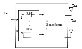 Figure 3.Transmit antennas with dedicated RF chains
That is each transmitter (TX) and receiver (RX) will have a dedicated RF chain (RFC) as shown in Figure 3. For massive MIMO with a hundred or more antennas it will result to high system cost as well as increase in system complexity.
Therefore, further work in developing low cost, low profile and appropriate electronic components is necessary. Examples of such electronic components are high-speed analog-to-digital and digital-to-analog converters (ADC/DAC), RF amplifiers, TX/RX switches, filters, etc. for each individual antenna element [57]. The direction here should be in hardware unit design that will reduce overall system complexity and cost.
Methods of solving large outdoor-to-indoor penetration loss caused by certain building materials (Table 5) is also another direction for further work.
4. Conclusion
Millimeter wave band of frequencies with ultimate bandwidth has been discussed as a potential candidate for 5G mobile communication. Key challenges in propagating at this frequency band as well as some hardware issues have also been discussed. The implementation of mmWave in the emerging 5G wireless communication will have to address these shortcomings. To this end some solutions have been suggested. Based on the study and since the mmWave 5G wireless communication is an emerging network still at its early stage of implementation, some selected areas for further work have also been suggested.
Conflict of Interest
The authors declare no conflict of interest.
- C. X. Wang, S. Wu, L. Bai, X. You, J. Wang and I. Chih-Lin, “Recent advances and future challenges for massive MIMO channel measurements and models,” Special Focus on 5G Wireless Communication Networks, 59, 1-16, 2016, Doi: 10.1007/s11432-015-5517-1).
- Z. Gao, L. Dai, D. Mi, Z. Wang, M. Ali Imran, and M. Z. Shakir, “MmWave massive MIMO based wireless backhaul for 5G ultra-dense network,” arXiv:1508.03940v3 [cs.IT], 1-7, 2015
- N. Yang, L. Wang, G. Geraci, M. Elkashlan, J.Yuan and M. Di Renzo, “Safeguarding 5G wireless communication networks using physical layer security,” IEEE Communications Magazine, 20-27, 2015, DOI:10.1109/MCOM.2015.7081071.
- V. Jungnickel, K. Manolakis, W. Zirwas, B. Panzner, V. Braun, M. Lossow, M. Sternad, R. Apelfröjd and T. Svensson, “The Role of Small Cells, Coordinated Multipoint and Massive MIMO in 5G,” IEEE Communications Magazine, 2014
- E. Dahlman, G. Mildh, S. Parkvall, J. Peisa, J Sachs and Y. Selen, “5G radio access,” Ericsson Review, 6(1), 2014
- P. Schneider, “5G Security research at Nokia Bell Labs,” Nokia Solutions and Networks, 2016.
- B. Uma and S. Sumathi, “High throughput, privacy and security for handover in 5G networks using software-defined networking,” International Journal of Innovative Research in Science, Engineering and Technology, 5(2), 2016
- A.K. Mishra and S. Gaur (2016), “Review of the pilot contamination problem for massive MIMO and possible solution,” International Journal Of Engineering Sciences & Research Technology, 5(7), 2016
- N. Mehrotra and A. K. Chaubey, “Pilot contamination effect in massive MIMO and analysis of mitigation techniques,” International Journal of New Technology and Research, 3(2), 19-23, 2017.
- C.-L. I, C. Rowell, S. Han, Z. Xu, G. Li, and Z. Pan, “Toward green and soft: A 5G perspective,” IEEE Commun. Mag., 52(2), 66- 73, 2014.
- E. G. Larsson, F. Tufvesson, O. Edfors, and T. L. Marzetta, “Massive MIMO for next generation wireless systems,” IEEE Commun. Mag., 52(2), 186-195, 2014.
- H. Quoc, N. Linköping, “Massive MIMO: Fundamentals and system designs,” Linköping Studies in Science and Technology Dissertations, (1642), 2015
- R. Taori and A. Sridharan, “Point-to-multipoint in-band mmWave backhaul for 5G networks,” IEEE Wireless Commun.53 (1), 195-201, 2015
- Q. Sun, C. Lin, S. Han, Z. Xu and Z. Pan, “Software defined air interface: a framework of 5G air interface,” IEEE Wireless Comm. 2015. DOI: 10.1109/WCNCW.2015.7122520
- E. G. Larsson, O. Edfors, F. Tufvesson and T..L.Marzetta, “Massive MIMO for next generation wireless system,” IEEE Comm magazine 52(2), 186-195, 2014. DOI: 10.1109/MCOM.2014.6736761
- D. Singh and P. Singh, “Techniques of millimeter-wave signal generation in ROF system: A Review,” International Journal of Computer Applications and Information Technology,1(2), 45-49, 2012
- R .W. Health Jr, N.Gonzalez-Prelcic, S.Rangan, W.Roh and A.Sayeed, “An overview of signal processing techniques for millimeter wave MIMO systems,” Computer Science Information Theory, 2015
- D.D.Pai, “Survey on millimeter wave mobile communication for 5G cellular networks,” International Journal of Innovative Research in Electrical, Electronic, Instrumentation and Control Engineering, 5(6), 278-284, 2017
- T.S. Rappaport, S. Sun, R. Mayzus, H. Zhao, Y. Azar, K. Wang, G . N. Wong, J.K. Schulz, M. Samimi and F. Gutierrez, “Millimeter wave mobile communication for 5G cellular: It will work,” IEEE access, 1, 335-349, 2013
- P. Adhikari, “Understanding millimeter wave wireless communication,” Loea Corporation, 1-6, 2008,
- S. Han, C.-L. I, Z. Xu and C. Rowell, “Large-scale antenna systems with hybrid precoding analog and digital beamforming for millimeter wave 5G,” IEEE Commun. Mag., 53(1), 186-194, 2015.
- L. Wei, R. Q. Hu, Y. Qian and G. Wu, “Key elements to enable millimeter wave communications for 5G wireless systems,” IEEE Wireless Commun., 21(6), 136-143, 2014
- Y. Niu, Y. Li, D. Jin, L. Su and A. V. Vasilakos,“A Survey of millimeter wave (mmWave) communications for 5G: opportunities and challenges,” GrXiv: 502.07228v1 [cs.NI], 1-17, 2015
- “E-band technology” 2012. [Online]. Available www.e-band.com
- G. Timms, V. Kvičera and M.Grábner, “60 GHz band propagation Experiments on terrestrial paths in Sydney and Praha,”Radio Engineering, 4(4), 2005.
- F. Al-Ogaili and R.M. Shubair, “Millimeter wave mobile communications for 5G: challenges and opportunities,”2016. DOI:10.1109/APS.2016.7696210.
- Q. Zhao and J. Li, “Rain attenuation in millimeter wave ranges,” in IEEE Int. Symp. Antennas, Propag. EM Theory,1-4, 2006
- “Millimeter wave propagation: Spectrum Management Implications,” Federal Communications Commission, 1997
- M. Shafi, J. Zhang, H. Tataria, A. F. Molisch, S.Sun, T. S. Rappaport, F. Tufvesson, S.Wu, and K. Kitao, “Microwave vs. millimeter-wave propagation channels: key differences and impact on 5G cellular systems,” IEEE Communications Magazine, 2018. DOI:10.1109/MCOM.2018.1800255
- S. Singh, F. Ziliotto, U. Madhow, E. M. Belding and M. Rodwell, “Blockage and directivity in 60 GHz wireless personal area networks: from cross-layer model to multihop MAC design,” IEEE J. Sel. Areas Commun., 27(8),1400– 1413,2009.
- A. Samuylov, M. Gapeyenko, D. Moltchanov, M. Gerasimenko, S.Singh, N. Himayat, S.Andereev, Y. Koucheryavy, “Characterizing spatial correlation of blockage statistics in urban mmWave systems,” Globecom Workshop (GC Wkshps), IEEE, 1-7, 2016. DOI: 10.1109/GLOCOMW.2016.7848859
- C. U. Bas, R. Wang1, T. Choi, S. Hur, K. Whang, J. Park, J. Zhang and A. F. Molisch, “Outdoor to indoor penetration loss at 28 GHz for fixed wireless access,” arXiv:1711.0168v1 [cs.IT], 2017.
- J. Ko, K. Lee, Y. J. Cho, S. Oh, S. Hur, N. G. Kang, J. Park, D. J. Park, and D. H. Cho, “Feasibility study and spatial-temporal characteristics analysis for 28 GHz outdoor wireless channel modelling, IET Communications, 10(17), 2352–2362, 2016.
- C. Larsson, F. Harrysson, B. E. Olsson, and J. E. Berg, “An outdoor-to- Indoor propagation scenario at 28 GHz,” in 8th European Conference on Antennas and Propagation (EuCAP), 3301–3304, 2014.
- I. Rodriguez, H. C. Nguyen, I. Z. Kovcs, T. B. Srensen, and P. Mogensen, “An empirical outdoor-to-indoor path loss model from below 6 GHz to cmwave frequency bands,” IEEE Antennas and Wireless Propagation Letters, 16, 1329–1332, 2017
- I.R. Larrad, H.C. Nguyen, T.B. Sorensen, J.A. Holn, J.Elling, P. Mogensen and B.Vejlgaard, “Analysis of 38 GHz mmwave propagation characteristics of urban scenarios,” in 21th European Wireless Conference; 1-8, 2015.
- T. S. Rappaport, S.Sun, R. Mayzus, H. Zhao, Y,Azar,K. Wang,G.N. Wong, J.K. Schulz, M. Samimi and F.Gutierrez “Millimeter wave mobile communications for 5G Cellular: It Will Work! “IEEE Access, 1, 335–349, 2013. DOI: 10.1109/ACCESS.2013.2260813
- H. Zhao, R. Mayzus, S. Sun, M. Samimi, J.K. Schulz, Y.Azar, K.Wang, G.N Wong, F. Gutierrez and T.S. Rappaprt , “,” in IEEE ICC, 5163–5167, 2013. DOI: 10.1109/ICC.2013.6655403
- T. S. Rappaport, J. N. Murdock, and F. Gutierrez, “State of the art in 60- GHz integrated circuits and systems for wireless communications,” in IEEE, 99(8), 2011, 1390– 1436, 2011
- S. K. Yong, P. Xia, and A. Valdes-Garcia, 60GHz Technology for Gbps WLAN and WPAN. Chichester, United Kingdom: John Wiley & Sons Ltd., 2011.
- B. Razavi, “Design considerations for direct-conversion receivers,” IEEE Trans. on Circuits and Systems II, 44,(6), 428–435, 1997.
- S. Rangan, T.S. Rappaport, and E. Erkip, “Millimeter wave cellular wireless networks: potentials and challenges,” in IEEE, 102(3), 2014, 366–385, 2014
- J. G. Andrews, S. Buzzi, W. Choi, S.V. Hanly,A.Lozano, A.C.K. Song and J.C. Zhang, “What will 5G be?” IEEE Journal on Selected Areas in Communications, 32(6), 1065–1082, 2014. DOI: 10.1109/JSAC.2014.2328098
- T. S. Rappaport, Y. Xing, G. R. MacCartney, Jr., A. F. Molisch, E. Mellios, and J. Zhang, “Overview of millimeter wave communications for fifth- generation (5G) wireless networks-with a focus on propagation models,” IEEE Transactions on Antennas and Propagation, Special Issue on 5G, 2017.
- A. Gupta and R. K. Jha, “A survey of 5G network: architecture and emerging technologies,” Access, IEEE, 3, 1206–1232, 2015.
- A. Ghosh, T. A. Thomas, M. C. Cudak, R. Ratasuk, P. Moorut, F. W. Vook, T. S. Rappaport, G. R. MacCartney, S. Sun, and S. Nie, “Millimeter wave enhanced local area systems: A high-data-rate approach for future wireless networks,” IEEE Journal on selected areas in communications, 32(6), 1152– 1163, 2014.
- R. Baldemair, T. Irnich, K. Balachandran, E. Dahlman, G. Mildh, Y. Seln, S. Parkvall, M. Meyer, and A. Osseiran, “Ultra-dense networks in millimeter- wave frequencies,” IEEE Communications Magazine, 53(1), 202– 208, 2015.
- W. Hong, K. -H. Baek, Y. Lee, Y. Kim, and S. T. Ko, “Study and prototyping of practically large-scale mmWave antenna systems for 5G Cellular Devices,” IEEE Communications Magazine, 52(9),63–69, 2014.
- M. K. Samimi and T. S. Rappaport, “3-D millimeter-wave statistical channel model for 5G wireless system design,” IEEE Transactions on Microwave Theory and Techniques, 64(7), 2207–2225, 2016
- S. Sun, G. R. MacCartney, Jr., and T. S. Rappaport, “A novel millimeter- wave channel simulator and applications for 5G wireless communications,” in IEEE International Conference on Communication (ICC),1-7, 2017.
- L. Lu, G. Ye Li, A. Lee Swindlehurst, A. Ashikhmin, and R. Zhang, “An overview of massive MIMO: benefits and challenges,” IEEE Journal of Selected Topics in Signal Processing, 8(5), 2014.
- S. Dierks_, W. Zirwas, M. J¨ager, B. Panzner, and G. Kramer, “MIMO and massive MIMO – analysis for a local area scenario,” in 23rd European Signal Processing (EUSIPCO)
- J. Hoydis, S. T. Brink and M. Debbah, “Massive MIMO in the UL/DL of cellular networks: How many antennas do we need?” IEEE Journal on Selected Areas in Communications, Institute of Electrical and Electronics Engineers, 31(2), 160 – 171, 2013
- C. K Agubor, M. C. Ndinechi, G. A. Chukwudebe and F. K. Opara, “Performance evaluation of multiple antenna systems with diversity techniques using BER analysis,” Academic Research International, 5(5) 2014
- S. Malkowsky, J. Vieira, L. Liu, P. Harris, K. Nieman, N. Kundargi, I. Wong, F. Tufvesson, V.O. Wall and O. Edfors, “The world’s first real-time testbed for massive MIMO: Design, implementation, and validation,” arXiv:1701.01161v2 [cs.IT], 2017.
- Panzner, W. Zirwas, S. Dierks, M. Lauridsen, P. Mogensen, K. Pajukoski and D. Miao, “Deployment and implementation strategies for massive MIMO in 5G. in Proc. Globecom Workshops (GC Wkshps), 346-351, 2015, DOI:10.1109/GLOCOMW.2014.7063455