Transfer Function Analysis of Fractional-Order Three-Dimensional Electrically Coupled Cell Network

Adv. Sci. Technol. Eng. Syst. J. 4(3), 145–149 (2019);
 DOI: 10.25046/aj040319
1. Introduction
Due to the use of electrical and non-electrical systems for modeling, in recent years circuit networks have become more attractive [1,2]. A study on the resistance network of the graphene showing the presence of a planar circuit network in nature received the Nobel Prize in Physics in 2010 [3-5]. In the last few decades, researchers have published publications on fixed-coefficient circuit networks. These publications focus on the analysis of circuit networks consisting of single-member resistors and capacities with constant coefficients [6,7].
The fractional order mathematical models developed for inductances and capacities have more accurate electrical characteristics for the better realization and best fit. Especially actual inductors and capacitors are in fractional order elements in nature [8]. In recent years, some researchers have been working on the realization and design of fractional elements [9-11]. In addition, in recent years, researchers have focused on fractional order theory [12 -15]. However, few researchers have dealt with the issue of electrical characteristics of multidimensional circuit networks. Therefore, we focus on the equivalent network impedance and transfer function of the three-dimensional cell networks in the fractional domain.
Recently, some researches concentrate on the fractional-order three-dimensional circuit network [16]. Moreover, there has been little research on the transfer function and input equivalent impedance characteristics of the three-dimensional circuit network in the fractional order sense with different cases. That is why, we concentrate on the electrical characteristics of the fractional-order three- dimension network, which may lay the bases for both the electric circuits and dielectrics communities [17].
This study is organized as follows: Basic definitions of the fractional order capacitors and inductors are introduced in Section 2. Also the general expressions of the transfer function and equivalent input impedances of the circuit-network are derived by using the nodal analysis method. MATLAB and PSPICE simulations of the fractional order three- dimensional network are done and simulation results is given in Section 3. Finally the paper is concluded in the last section.
2. Fractional-Order Three Dimensional Circuit Network Model
Electrical networks consisting of one-dimensional and two-dimensional RC elements mentioned in the literature have been proposed and used. Since there are no fractional elements in these electrical networks, the models have been insufficient to precisely characterize the system. RLC elements are used in electrical equivalent circuits in one-dimensional and two-dimensional networks used in the dynamic analysis of electrical interactive cells [18]. Three dimensional random RC networks have been proposed for modeling electrical circuits and dielectric material communities [19]. Nodal-matrix analysis was used to model the three-dimensional network of dispersed capacitance and resistance elements for the multiple bound layers [20]. This article shows that large three-dimensional RC networks can be modeled in terms of performance using fractional order models and integrals. In the fractional domain, the fractional order 2 × n RLC circuit network model has been proposed to examine the impedance characteristics of the circuit network [21]. Electrical RC equivalent circuits are proposed to examine the behavior of the human body impedance against contact currents in a wide frequency range. With the proposed fractional-order three-dimensional RLC networks, expressions for calculating the typical equivalent impedances of the network using the differential equation model and the matrix transform method for different cases in the fractional domain are derived [22].
The circuit diagram of fractional-order three-dimensional electric circuit network used in this study is given in Figure 1.
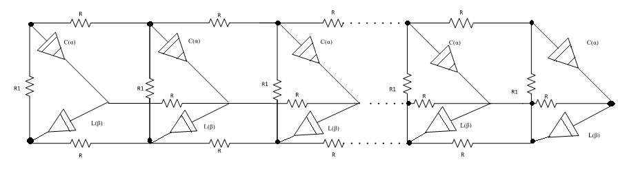 Figure 1: RLC circuit network diagram
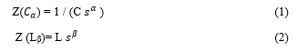
In general, this circuit network is obtained by combining three one-dimensional circuit networks. There are n cells in the network. The electrical coupling between the cells is indicated by the resistances R. The cells were modeled with resistance (R1), fractional- order inductance (Lß) and capacities (Cα). Fractional impedance values of capacitance and inductance are
given below respectively.
 Fractional-order three-dimensional cell network is modelled with lumped parameters passive elements such as resistance, fractional-order inductance and capacitance. Thus, this network is composed of passive elements and is a passive network.
In calculating the characteristic values of the circuit network, such as transfer function and the equivalent impedance, the well-known node voltages analysis in circuit theory is used in the fractional domain. For the circuit network depicted in Fig. 1, the equation of the node voltages in matrix form in the fractional domain is written as
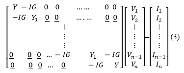 Here, the I1 (3 × 1) indicates the source currents connected to the nodes and the Vi (3 × 1) indicates the node voltages. Vi = [Va, Vb, Vc]t shows the node voltages for each cell, where a,b,c nodes are terminals of abc triangle, I (3 × 3) unit matrix, G = 1 / R is resistance conductivity. Elements of the node admittance matrix are;
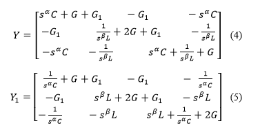 From (3) and (4) and (5) ones can obtain (6) in the matrix form.
![]() The node A (3n × 3n) in size is the admittance matrix and is in the form of a symmetric band matrix. It illustrates the vector of the Vd (3n × 1) node voltages vector and I (3n × 1) dimension of the node voltages vector and I (3n × 1) the current vector. If the vector of the node voltages is resolved from the equation (6),
The node A (3n × 3n) in size is the admittance matrix and is in the form of a symmetric band matrix. It illustrates the vector of the Vd (3n × 1) node voltages vector and I (3n × 1) dimension of the node voltages vector and I (3n × 1) the current vector. If the vector of the node voltages is resolved from the equation (6),
![]() is obtained. When a single source is applied to the network, the equivalent driving point impedances and transfer functions for various situations can be found from equation (7) by using the basic definition.
is obtained. When a single source is applied to the network, the equivalent driving point impedances and transfer functions for various situations can be found from equation (7) by using the basic definition.
3. Computer Simulations
The element and parameter values selected for the circuit network shown in Figure 1; are given as follows. The cell number is taken as n=5 in all computer simulations. The element values are chosen as R1= 1Ω, R= 0.1 Ω, L= 1 H and C = 1 F.
3.1. MATLAB Simulations
A constant current source I1 is applied to the Va node and is taken as Va = V1. If V1 input voltage is written in terms of node voltages, V1= [100 000 000 000 000].Vd . The equivalent impedance is calculated as Z = V1 The equivalent impedance is calculated as Z = V1. For fractional order terms, the second order approach was obtained using the value of s0.5s = (5s2 + 10s + 1) / (s2 + 10s + 5), Z equivalent input impedance of the network was obtained as a rational function in s [23]. The frequency response, step response and impulse response are obtained from Z network impedance function obtained as a rational function. Then MATLAB simulation results for these rational functions are shown in Figure 2, Figure 3, Figure 4, respectively.
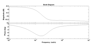 Figure 2: Frequency responses for network input impedance
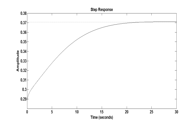 Figure 3: Step response of the input impedance
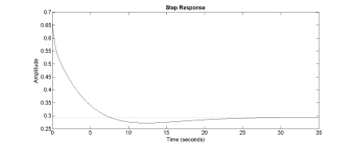 Figure 4: Impulse response of the network impedance
Let the output voltage Vo get the input voltage V1 when the circuit network is excited by a source. The input voltage is V1= [100 000 000 000 000] .Vd and the output voltage is Vo= [000 000 000 000 001]. Vd. The transfer function (as voltage gain) is defined as TF = Vo / V1. For fractional order terms, TF is also obtained as a rational function of the TF using the quadratic fractional approach in [24]. The frequency response, step response and impulse response obtained by MATLAB simulations of TF are depicted in Figure 5, Figure 6, Figure 7, respectively.
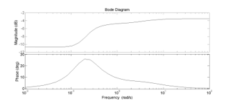 Figure 5: The transfer function frequency responses
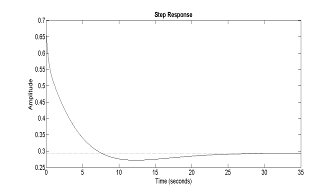 Figure 6: The transfer function step response
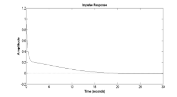 Figure 7: The transfer function impulse response
3.2. PSPICE Simulations
The experimental realization of the study was done by PSPICE program using element values taken before in the MATLAB simulations. Developed SPICE model of the network circuit for n=5 cell is presented in Figure 8.
In PSPICE simulations, the quadratic approximation equivalent circuits given in [24] are used instead of fractional capacitor and inductance elements, and the simulation results are depicted in Figure 9, Figure 10, Figure 11, Figure 12, respectively.
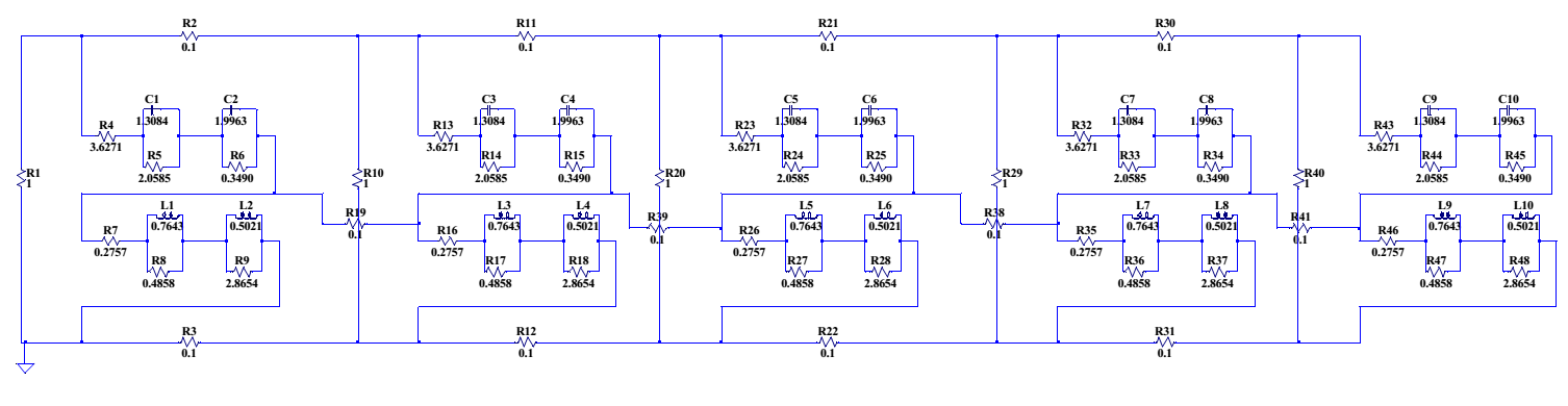 Figure 8: PSPICE model of the cellular network for n=5 cell
 Figure 9: Frequency response of network transfer function with PSPICE
 Figure 10: Step response of network transfer function with PSPICE
 Figure 11: Impulse response for the network transfer function with PSPICE
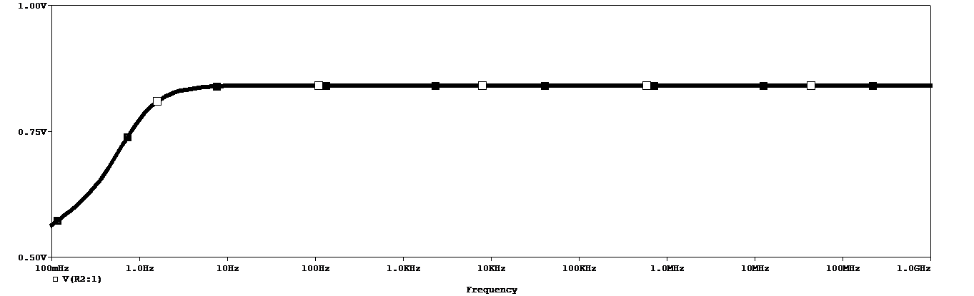 Figure 12: Frequency response of equivalent network impedance with PSPICE
4. Conclusions
In this paper, mathematical models were introduced for the analysis of the fractional-order three-dimensional network in fractional domain. The transfer function and the equivalent input impedance of the fractional-order three-dimensional network were obtained in form of a rational transfer function using rational function approximation for each fractional term. Although the circuit network includes nonlinear fractal elements such as fractional-order capacitors and inductors transfer function approximation method was offered by means of some advanced properties of Laplace transform. A new mathematical method was developed to model and analyze fractional- order three- dimensional circuit network in the fractional domain.
In general, the electrical characteristics of the three-dimensional cellular circuit network were investigated in the fractional domain. Using the nodal analysis method which is well known in circuit theory first transfer function and equivalent input impedance of the fractional order three dimensional circuit network were derived in fractional domain. After that employing second order approach for each fractional order term, equivalent input impedance and transfer function were found as a rational function in s. As a consequence of this process we could be able to calculate transfer function and equivalent input impedance of the network as a rational transfer function.
The electrical system characteristics of the transfer function and the driving point impedance of the fractional- order three–dimensional circuit network were investigated by using MATLAB simulation programs in detail. Moreover network system characteristics such as impulse, frequency, and step responses were graphically obtained for both transfer function and equivalent input impedance. Dynamic characteristics and stability of fractional –order three –dimensional circuit network were also examined with respect to model parameters such as inductance, capacitance, resistances, fractional order values and cell numbers. In order to compare MATLAB and PSPICE simulations the same network parameter values were employed in all simulations. Finally, when PSPICE and MATLAB simulation results are compared graphically, basic similarities between PSPICE and MATLAB simulation results were observed.
- Von Busse V., Swartz S.M., and C.C, ’’Flight metobolism in relation to speed in Chiroptera: Testing the U-shape paradigm in short-tailed fruit bat Carollia perspicillata,’’ Exp.Bio., 216(11), s. 2073-2080, 2013.
- Simpson R., Jaques A., Nunez, C.H. Ramirez, and Almonacid A., ’’Fractional calculus as a mathematical tool to improve the modelling of mass transfer phenomena in food,’’ Food Eng.Rev., 5(1) s. 45-55, 2013.
- Bolotin K.I., Ghahari , Shulman M.D., Stormer H.L., and Kim p., ’’Observation of fractional quantum Hall effect in graphene ,’’ Nature, 475(7), s. 7354-7358, 2011.
- Feldman B.E., Krauss B., Smet J.H., and Yacoby A., “Unconventional sequence of fractional quantum hall states in suspended graphene,’’ Science, 337 (6099), s. 1196-1199, 2012.
- Owaidat M.Q., Hijjawi R.S., and Khalifeh J.M., “Network with two extra interstitial resistor,” J.Theor. Phys., vol. 10, s. 3152-3159, 2012.
- Yao N.Y., Gorshkov A.V., Laumann R., Lauchli , J. Ye, and Lukin M.D., “Realizing fractional Chern insulators in dipolar spin systems,’’ Phys .Rev.Lett., 110(18), 2013.
- Hijjawi R.S., Assad J.H., and Sakaji, H.J., “Perturbation of an infinite network of identical capacitors,’’ J. Mod. Phys., vol. B2, s. 199-209, 2007.
- Carlson G., and Halijaj C., “Approximation of fractional capacitors(1/s)1/n by regular Newton process,’’ IEEE T. Circuit System, s. 210-213, 1964.
- Tenreiro M.J.A., and Galhano A.M.S.F., “Fractional order inductive phenomena based on the skin effect,’’ Nonlinear Dyn., vol. 1-2, s. 107115, 2012.
- Radwan A.G., and Salama K.N., “Passive and active elements using fractional Lβ,Cα,’’ IEEE T. Circuits-1, vol. 10, s. 2388-2397, 2011.
- Das S., Sivaramakrishna M., Biswas K., and Goswami B., “Performance study of a constant phase angle based impedance sensor to detect milk adultcration. Sensors and actuators,’’ A-Physical, vol. 2, s. 73-278, 2011.
- Krishna M.S., Biswas K., and Goswami B., “Fabrication of a fractional order capacitor with desired specifications; A study on process identification and characterization,’’ IEEE Trans.Electron Dev., vol. 11, s. 4067-4073, 2011.
- Haba T., Ablart G., Camps T., Olivie F., “Influence of the electrical parameters on the input impedance of a fractal structure reaslised on silicon,’’ Chaos Solitons Fract., vol. 2, s. 479, 2005.
- Elshurafa A.M., Almadhoun M.N., Salama K.N., and Alshareet H.N., “Microscale electrostatic fractional capacitors using reduced graphene oxide percolated polymer compasites,’’ Phys.Lett., vol. 23, s. 1234-1237, 2013.
- Radwan A.G., and Salama K.N., “Fractional–order RC and RL circuit,’’ Circuits System Signal Process, vol. 6, s. 1901-19015, 2012.
- Doghri, T.Djerafi, A. Ghotto, and K.Wu, “Substrate integrated wave guide directional couplers for compact three-dimentional integrated circuitsş” IEEE Trans. Microw. Theory Tech., Vol.63, No.1, pp. 209-219, Jan. 2015
- R, K, H. Galvao, S. Hadjloucas, K.H. Kienitz, H. M. Paiva, and R.J. M: Afonso,”Fractional order modeling of large three-dimentional RC networks,” IEEE Trans. Circuits Syst. I, Reg. Papers, Vol.60, no.3, pp.624-637 , 2013
- Chen P., and He S.B., “Analysis of the fractional order paralle tank circuit,’’ Circuit System. Comput., vo. 6, s. 452-458, 2013.
- Merichel M.B., Eyman E.D., and Katar S.B., “Analysis of a Network of Electrically coupled neorans producing Rhytmic Activity in the snail helisoma trivolvis,” IEEE Trans on Biomedical Engineering, BMM-24, no. 3, s. 277-287, May.1977.
- Torre, W.G. Owen, G. Sandini, “The Dynamics of electrically interacting cell,” IEEE Trans on Systems, Man and Cybernetics, vol. 13, no. 5, s. 757-765, September/October 1983.
- Zhou, D. Chen , Herbert H., C. Lu, “Fractional order 2×n RLC Circuit Network,” Journal.f Circuit Systems and Computers, vol. 24, no. 9, DOI.10.1142/5021812661550142X(25 pages), 2015.
- J. Freeborn, A.S. Elwakil, B. Macendy, “Compact wide frequency range fractional order models of human body impedance against contact current,” Hindawi Publishing Corporation, Mathcmatical Problems in Engineering, vol. 2016, Article ID. 4567937.
- Tanudar, S. Kumar, “Analysis &Design of Fractance based fractional order filter,” Int Journal of Innovative Research in Electrical,” Electronics, Instrumentation and Control Engineering, vol. 1, Issue. 3, June 2013.
- Radwan A. G. And Salama K. N.,”Fractional-order RC and RL circuit”, Circuits Sys. Signal Process, Vol:6, 1901-1915, 2012.