Modeling of Grid-Connected Photovoltaic System Installation in Moroccan Ibn Tofail University

Adv. Sci. Technol. Eng. Syst. J. 4(3), 150–155 (2019);
 DOI: 10.25046/aj040320
The main importance of solar photovoltaic energies research is to meet the many environmental demands of the energy challenge, to maximize power and to reduce the costs of photovoltaic (PV) systems to reply the energy needs of population. In the present research work, the first objective is to study the performance and the output energy can be produced by a photovoltaic panel installed in the parking of Ibn Tofail University at Kenitra – Morocco. These provide the basis for developing a simple and efficient model for the PV panel electrical behavior. As the output powers of photovoltaic system are influenced of the solar irradiances (G) and cell temperature (T); the effects of varying the two variable factors, series and shunt resistances, and partial shading on the output of the PV system are presented. Then, the PV system is connected to three phases grid using Boost converter controlled by the perturb and observe technique of Maximum Power Point Tracking and using the DC-AC inverter. The Matlab/Simulink software is used to model the system and to show the simulations result.
1. Introduction
Up to date it is known that, the renewable energies must be developed, so that it can meet the energy needs which are in ascending order continuously [1]. The use of these green energies sources plays a very important role in keeping the planet clean as possible of pollution [1]. Specially, the application of solar PV energy has increasing in different fields [2]. Morocco intends to exploit this clean and inexhaustible energy on a massive scale over the next ten years (Raphaëlle Grouix-Monvoisin, CIFE, 2015). In this work, a PV system installed in the parking of the Ibn Tofail University in Morocco was chosen, to study its performance and to make the system as competitive as possible. So, the objective of this work is to present a design of a boost converter controlled by perturb and observe method of MPPT to extract the maximum power whatever the variations of sunshine. To do this, the work is divided in four parts. The first part describes the modeling of the photovoltaic system consists of a photovoltaic generator, boost converter and MPPT controller. The second one describes the modeling of the PV grid-connected system; this section is divided into two steps; the first is a boost converter controlled by MPPT which allows the PV system to operate in its best condition. The second step is a DC-AC converter that allows a connection to the grid [3]. The output current has to be sinusoidal and in phase with the grid voltage. The boost converter and the inverter operate independently to facilitate the system control [4]. The third part of this work gives the results of the simulations. Last section presents and discusses the results.
2. Methodologies
In this section of this search work, the different components of the system studied are presented and modeled. The figure bellow shows the block diagram of the proposed system
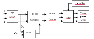 Figure 1: Block diagram of the proposed system
2.1. Photovoltaic panel model
A PV module is PV cells connected in parallel, which are defined by a p-n junction in a film semiconductor that produce electricity from solar radiation [1].
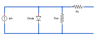 Figure 2: Equivalent circuit of PV panel with single diode
The Kirchhoff’s law is applied to get the equation below:
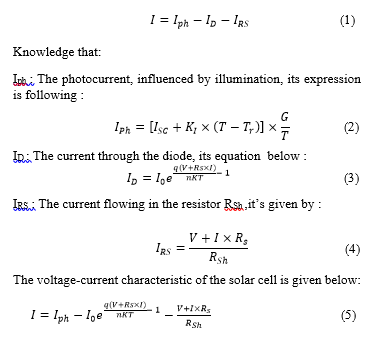 The voltage-current characteristic of the solar cell is given below:And knowledge that:
I0 : The dark saturation current, influenced by temperature.
ISC: The current short circuit
q : The charge of an electron is equal to 1.6 × 10⁻¹⁹ C.
K : The constant of Boltzmann is equal to 1.38. 10−23J/K.
T : The ambient temperature, in Kelvin.
RS : Cell series resistance
RSh : The cell (shunt) resistance
G : The illumination in W/m2.
VCO: Open circuit voltage (I=0).
In this paper, PV panels installed in the parking of Ibn Tofail University in Morocco were studied based on the electrical characteristics values shown in the table 1; their reference is Jinko JKM280M-60-DV.
Table 1: Values of electrical characteristics of panel used
| Electrical characteristics | Values |
| STC(Standard Test Conditions) Power Rating | 280 W |
| PTC Power Rating | 302.21 W-1 |
| STC Power | 15.8 W/ft2(170.2W/m2) |
| Peak Efficiency | 17.02% |
| Power Tolerance | 0% /+3% |
| Number of cells | 60 |
| Nominal Voltage | Not applicable |
| Imp | 8.81A |
| Vmp | 31.8V |
| Isc | 9.49A |
| VOC | 38.6V |
| NOCT | 45°C |
The PV panel was modeled in Matlab/Simulink software using the values of the electrical characteristics presented in the table 1, with the previous equations at Standard Test Conditions (STC), when illumination is equal to G= 1000 W/m2 at temperature T=25°C.
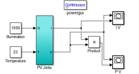 Figure 3: The model of PV panel in Matlab/Simulink
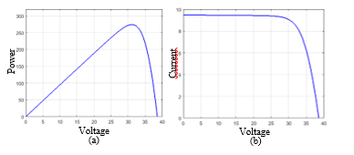 Figure 4: Power-voltage and power-current waveforms of photovoltaic generator; (a) power-voltage waveform of photovoltaic module at STC conditions; (b) current-voltage waveform at STC conditions
In this part of work, the current produced by the cell is almost proportional to the illumination G. But, the voltage V across the junction varies because it is a function of the potential difference at the NP junction of the material itself [5]. However, the open circuit voltage decreases only with irradiation. As a result, the optimum power of the cell is almost proportional to the illumination and its point is at approximately the same voltage of different values of irradiation [6]. The output powers of PV system are influenced of the solar irradiances and cell temperature [7]; and, the effects of varying the two variable factors are presented in the figure 4.
2.2. Influence of illumination and temperature
To treat these important parameters, the simulations on the figure 5 are done to obtain the current-voltage and power voltage curves of the PV field for different values of illuminations and temperatures.
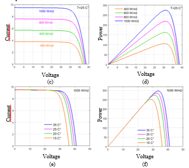 Figure 5: (c) Current-Voltage waveform of a Photovoltaic panel by changing illumination (d) Power-Voltage waveform of a Photovoltaic panel by changing Illumination; (e) Current-Voltage waveform of a Photovoltaic panel at different values of temperature; (f) Power-Voltage waveform of a Photovoltaic panel at different values of temperature
It is noticed that, by changing the illumination, it is observed that when G = 400 W/m2, 600 W/m2, 800 W/m2 and 1000 W/m2, the respective maximum powers of the PV field are 105 W, 165 W, 220 W and 280 W. The maximum power of the PV field increases with sunshine respectively. It is even for the current that believes with illumination.
With changing the temperature, and G=1000 W/m2 ; it is observed that when T = 15 ° C, 20 ° C, 25° C and 35 ° C the maximum voltages of the PV field are respectively 36 V, 38 V, 39 V and 41 V, and the respective maximum powers are 250 W, 270 W, 280 W and 300 W. Then, the tension decreases as the temperature increases. It’s the same for power maximum that decreases with temperature. We notice that the maximum power of the PV panel at STC conditions is equal 280 W which is compatible with the maximum power PMPP [8].
2.3. Boost converter model
A BOOST converter is a DC to DC voltage converter;
that converts a DC voltage into another DC voltage from lower to higher value [1-9]. The figure 6 shows the model and components of the converter used.
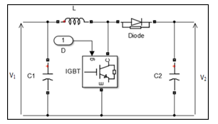 Figure 6: The circuit of DC-DC converter modeled in Matlab/Simulink
This converter operates according to the following equations.
The mathematical expression between V1 and V2 is following [1]:
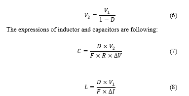 Knowledge that:
F: Frequency
D: Duty cycle
R: Load resistance
2.4. Maximum Power Point Tracking
It is known that, the Maximum Power Point Tracking (MPPT) is a technique to search and find the optimum maximum power that can deliver an electrical generator; its principle is based on the automatic variation of duty cycle continuously to maximize the power. There are different methods of MPPT, the most known in the literature are: perturb & observe incremental conductance, fractional open circuit voltage, fractional short circuit current, fuzzy logic and artificial neural network. In this paper, the perturb and observe technique of MPPT was applied. The principle of this method is to perturb by decreasing or increasing the cyclic ratio α and to observe the effect on the power delivered by the photovoltaic generator [10]. Its algorithm is shown in the figure 7.
 Figure 7: The perturb & observe algorithm
 Figure 8 : The model of P&O MPPT in Matlab/Simulink
2.5. Inverter
The principal challenge of PV system connected to grid is to have compatibility between PV arrays and the electricity grid [11]. The inverter converts the direct current of the output of PV array into a synchronizes sinusoidal waveform. The creation of a sinusoid from a DC voltage is obtained through voltage pulses of specific width. This technology uses the Pulse Width Modulation or Pulse width Modulation [12]. The objective of the inverter is converting a DC voltage similar to that of a battery into a single-phase or three-phase alternating voltage similar to that of the electricity grid [13]. It consists of a set of active components (electronic switches) and passive components (transformer) [9]. In this paper three-phase and three level voltage source converters has been used to convert DC power into AC. Three-phase converter symbol is following:
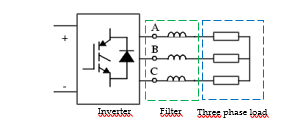 Figure 9: The three-phase inverter proposed
To control the Voltage inverter and reduce harmonics, several switching techniques are used; Pulse width modulation (PWM) technique is the best of these techniques, to produce a sinusoidal variable voltage to the load [14]. It is controlled in closed loop with a PI regulator [15-17].
3. Results
After modeling of the different blocks of the grid-connected photovoltaic system, the figure 10 presents the block diagram of the global model in matlab/Simulink.
 Figure 10: The global model of the system in Matlab/Simulink
This section presents the results of simulations using the STC conditions; the temperature is set at 15°C and illumination is set at 1000 W/m2.
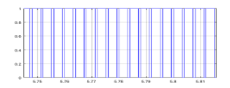 Figure 11: The curve of duty cycle
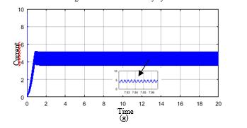


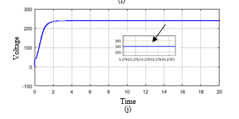 Figure 12: The curves of current and voltage; (g) the current of photovoltaic system before MPPT; (h) the current after MPPT; (i) Voltage before application of Boost converter; (j) Voltage after boosting with the converter
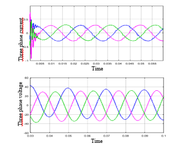 Figure 13: The output of voltage and current with filter
4. Discussions
In this section of the present research work and as shown by the figure 11; the duty cycle is varied using perturb and observe technique of MPPT to generate the best value of voltage for attaining the maximum power.
Then, the figures 12 shows the outputs of voltage and current before application of BOOST converter controlled by MPPT controller; that the voltage was equal to 33.48 V DC; and after boosting, its value was increased from that value 33.48 V DC to 239.7 V DC. That’s the objective of applying the DC-DC converter and MPPT controller. Also, it’s clearly to see the amelioration of curves without steady-state oscillations.
For the three-phase current and voltage, it is noticed that the figure 13 presents the output of DC current inverted into a synchronized sinusoidal waveform. That’s the objective of applying the DC-AC converter (Inverter).
In the present search work, it is observed that, the simulation results of the proposed system are encouraging and as expected, they meet the requirements of the studied system.
In the future, according to these results, the plan is to improve the work by the use of other controllers based MPPT or the combination of two controllers for better performance.
5. Conclusion
This paper presents a study and modeling of photovoltaic system connected to grid by the boost converter (DC-DC converter) controlled by the MPPT controller, to increase, raise the voltage and extract the maximum power point in different variations of irradiation and temperature; and a DC-AC inverter to inverts the continue output current generated by the PV arrays into a synchronizes sinusoidal waveform. The inverter used in this research study is PWM. To search for the maximum power point; Perturb and Observe based MPPT is the technique used in the present paper. The simulation results of the system studied in this paper are encouraging compared to the results obtained in literature. Therefore, in that case our system may be really recommended for practical application in larger electricity generation projects.
- Maroua Bouksaim, Nissrine Krami, Yassin Acci, Mohamed Nabil Srifi, Abdelkader Hadjouja.”Modeling of photovoltaic module using maximum power point tracking controller”, in 2018 IEEE International Symposium on Advanced Electrical and Communication Technologies (ISAECT), 2018.
- Zainal, Nurul Afiqah, Ajisman, and Ahmad Razlan Yusoff. “Modeling of photovoltaic module using matlab simulink”, IOP Conference Series Materials Science and Engineering, 2016.
- Fadil,H.E.,F.Giri, and J.M. Guerrero.”Grid-connected of photovoltaic module using nonlinear control”, 2012 3rd IEEE International Symposium on Power Electronics for Distributed Generation Systems (PEDG), 2012.
- H. El Fadil, F.Giri. “MPPT and utility power factor achievement in grid-connected PV System Using Nonlinear control”, IFAC Proceedings Volumes, 2012.
- P.Moraitis, “Review of the Operational Performance of Grid Connected PV Systems”, Master’s Thesis, Utrecht University, Utrecht, the Netherlands, 2014.
- Mau, S.; Jahn, U. “Performance analysis of grid-connected PV systems”. In Proceedings of the European Photovoltaic Solar Energy Conference and Exhibition (EU PVSEC), Dresden, Germany, 4–9 September 2006; pp. 2676–2680.
- Mahammad, Abd Kadir, Sharifah Saon, and Wong Swee Chee. “Development of optimum controller based on MPPT for photovoltaic system during shading condition”, Procedia Engineering, 2013.
- “Proceeding of the 1st International Conference on Electronic Engineering and Renewable Energy”, Springer Nature America,Inc,2019
- Zainuri, M.A.A.M.; Radzi, M.A.M.; Soh, A.C.; Rahim, N.A. “Development of adaptive perturb and observe-fuzzy control maximum power point tracking for photovoltaic boost DC–DC converter”. IET Renew. Power Gener. 2013, 8, 183–194.
- Saad Motahhir; Abdelaziz El Ghzizal; Aziz Derouich. “Modélisation et commande d’un panneau photovoltaïque dans l’environnement PSIM” ,2ème Edition du congrès international de génie industriel et management de système, CIGIMS’15,2015.
- Antonio Carlos Zambroni de Souza, Miguel Castilla Editors, “Microgrids design and implementation”, Cham, Switzerland : Springer, 2019.
- Lecture Notes in Electrical Engineering; 2015.
- Ghazanfar Shahgholian, Jawad Faiz, Pegah Shafaghi. “Nonlinear control techniques in uninterruptible power supply inverter: A Review”, 2009 Second International Conference on Computer and Electrical Engineering, 2009
- Nazmul Islam Raju, Md. Shahinur Islam, Ahmed Ahsan Uddin. “Sinusoidal PWM signal generation technique for three phase voltage source inverter with analog circuit & simulation of PWM inverter for standalone load & micro-grid system”, INTERNATIONAL JOURNAL of RENEWABLE ENERGY RESEARCH, 2013.
- Ramos-Paja, C.; Gonzalez, D.; Carrejo, C. “Predictive control of a photovoltaic dc/dc converter”. In Proceedings of the 6th IET International Conference on Power Electronics, Machines and Drives (PEMD2012), Bristol, UK, 2012; pp. 1–6.
- Titri, S.; Larbes, C.; Toumi, K.Y.; Benatchba, K. “A new MPPT controller based on the Ant colony optimization algorithm for photovoltaic systems under partial shading conditions”. Appl. Soft Comput. 2017, 58, 465–479.
- S. Z. Hassan, H. Li, T. Kamal, J. Ahmad, M. H. Riaz, M. A.Khan, “Performance of Different MPPT Control Techniques for Photovoltaic Systems” in 5th International Conference on Electrical Engineering, Pakistan 2018; pp 1-6.