Multi-Band Hand of God Antenna with Functionality Variation with Use of Slots and Feed Position

Adv. Sci. Technol. Eng. Syst. J. 4(3), 227–234 (2019);
 DOI: 10.25046/aj040330
This article investigates different versions of a new multi-band micro-strip antenna design. NASA inspired the antenna design from “Hand of God” galaxy discovery. A multi-band operation between 0.15 and 8 [GHz] is obtained and captures up to 10 frequency bands. The antenna has a small area of 4 x 5 cm2 and is printed on 1.6 mm epoxy-FR4 substrate. Adding slots and changing the feed position, led to different designs and increase in multi-band operation. Moreover, varactors are mounted on antenna surface, which resulted in frequencies as low as 50 MHz and as high as 8 GHz when. S11 simulations results were successfully compared with measured ones. Applications include different mobile generations, TV and different IoT systems.
1. Introduction
Multi-band antennas capture various segments of the frequency spectrum simultaneously. Yet, a challenging aspect of maintaing the required gain appears [1-6]. Of course, an antenna should have high efficiency to be able to capture many frequencies. Moreover, new technology requires smaller front end devices, and hence antenna size follows. Moreoever, selected frequencies are targetted, to cope with licenced frequency bands. Hence, research is still developing in this area.
Multiple frequency operation has become recently desired to engage IoT applications in same device. It allows performing technologies that require and or scan wide range of frequencies. For example, it is desirable to work with two mobile generations simultaneously [7]. Adapting to wearable technologies, [8], presented a relatively large antenna operating for different applications with up to six frequency bands. Alternatively, different bands related to same generation can be combined in same antenna [9]. Moreover, switches were mounted to achieve multiple resonances, while changing the switching scenario changes operation band being the L or S band [10,11]. Metamaterials were also exploited in [12] for multi-band operation.
The need to minimize space occupied by modern devices such as phones or sensors renders multi-band antennas more attractive since they replace many antennas [10], while still consistently frequencies in MHz range are mainly emitted by large antennas that are quarter wavelength, i.e. more than 12 cm in length and width [4,11,13,14]. This creates a challenge if high frequency ratio is targeted within same antenna. supporting different active parts of wireless spectrum.

Figure 1: Galaxy named ‘Hand of God’ by NASA
This paper suggests a novel design that covers multiple low and high communications frequency bands, serves IoT applications, and maintains a compact size. The design is inspired by a photo of a galaxy captured recently by NASA, entitled ‘Hand of God’ [15]. Hence, this antenna duplicates a cosmic shape using electromagnetic radiation modelling, in an articulate way. Ultimately, the antenna presented here, resonates at frequencies near 0.1 [GHz] up to 8 [GHz], knowing that different techniques are used to enhance these aspects.
 Figure 2: Equivalent circuit of slot loaded antenna
First, as power input position is varied, operating frequencies shifted. Hence, position of feed is an important parameter that is thoroughly investigated in the paper. Second, slots were easily incorporated in the design and enhanced increase of frequency operation in addition to bandwidth ratio. Third, varactors are added across slots to study their effect on frequency reconfigurability. As a result, frequency is tuned in the MHz range and resonance at 100 MHz is achieved, in spite of the very small physical length of the antenna.
The design of multiple extensions given by a hand shape is elaborated in this paper, since naturally each frequency is linked to a radiating element. Yet, the operation bands obtained outnumber the dipole, finger like extensions.
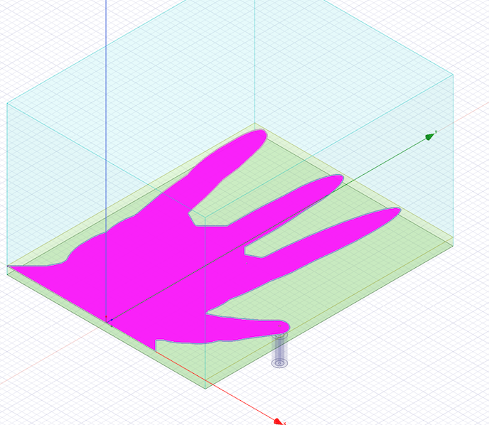
Figure 3: Simulated feed at 1st fingertip
The antenna has compact volume of 4 x 5 x 0.16 cm3, a new design that succeeds in combining more than six bands and captures ten bands in one specific scenario, with high frequency ratio of 53 starting at 0.15 [GHz], if no diodes are used. Frequencies above 8 [GHz] were not included in this research. 3G, 4G and IoT frequency applications are still main concern in antenna design. Authors present the ‘Hand of God’ for the first time, novelty is achieved in design, size and range of application [16]. In following sections, the antenna design significance is shown FEM modeling in HFSS. Third section shows the simulations results for feed through one chosen position. Section Four details all interesting scenarios in feeding positions and displays a comparison in S11 (return loss) results between measurements and simulations for the various fabricated prototypes. In section five, the effect of mounting varactors while DC voltage control is applied is shown. Sections six and seven show the current density and the corresponding radiation patterns for the resonant frequencies relative to the first discussed prototype.
2. Antenna Design Methodology
Due the importance of monopole, L and U shaped antennas in microstrip antenna design, the hand design holds importance in relation of design and shape. As the first draft of the patch design had shown multiple band characteristic, parametric sweeps that modify the shape for better resonance were done in FEM software tool HFSS. In fact, there is a conjecture that physical shapes in nature cope well with a certain frequency, and these shapes manifest certain cosmic frequencies, which is literally a direct link between shape and frequency. In fact, both ends of physics and metaphysics meet at the antenna design platform.
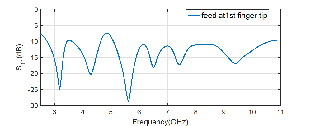 Figure 4: S11 simulated results of feed at 1st fingertip in Figure 3.
Moreover, the effective relation between having multiple extensions from a basic feed to a multiple frequency operation has immediately inspired me to recreate the hand shape on the patch after seeing the NASA photographs of a far galaxy. Yet, the use of FEM calculation tool for antenna design has facilitated turning the antenna conceptual design into an operating one. Here, experience in antenna design and persistence in using the HFSS software to explore all parametric influences on their own or in relation to other parameters has led to good results and even unexpectedly 9 resonant bands when slots were used.
The ‘Hand of God’ [15], is source of inspiration of this design due to the photo captured by NASA telescope. The finger shapes and hand is a renovated form of dipole antenna array, with main ‘palm’ space acting as a relatively large capacitance that stabilizes antenna radiation operation at large frequencies in GHz range. This is no the first time a cosmic/natural shape is successfully exploited in electromagnetics, examples include the spiral shape (inspired from a galaxy [17]) and many others showing the beauty of science in relation to nature.
The antenna with four fingers combines inductive and capacitive effect of each extension. Yet, it forms a new way of combining four dipole antenna extensions in a compact design. These were responsible for multiple frequency operation. In particular, each element has different length and shape, and spaces between elements play crucial role in minimizing destructive interference, since targeted frequencies have wavelengths comparable to antenna size. After performing many simulations on common area in the patch and length of the extensions, final design was achieved as shown in Figure 3. Initial setting of the model was even varied in total area and substrate material, but a double-sided FR4 substrate was most successful. Finally, small area of 4 x 5 cm 2 accommodated the multiple ‘finger like’ extensions to achieve the targeted multi-band operation.
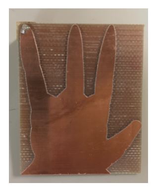
Figure 5: First feed scenario prototype at 4th fingertip.
Slots are used to increase bandwidth. Loading the radiating patch with slots or stub elements can extend bandwidth of the patch antenna. Additionally, varying the dimension of cutting slots on different locations and adjusting the shape of the slots like rectangular, circular, octagonal, fractal, and modified/partial ground plane, can help to obtain the desired bandwidth at estimated resonant frequency [18]. Slots are also used in size miniaturization of antenna [19] and increasing number of resonant frequencies [20].
 Figure 6: Comparison of S11 obtained in measurements and simulations results for 4th prototype (Figure 5).
Slot impedance is considered as series inductance and parallel capacitance, which adds to the total inductance and capacitance as shown in Figure 2, [21]. In fact, slots helped increase the number of resonant frequency bands over [0.1-8] GHz to nine with tunability over frequency range [0.2-0.8] GHz, and total area = 4 x 5 cm 2. In a similar approach, [22] has used 3 slots to achieve three resonant bands tunable at 3 frequencies over [0.6-2.7] GHz, and an area = 5 x 10 cm2. Slots with modes controlling method were used in [23]. Starting with a monopole at 0.25 λ then adding an open slot at 0.25 λ then a tuning pad, resulted in 2 bands [0.8-1.02] GHz and [1.69-2.73] GHz, knowing that the area = 10 x 6 cm2. Multiple slits on a rectangular patch were also used in [20], to achieve 4 bands over [5.8-7.87] GHz and antenna area of 2.6 x 7.75 cm2. Other methods can be listed here with corresponding characteristics, for example using multiport and theory of characteristic modes (TCM) to isolate frequency bands, resulting in 3 bands over [0.8-2.2] GHz [24]. In comparison, [25] mounted a 3D loop folded antenna (volume 60×5×5 mm3 ) on 100×60×0.8 mm3 FR4 substrate with full ground plane, for a mobile handset, to design a 3 bands tunable antenna over [0.8-2.5] GHz. Consequently, the present method is better improved over other methods due to carving the slots on the antenna patch along the extended finger shapes, which enhanced the resonant characteristic modes by doubling the mode effect being a result of splitting into two arms in a U shape.
3. Simulations basic design and effect of feed position
The antenna is a microstrip patch, with full ground, an area of 4 x 5 cm 2 and 1.6 mm thick epoxy FR4 substrate. The dimensions of finger shapes (see Figure 5) are 25.8 mm x 6 mm for 4th finger, 19.6 x 6 mm for 3rd finger , 21.5 mm x 6 mm for 2nd finger , 14 mm x 9.5 mm for 1st finger. The antenna feed is a coaxial cable as shown in Figure 3, where axes x, y, and z are in red, green, and blue respectively for later reference. In fabrication, an SMA connects the cable to the antenna at the variable positions to be discussed, where 50-Ω matching is considered.
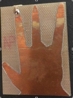 Figure 7: Antenna prototype with the feed at the 2nd fingertip.
The design is modeled in FEM software, HFSS. In order to preserve the universal shape, and improve results and easily accommodate the shape in small area for better performance, simulations were the main guide to refine the design, where there is no imperial formula to apply in this case. The underlying design is an overlap of geometrical shapes like polygons, ellipses, circles, and lines in coherence with basics of drawing depicted from human anatomy. The area being restricted to 4×5 cm2 has less extension of the wrist, which has shown no effect on multi-band aspect.
Feeding has been tested over 10’s of potential positions. Yet, resonance was easily achieved when the coaxial feed is placed the fingers tips. For example, an ultra-wide band (121% bandwidth) between 2.7 and 11 [GHz] is obtained when the feed is at the tip of the first finger as shown in Figure 4. The results at the remaining fingertips are shown in comparison with measurements.
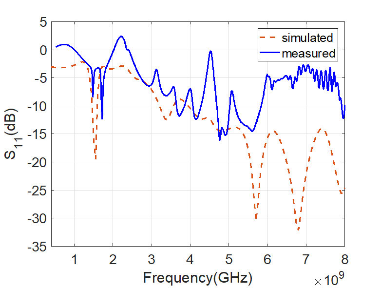 Figure 8: Comparison of S11 obtained in measurements and simulations results for 2nd prototype (Figure 7).
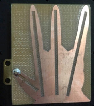 Figure 9: Antenna prototype with slots with the feed at the 1st fingertip.
4. Comparison between measurements and simulations results
First prototype, no slots and the power input at the fourth fingertip (Figure 5) :
The first prototype of feeding position at 4th fingertip is shown in Figure 5. It is fabricated as first test of the antenna simulations results. The reflection coefficient S11 is measure using a network analyzer that spams up to 8.5 [GHz].
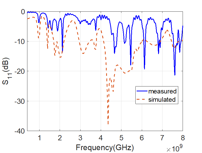 Figure 10: Comparison of S11 obtained in measurements and simulations results for prototype in Figure 9.
S11 results recorded in measurements coincide very well with simulated ones as shown in Figure 6. When comparing the resonance frequencies for the simulated and fabricated cases, small drift was obtained; i.e., (1,66, 1.74), (2.43, 2.34), (3.95, 4), (5.2, 5.06), (6.15, 6.42), and (7.2, 7.4) [GHz]. 0.27 [GHz] is the maximum difference between measured and simulated results due to many reasons, which include:
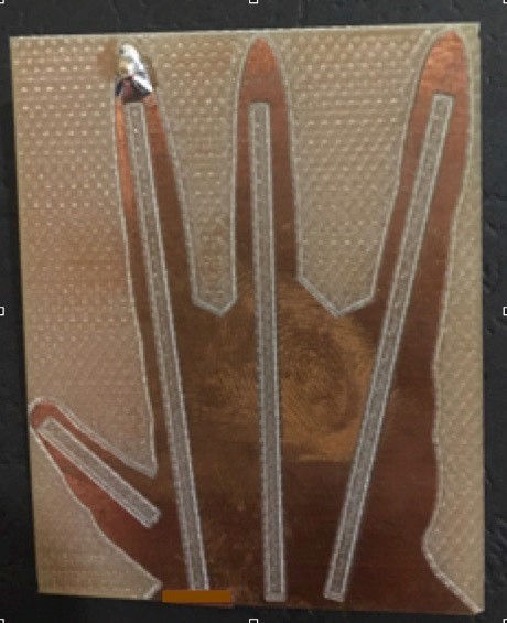 Figure 11: Antenna prototype with slots with the feed at the 2nd fingertip.
- Modeling at a center frequency, while multiple frequencies are targeted and being discovered. As a result, slight differences appear due targeting different frequencies while setting far field in the simulations at fixed wavelength.
- Fabrication errors, resistive mismatch in the SMA connector, soldering and losses in measurement wires.
- Since losses increase with frequency, discrepancy increases at higher frequency to maximum of 0.27 [GHz].
Second prototype, no slots with feed at the second fingertip (Figure 7) :
For feeding position at second fingertip, comparing the S11 results as displayed in Figure 8 shows discrepancy at 6.85 GHz being a resonant frequency that did not appear in measurements unlike simulations. However, almost good matching is obtained for measured frequencies at 1.85, 3.85, 4.2, [4.8-5], 5.7 and 7.98 [GHz]. Largest differene between measurements and simulations in listed values is at 3.47 GHz obtained in simulations versus 3.78 GHz in simulations. Such discrepancies results are descirbed in paragarph A of section 4.
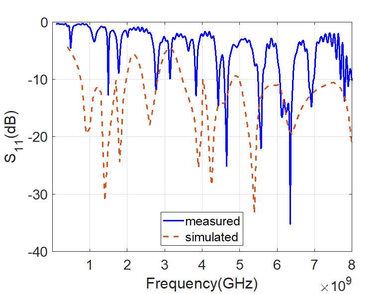 Figure 12: Comparison of S11 obtained in measurements and simulations results for prototype in Figure 11.
 Figure 13: Antenna prototype with slots with the feed at the 3rd fingertip.
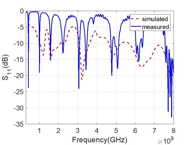 Figure 14: Comparison of S11 obtained in measurements and simulations results for prototype Figure 13.
Third prototype, with slots and feed at the first fingertip (Figure 9) :
Adding slots along all fingers has created multi band operation for feed at all fingertips due to elongating the current path. Here the feed is at the first fingertip as shown simulated results show more like ultra wide band operation below 4 GHz. Common nature of multi-band operation is seen in both results with peaks almost coinciding or falling within matching region i.e for S11 belwo -10 dB. in Figure 9. Comaprision between measured and simulated results is shown in Figure 10. Measured results resonance is obtained at 2.15, 4.5, 5, 5.5, 6.05, 6.8 and 7.7 [GHz], while simulated results show more ultra wide band operation above 4 GHz in addition to several multi-band rsonances belwo 4 GHz. Multiple bands are seen in both results,
with peaks almost coinciding or falling within matching region i.e for S11 below -10 dB.
Fourth prototype, with slots and feed at the second fingertip (Figure 11) :
Adding slots with the coaxial feed position at the second fingertip is shown in Figure 11. The S11 measurements show good matching with simulation results ( Figure 12) at the following resonant frequencies : 1.4, 1.83, 2.72, 3.9, 4.2, 4.78, 5.38, 6.32,6.97,8 [GHz] being the simulated obtained values with maximum difference of 0.25 [GHz]. Resonance at 1 [GHz] did not appear strong enough in measurements, hence it is not considered.
Fourth prototype, with slots and feed at the third fingertip (Figure 13) :
Adding slots with the coaxial feed position at the third fingertip is shown in Figure 13. The S11 measurements show good matching with simulation results in Figure 14, at the following resonant frequencies : 0.15, 1, 1.65, 2.25, 3, 3.4, 4.8, 5.08, 6.2, and [7.6-8] [GHz]. Resonance in measurements at 0.4 [GHz] could not be obtained in simulated results and hence it is not considered.
5. Dc biasing of mounted varactors
A simple experimental approach of adding varactors across slots was done as an arbitrary trial to check resonances and reconfigurabilty with DC biasing [26]. Simulations were not done to approve results as this experiment falls in further studies to explore the full frequency reconfigurability upon adding varactors. Moreover, experimental tools did not allow DC biasing to the full range of voltage, which is up to 60 V due to summing up the voltage across varactors, which take up to6 V each. As shown in Figure 15, varactors were added at the slots carved through second and third fingers. In order to DC bias the 13 varactors. Inductors were added across slots in 1st and 4th fingers as shown in Figure 15. Hence DC current was drawn through the inductors, which act as AC block at the same time [26]. S11 resonance at low frequencies is remarkable considering the size of the antenna. Frequency reconfigurability over [2.15-2.25] and [0.2-0.8] GHz is obtained upon DC biasing the antennas between [0-10] V as shown in Figure 16. Future studies are to be made by further increasing the DC voltage biasing range. Applications to such frequencies fall in DVB, TV broadcast, LTE, and many other telecommunications standards, which allow -6 dB S11 at maximum return loss [14]. Additional new frequency resonances are obtained at1, 1.6 and 2.15 [GHz] due to adding varactors as shown in Figure 16. The multi-band feature of the antenna at wide range of frequencies enables additional applications such as IOT [6] and energy harvesting [4,27].
 Figure 15: Antenna prototype with slots with the feed between 1st and 2nd fingertip and using varactors along 2nd and 3rd fingers slots.
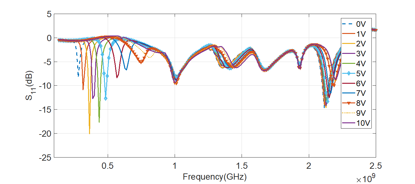 Figure 16: Comparison of S11 obtained in measurements and simulations of prototype in Figure 15 with frequency tunability upon varying the DC bias voltage.
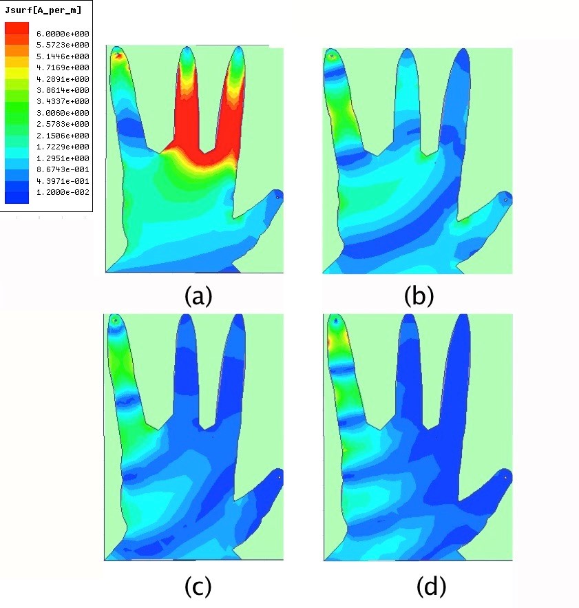
Figure 17: Simulated results for the current distribution for the 4 resonant cases corresponding to 1.66 GHz (Figure a), 3.95 GHz (Figure b), 5.2 GHz (Figure c), and 7.2 GHz (Figure d).
6. Surface current density
Current flow at the antenna surface changes with frequency, consistently with the electric length required for frequency resonance [28]. Surface current density distribution is plotted from simulations for four frequencies as a demonstration. The first antenna prototype in Figure 6 is chosen as an example. Here the feed is at the 4th fingertip. Figure 17 shows the four current graphs corresponding to 1.66, 3.95, 5.2 and 7.2 [GHz] with same color scale with maximum at 6 [A.m-1] and minimum at 0.012 [A.m-1]. However, at 1.66 [GHz] the current density achieves highest value of 60 [A.m-1]. Normally, lowest frequency corresponds to largest electric length and current density values. The current is first strong especially over the mid part of the hand 1.66 [GHz] in graph(a) of Figure 17; then the current surface area diminishes as frequency increases as shown in graphs (b,c,d) of Figure 17. Of course, longest current path from input feed to furthest points in the patch assures the lowest frequency resonance. And obviously, the current is drawn to smallest area around the fourth fingertip where the feed is placed, at the highest frequency of 7.2 [GHz] as shown in graph (d) in Figure 17.
7. Radiation pattern
The current flow distribution in Figure 17 radiates the different patterns shown in Figure 18, [28]. The radiation pattern at the 2.43 GHz frequency is shown in Figure 18 (a). The common observed feature at low resonant frequencies is the symmetric current distribution with respect to the right diagonal resulting in a common radiation pattern at 1.66 and 2.43 [GHz]. Here, the axes are same as in Figure 5. Figure (b) has many peaks due to non-symmetric current density at 6.15 [GHz]. Figures 18 (a, b) show the main trend of radiation pattern at low (1.66 and 3.95 [GHz]) and high frequencies (above 5.2 [GHz]) respectively, as a consequence of change of current density symmetric distribution on the surface. A more description plot of the radiation pattern at 2.43 [GHz] is shown in Figure 19.
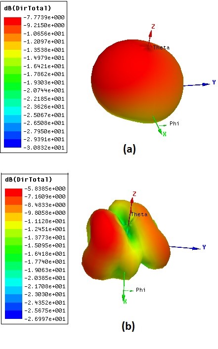 Figure 18: Radiation pattern at 2.43 and 6.15 [GHz] in (a) and (b) respectively.
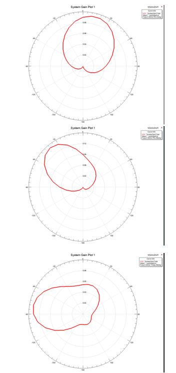 Figure 19: 2D radiation Pattern in XOZ, YOZ, and XOY planes from top to bottom respectively.
8. Conclusion
The ‘Hand of God’ motif has been successfully translated in antenna design modeling and served in achieving a multi-band operation. Slots are incorporated in the antenna showing an enhanced multi-band operation. In fact, 10 resonant frequencies were obtained over the interval [0.15-8] GHz for one prototype having slots and with the feed at third fingertip. Interesting increase in electrical length of the antenna results when varactors are added across slots. Consequently, resonance at low frequencies of 100 MHz is obtained. Moreover, frequency reconfigurability is observed at frequencies below 1 [GHz]. Finally, the shape, size, and wide range of antenna operation frequencies render it as multi-functional and suitable for different modern applications.
- Balanis, C. A. ‘Antenna Theory’. (Wiley and Sons, INC., 1997).
- Ghosal, A., Majumdar, A., Das S. K., & Das A. (2018). ‘A multiband microstrip antenna for communication system’. 2018 Emerging Trends in Electronic Devices and Computational Techniques (EDCT), Kolkata, 1-4.
- Xu, K. D., Li, D., Liu, Y., & Liu, Q. H. (2018). ‘Printed Quasi-Yagi Antennas Using Antennas Using Double Dipoles and Stub-Loaded Technique for Multi- Band and Broadband Applications’. IEEE Access, 6, 31695-31702.
- Chen, Y., Liu, Q., Tang, X., Mo, Z., Li, C., & Li, F. (2018). ‘Compact triple band circularly polarized directional antenna for UHF/ISM RFID mobile readers with GNSS band’. 2018 International Workshop on Antenna Technology (iWAT), Nanjing, 1-3.
- Li, Y., Sim, C., Luo Y., & Yang G. (2018). ‘Multiband 10-Antenna Array for Sub-6 GHz MIMO Applications in 5-G Smartphones’. IEEE Access, 6, 28041-28053.
- Mansour, A. M. et al. (2016). ‘Compact reconfigurable multi-size pixel antenna for cognitive radio networks and IoT environments’. 2016 Loughborough Antennas & Propagation Conference (LAPC), Loughborough, 1-5.
- Hui, D. (2017). ‘A new type of multi-band mobile phone antenna for 3G&4G network’, 659-63.
- Wang, J. J. H., and Adley, J. C. (2017). ’30-2000 MHz multi-band body wearable antenna (MBWA)’, 1771-2.
- Ozbakis, B., Okuyucu, S., Seemen, M. & Yegin, K., (2017). ‘Multi-band frequency tunable LTE antenna for mobile phone applications’, 939-43.
- Shahzad, M. U., Ahmed, W., Bukhari, S. M. R., Hassan F., & Shahid, H. (2017). ‘Multiple band reconfigurable dual H-shaped patch antenna’. 2017 International Symposium on Recent Advances in Electrical Engineering (RAEE), Islamabad, 1-4.
- patents.google.com/patent/US8629811B2/en, 2014.
- Labidi, M., Salhi, R., and Choubani, F., (2017). ‘A design of metamaterial multi-band bowtie antenna based on omega-shaped resonator’, Applied Physics A, 123(5), 1-6.
- Zhang, Q., & Gao, Y. (2017). ‘Compact low-profile uwb antenna with characteristic mode analysis for uhf tv white space devices’. IET Microwaves, Antennas Propagation, 11(11).
- Al-Husseini, M., Kabalan, K. Y., El-Hajj, A., Christodoulou, C. G., ‘Reconfigurable microstrip antennas for cognitive radio’, in Kishk, A., ‘Advancement in Microstrip Antennas with Recent Applications’. (InTech, 2013).
- en.wikipedia.org/wiki/Hand_of_God(art), 2018.
- Mahesh, A., Shushrutha, K. S. & Shukla, R. K. (2017). ‘Design of multi-band antennas for wireless communication applications’. 2017 IEEE Applied Electromagnetics Conference (AEMC), Aurangabad. 1-2.
- https://i.pinimg.com/564x/91/84/14/91841435effbcaddf955790f09ed4402.jpg
- K. Sharma, B. V. R. Reddy and A. Mittal, “Slot Loaded Microstrip Patch Antenna for WLAN and WiMax Applications,” 2015 IEEE International Conference on Computational Intelligence & Communication Technology, Ghaziabad, 2015, pp. 597-599.
- S. E. Muthumani, Vallikannu R and H. R. Patnam, “Compact slot loaded Koch fractal microstrip patch antenna,” 2013 IEEE Applied Electromagnetics Conference (AEMC), Bhubaneswar, 2013, pp. 1-2.
- S. Verma, J. A. Ansari and M. K. Verma, “A novel compact multi-band microstrip antenna with multiple narrow slits,” Microwave and Optical Technology Letters, vol. 55, (6), pp. 1196-1198, 2013.
- S. Ghosal and S. R. B. Chaudhuri, “Analysis of a rectangular slot on a microstrip patch antenna with an equivalent circuit model,” 2013 IEEE Applied Electromagnetics Conference (AEMC), Bhubaneswar, 2013, pp. 1-2.
- Q. Bai et al, “An Independently Tunable Tri-Band Antenna Design for Concurrent Multiband Single Chain Radio Receivers,” IEEE Transactions on Antennas and Propagation, vol. 65, (12), pp. 6290-6297, 2017.
- C. Deng et al, “A Novel Low-Profile Hepta-Band Handset Antenna Using Modes Controlling Method,” IEEE Transactions on Antennas and Propagation, vol. 63, (2), pp. 799-804, 2015.
- K. K. Kishor and S. V. Hum, “Multiport Multiband Chassis-Mode Antenna Design Using Characteristic Modes,” IEEE Antennas and Wireless Propagation Letters, vol. 16, pp. 609-612, 2017.
- Y. Li et al, “Compact Heptaband Reconfigurable Loop Antenna for Mobile Handset,” IEEE Antennas and Wireless Propagation Letters, vol. 10, pp. 1162-1165, 2011.
- Madi, M., Al-Husseini, M. & Kabalan, K. Y. (2018). ‘Frequency Tunable Cedar-Shaped Antenna for WIFI and WIMAX’. Progress In Electromagnetics Research Letters. 72, 135–143.
- Alsharoa, A., Neihart, N. M., Kim, S. W., & Kamal A. E., (2018). ‘Multi- Band RF Energy and Spectrum Harvesting in Cognitive Radio’. Networks. 2018 IEEE International Conference Communications (ICC), Kansas City, MO. 1-6.
- Madi, M. & Kabalan, K. Y. (2018). ‘Multi-Band Hand of God Antenna for Wireless Communications’. ICT conf., St Malo, France, July, IEEE proc