Optimization of the Stabilizer Bar by Using Total Scores Method

Adv. Sci. Technol. Eng. Syst. J. 5(1), 431–435 (2020);
 DOI: 10.25046/aj050155
The stabilizer bar restricts the roll angle of the vehicle when the vehicle steers based on the load balance on both sides of the wheel. Usually, the bar is in the form of the symmetrical U-shaped with the diameter is circular or annular. In order to be able to calculate the diameter of the stabilizer bar, it is necessary to determine the value of force F acting on the arm of the stabilizer bar. Previous studies often estimate the force value F is a defined constant, thus causing inaccuracy in the calculation process. This study focuses on accurately determining the maximum force value F to optimize the size of the bar. The size of the bar is optimized based on the values of the mass and the displacement. The results of the study indicate that the bar with the annular section will be more optimal in terms of mass and displacement than the circular section. In most cases, if the thickness of the bar decreases, the mass and the displacement of the bar also tend to decrease.
1. Introduction
When the vehicle steers, under the influence of centrifugal force will cause the vehicle body to be tilted and change the load on both sides of the wheel [1, 2]. The stabilizer bar is used to restrict the roll angle of the vehicle when steering, redistribute the load on both sides of the wheel, thereby supporting the vehicle to move more stably and safely [3–5].
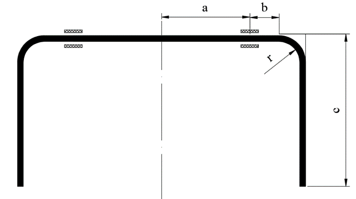
The stabilizer bar in Figure 1 has a structure consisting of two parts: the back and the arm. Normally, the stabilizer bar is in the form of symmetrical U-shaped with constant diameter along the length, some bars can be hollowed out to reduce mass [6–8]. The size and geometric parameters of the bar depend on the position of the bar layout on the vehicle.
When the load on both sides of the wheel changes, the arm will move in opposite directions, causing opposite torque on the back of the bar. These moment values are similar, so they cancel each other out and make the vehicle more stable.
Previous studies often focused on calculating the stresses and displacements of bars. In order to be simplified during the calculation process, the force value F acting on the arm of the stabilizer bar is generally estimated [9–13]. However, this method will cause major disadvantages as follows:
If the value of the force F is too small, the diameter of the bar will be small. Therefore, special moving conditions may affect the durability and reliability of the bar. Besides, when the vehicle is tilted too large, it will cause the arm’s displacement to exceed the limited space.
If the value of force F is too large, the diameter of the bar will be too large. Therefore, it will affect the layout of the bar on the vehicle. Besides, if the size of the bar is too large, the unsprung mass will increase, causing a loss of comfort for the passenger.
This study focuses on optimizing the size of the stabilizer bar based on the exact determination of the force value acting on the arm. Additionally, the study also establishes the dependence between the roll acceleration and the vehicle’s mass and velocity.
2. Determine the diameter of the stabilizer bar
2.1. Requirements for the stabilizer bar
With the function of limiting the roll angle of the vehicle body when steering, the stabilizer bar on the vehicle needs to meet some requirements when designing such as:
- Generate anti-roll moments large enough to limit the roll angle.
- Ensuring torsional and bending conditions during operation (especially for large size vehicles).
- The geometry and displacement must be reasonable.
- The mass is small and limited to affect the comfort of the vehicle.
2.2. Determine the force value acting on the stabilizer bar
The force value acting on the arm of the stabilizer bar can be determined as follows: [14]
\(${\Delta}F=\left|F_{i} – \frac{mg}{2} \right|$\) (1)
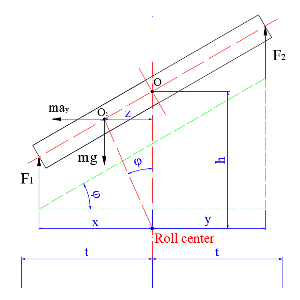
When the vehicle body is tilted, the trajectory of the center is an arc with a radius is the distance from the center of gravity to the roll center [15]. The maximum force value acting on the arm of the stabilizer bar will be:
\($F_{max} = \frac{mh(gtan\Phi + a_{ymax})}{2t}$\) (2)
where
Fi: The force of the suspension system.
\($\Phi$\)max: The limited roll angle of the vehicle body.
aymax: The limited lateral acceleration of the vehicle (respectively to jmax).
Assume that: u is the roll acceleration:
\($u = gtan\Phi + a_{ymax}$\) (3)
The formula (2) can be rewritten as:
\($F_{max} = \frac{mhu}{2t}$\) (4)
From (4) can see that:
- The load acting on the stabilizer bar is proportional to the mass and dimension of the vehicle. However, the values of mass and dimension are unchanged when the vehicle moves on the road.
- Load acting on the stabilizer bar depends on roll angle and lateral acceleration of the vehicle. These two values vary according to the velocity, steering angle, road surface conditions and other effects of external forces.
Therefore, in order to determine the maximum load value acting on the arm part of the stabilizer bar, the limit values \($\Phi$\)max and aymax need to be determined. However, in different conditions, the limit of roll angle and lateral acceleration will be different, it is difficult to accurately determine these values. Normally, there will be 2 cases of interest:
Case 1: Vehicle steers unstable (steering angle is large, steering acceleration is high) at a high speed, the vehicle will rollover very fast while \($\Phi$\)max and aymax are still not big enough.
Case 2: Vehicle steers stable (steering angle is small) at high speed, the value of \($\Phi$\)max and aymax will be larger.
Therefore, the maximum force value acting on the arm of the stabilizer bar will be determined according to the second case.
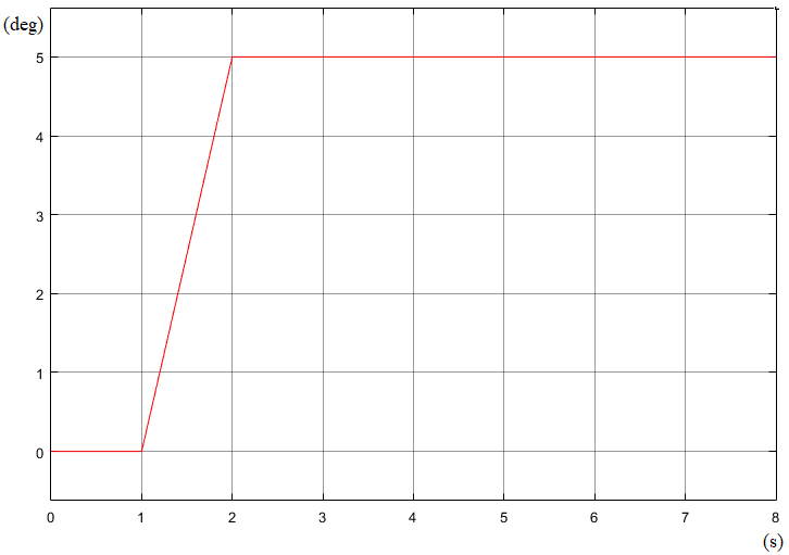
Using the established dynamic vehicle model [16], reference vehicle parameters such as Table 1 and steering angle as shown in Figure 3. The graph shows the dependence of the roll acceleration on the mass and velocity of the vehicle is given as shown in Figure 4.
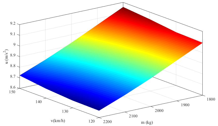
From the graph in Figure 4, it can be seen that:
- When the sprung mass increases, the value of the roll acceleration tends to decrease.
- When the speed increases, the value of the roll acceleration increase.
Therefore, the force value F acting on the arm of the stabilizer bar is taken in case the vehicle moves at high velocity.
2.3. Calculation of the stabilizer bar
The stabilizer bar must ensure torsional and bending conditions during work. The diameter of the stabilizer bar is determined by following the below formula [17]:
\($D \ge \sqrt[3]{\frac{16F\sqrt{4(b + r)^2 + 3c^2}}{\pi[\sigma]}}$\) (5)
Where: D is the outer diameter and d is the internal diameter of the stabilizer bar.
After determining the diameter of the stabilizer bar. The mass of the stabilizer bar can be calculated based on the formula (6):
\($m_{sb} = \frac{1}{2}\rho\pi \left(D^2 – d^2\right)\left(a + b + c + \frac{\pi{r}}{2}\right)$\) (6)
According to [18], the displacement of the stabilizer bar can be determined as follows:
\($\delta = \frac{F(b + r)^3}{3EJ_x} + ctan\beta$\) (7)
with β is the torsional angle of the stabilizer bar:
\($\beta = \int_0^{a+b}\frac{Fc}{GJ_p} dz$\) (8)
2.4. Optimization of the stabilizer bar
Use reference parameters as shown in Table 1.
The simulation performed at the velocity value v = 150 km/h, the value of the roll acceleration is determined from the Figure 4. The diameter, mass, and displacement of the stabilizer bar are given as shown in Table 2.
From Table 2, it was found that:
- For solid bars, the outside diameter is small but the mass and displacement of the bar are very large.
- For hollow bars, the mass and displacement will vary depending on the thickness of the bar.
- If the stabilizer bar is optimized in terms of total scores, the optimal value can be used as d1 = 24 (mm); D1 = 30 (mm) or d2 = 25 (mm); D2 = 31 (mm).
Table 1: Reference parameters.
| Description | Symbol | Value | Unit |
| Sprung mass | m | 2000 | kg |
| Distance from center of gravity to front axle | l1 | 1300 | mm |
| Distance from center of gravity to rear axle | l2 | 1700 | mm |
| Distance from bearing to center | a | 300 | mm |
| Distance from bearing to bending angle | b | 130 | mm |
| Length of the arm | c | 250 | mm |
| The radius of curvature | r | 70 | mm |
| Limited stress | σ | 1200 | MPa |
| Density | r | 7800 | kg/m3 |
Table 2: The size of the stabilizer bar.
| Inner diameter
(mm) |
Outer diameter
(mm) |
Mass
(kg) |
Score 1 | Displacement
(mm) |
Score 2 | Total score |
| 0 | 23 | 5.12 | 1 | 61.64 | 1 | 2 |
| 10 | 24 | 4.61 | 2 | 53.39 | 4 | 6 |
| 11 | 24 | 4.40 | 4 | 54.19 | 3 | 7 |
| 12 | 24 | 4.18 | 5 | 55.28 | 2 | 7 |
| 13 | 25 | 4.41 | 3 | 47.33 | 7 | 10 |
| 14 | 25 | 4.15 | 6 | 48.68 | 6 | 12 |
| 15 | 25 | 3.87 | 9 | 50.46 | 5 | 14 |
| 16 | 26 | 4.07 | 7 | 43.72 | 9 | 16 |
| 17 | 26 | 3.75 | 10 | 45.86 | 8 | 18 |
| 18 | 27 | 3.92 | 8 | 40.08 | 12 | 20 |
| 19 | 27 | 3.56 | 12 | 42.65 | 10 | 22 |
| 20 | 28 | 3.72 | 11 | 37.56 | 14 | 25 |
| 21 | 28 | 3.32 | 14 | 40.69 | 11 | 25 |
| 22 | 29 | 3.46 | 13 | 36.09 | 15 | 28 |
| 23 | 29 | 3.02 | 17 | 39.98 | 13 | 30 |
| 24 | 30 | 3.14 | 16 | 35.69 | 16 | 32 |
| 25 | 31 | 3.25 | 15 | 31.99 | 17 | 32 |
3. Conclusion
The stabilizer bar restricts the roll angle when the vehicle steers, and evenly distributes the load on both sides of the wheel, assisting a smooth wheel on the road.
The size of the stabilizer bar greatly affects the mass and displacement of the bar. If the bar is thinner and smaller, the mass and displacement of the stabilizer bar to decrease. Therefore, the comfort of the vehicle will be increased.
The stabilizer bar optimization process to find the most suitable dimension value. Therefore, it can reduce the mass and save materials in the production process.
The results of the study indicated that: With the vehicle specification used, the optimum size of the stabilizer bar was chosen as d1 = 24 (mm); D1 = 30 (mm) or d2 = 25 (mm); D2 = 31 (mm). In the case of the mass of the stabilizer bar is optimized, the size d1; D1 should be used. However, if the displacement of the stabilizer bar is optimized, the size d2; D2 should be used.
This research has only provided the optimal theoretical calculation method. Experimentation is needed to get the best effect.
- N. K. Trai, N. T. Hoan, H. H. Hai, P. H. Huong, N. V. Chuong, T. M. Hoang, Structure Vehicle, Bach Khoa Hanoi Publishing, 2010.
- R. Rajamani, Vehicle Dynamics and Control, Springer Publishing, 2012. DOI: 10.1007/978-1-4614-1433-9
- A. N. Khartode, M. U. Gaikwad, “Design, and Analysis of Anti-roll Bars for Automotive Application”, International Journal on Recent and Innovation Trends in Computing and Communication, 4(6), 340–345, 2016.
- R. Stone, J. K. Ball, Automotive Engineering Fundamentals, SAE International Publishing, 2004.
- H. Bankar, R. Kharade, P. Baskar, “Finite Element Analysis of Anti-roll Bar to Optimize the Stiffness of the Anti-roll Bar and the Body Roll”, International Journal of Model Engineering Research, 3(10), 11–23, 2014.
- S. Ramakrishna, B. R. H. Reddy, B. Akhil, B. P. Kumar, “A Review on Anti-roll Bar Used in Locomotives and Vehicles”, International Journal of Current Engineering and Technology, 7(3), 838–841, 2017.
- A. P. P. Mariappa, Design and Optimization of Anti-roll Bar, Master Thesis, Kaunas University of Technology, 2018.
- S. B. Tuljapure, L. S. Kanna, “Analysis on Stability Bar”, Advanced Materials Manufacturing & Characterization, 3(1), 349–354, 2013.b
- P. Bharane, K. Tanpure, A. Patil, G. Kerkal, “Design, Analysis, and Optimization of Anti-roll Bar”, International Journal of Engineering Research and Applications, 4(9), 137–140, 2014.
- P. G. Jamode, J. S. Gawande, T. S. Hingve, “Structural Analysis and Validation of Anti-roll Bar”, International Journal of Interdisciplinary Innovative Research and Development, 1(4), 72–74, 2017.
- K. K. Sharma, A. Rashid, S. Mandale, “Analysis of Anti-roll Bar to Optimize the Stiffness”, International Journal of Modern Trends in Engineering and Research, 2(7), 1874–1879, 2015.
- A. M. Wittek, D. Gaska, B. Lazarz, T. Matyja, “Automotive Stabilizer Bar– Stabilizer Bar Strength Calculations Using FEM, Ovalization of Radial Areas of Tubular Stabilizer Bar”, Mechanika Journal, 20(6), 535–542, 2014. DOI: 10.5755/j01.mech.20.6.7706
- N. T. Anh, “Study on the Load Distribution of the Vehicle When Steering at Different Velocities”, International Journal of Innovative Science and Research Technology, 4(5), 433–435, 2019.
- N. T. Anh, H. T. Binh, “Study on the Influence of Vehicle’s Dimension to Rollover”, International Journal of Science and Engineering Investigations, 8(5), 62–64, 2019.
- N. T. Anh, H. T. Binh, “Research on Determining the Limited Roll Angle of Vehicle”, Advances in Engineering Research and Application, Lecture Notes in Network and Systems, vol. 104, 613–619, 2020. DOI: 10.1007/978-3-030-37497-6_70
- T. T. Hung, Strength of Materials, Science and Technology Publishing, 2006.
- N. T. Anh, T. T. Tran, H. T. Binh, P. H. Nam, L. T. Dung, “The Study on the Method of Calculating and Designing the Stabilizer Bar on the Vehicle Using Solidworks Software”, Vietnam Mechanical Engineering Journal, 7(12), 92–99, 2018.