Power Converters and EMS for Fuel Cells CCHP Applications: A Structural and Extended Review

Adv. Sci. Technol. Eng. Syst. J. 6(3), 54–83 (2021);
 DOI: 10.25046/aj060308
Fuel Cells (FCs) and Combined Cooling, Heating and Power (CCHP) systems are becoming very popular due to their environmental friendliness and immense applications. This extended review paper commenced by introducing the rampant South Africa’s electricity crisis as the basis for the study, followed by some structural analyses of up to forty-four miscellaneous power electronics converters case studies applicable to fuel cells including at least sixteen FCs energy management systems (EMS) applicable case studies. The review rationale is to determine innovative best practices that can be applied to devise an efficient power converter and EMS for an energy efficient FC CCHP system. From these analyses, it is realized that each power converter and EMS scheme has its merits and demerits depending on the targeted applications and most importantly the research project objectives – that is, whether the goals are to reduce costs, enhance efficiency, reduce size, boost performance, simplicity, durability, reliability, safety etc. Therefore, the conclusion drawn is, there is no “one size fits all” approach, as all the various reviewed case studies reported relatively good results based on their chosen schemes for their targeted applications. Notwithstanding, this review highlights are, i) the interleaved boost converter and variants as well as ii) the maximum power point tracking (MPPT) technique; are the most widely used schemes, as they are reasonably effective and simple to implement. The contributions brought forward are i) an apt single reference study that presents a quick topological insight and synopsis of assorted FCs power converters as well as EMS and ii) our proffered FC CCHP system undergoing research to offer an innovative energy efficient solution for basic household energy needs such as electricity, heating, cooling and lighting.
1. Introduction
Compounded with re-occurring electrical energy and power problems in South Africa and at large Africa; this extended article to [1], extensively investigates with emphasis on fuel cells (FCs), some assorted research on power converters and energy management systems / storage (EMSs) techniques. Currently, there’s up to 2 hours of daily electricity rolling blackouts in South Africa (RSA), due to RSA national energy utility company (ESKOM) inability to generate enough energy to meet its local electricity demands. This is due to the legacy apartheid energy system being over-stretched with more underprivileged areas / users now having access to electricity, old energy infrastructures being upgraded, poorly designed and in-efficient new energy infrastructures, poor technical maintenance, inadequate technical abilities, corruption as well as illicit business and political reasons.
Thus, various optional renewable energy sources, especially solar and wind powers are being commissioned to augment and or stabilize RSA national grid supply and also for personal use. Alternative energy sources such as i) FCs − which produce power and heat as well as water when fueled with H2 and O2 and ii) thermo-electricity − which simply generates a) electricity based-on Seebeck effect and b) heat / cold based-on Peltier effect, are of interests. In this regard, our research focuses on FCs and thermo-electricity; however, these clean energy sources need supporting technologies and techniques to operate well. In light of this, we review applicable best practices that can be developed to execute an energy efficient fuel cell alternative power / energy system for domestic and commercial combined cooling, heating and power (CCHP) applications − since electricity, heat / cold and light are the most commonly used forms of energy in most homes in RSA. FCs CCHP systems are versatile, clean and becoming very trendy; thus, discussed next are miscellaneous power converters and EMS research applicable to FCs and by extension FC CCHP systems.
A fuel cell stack closed-circuit voltage is a function of the FC activation, concentration and Ohmic losses governed by the Nernst equation. This FC loaded condition draws more current resulting to a voltage dip/drop as a result of delay of Hydrogen / Oxygen flow and this phenomenon is called the fuel cell fuel starvation. This voltage drop and the load current together with other FC parameters, establish the degree and duration of the problem. This issue is tackled diversely as analyzed briefly in [1].
In [1]-[36], DC-DC power converters are paramount to either boost and or reduce DC power sources (e.g FCs) and then sustain a consistent power thereafter. FCs typically produce low DC voltage but high current, which combined with the possibility to fluctuate when connected to a load, demands power regulations to the DC bus and ultimately to the different DC and or AC loads.
In DC-DC power converters, with the exception of linear regulators, the fundamental three switching kinds are the step-down, step-up and step-up / step-down − from which various and or improved versions are derived to give isolated derivatives with one or multiple switches including the soft-switching versions.
The voltage output from step-down DC-DC power converters, is always lesser than its voltage input. Contrarily, the voltage output from a step-up DC-DC converter is always more than its voltage input. The step-down / step-up power converter based-on its duty cycle value; can respectively either lower (duty cycle < 0.5) or increment (duty cycle > 0.5) the converter voltage output.
As per [37]-[70], EMSs are essential to manage the power converters to ensure maximum power is transferred to the load, the bus is stable and the energy / power supply system is efficient.
2. Power Converters
Power converters are required to buck, boost and provide regulated voltage to the DC bus. In what follows and summarized in Table 1, are miscellaneous case studies that structurally analyzed in brief details, some power converters for use with FCs.
2.1. DC-DC Power Converters Architectures for Fuel Cells Applications
As presented in [23], power sources based on fuel cells are now trendy devices. They offer reliability, flexibility as well as efficiency through multi-stack topologies. To access the market requires simplifying further the FCs design and its supporting components, which among others include the power converters which ensure the output voltage is regulated. Their research thus focused on DC-DC power converters by giving an inclusive outline on the interfaces of power converters for use in aircraft, railways, automotive and small static areas such as households.
The significance of selecting the correct power converters topology and the related technology is crucial, as its facets allow thermal compatibility with various methods for integrating the DC-DC power converters to the fuel cells. These topological and technological features that have been examined and displayed in Figures 1a -1f with highlights in Figures 1e -1f, are some popular power converters topologies. In their study, they indicated how connecting a fuel cell stack / DC-DC power converters in parallel and in series increase the current and voltage outputs respectively.
 Figure 1: DC-DC Power Converters Architectures for Fuel Cells Applications (adapted from [23])
Explained in their research and portrayed in Figures 1c and 1d, are non-isolated multi-phase boost converters, which are mainly appropriate for applications that require low DC bus voltage. The interleaved topologies shown, meet the prerequisite for curbing low FC ripple currents. The depicted standard interleaved boost converter (IBC) shown in Figure 1c and the floating interleaved converter (FIC) in Figure 1d, show similar merits. Z-sources inverters (ZSI) were also articulated, in which their features and merits make them suitable choices for 3-phase electric drives − for instance automotive / railway applications. Furthermore, the study indicated that the isolated converters based-on high frequency planar transformer (which according to [23], only one quantity was left in the market in 2014), is beneficial in high DC link voltage applications such as railway. Contrarily, the isolated converters give a low efficiency for medium power applications. However, the soft-switching function enables the enhancement of the converter efficiency but at the cost of using supplementary components in the converter configurations. These improvements are shown in Figures 1e and 1f − whereby the half-bridge isolated converter (HIC) and the current-fed full-bridge resonant isolated converter (RIC), respectively illustrate the zero-voltage switching (ZVS) and zero current switching (ZCS) operations, in which both increase the efficiency by reducing the devices switching losses. The technological review on the other hand focused on the new wideband-gap semiconductor materials and the utilization of Silicon Carbide (SiC) and Gallium Nitride (GaN) devices with low on-resistance, high power densities and high speed switching with less losses, which could transcend to major improvements in the power converters performance. Nowadays, GaN devices are suited for low/mid power applications, whereas SiC technology is more desirable for designing high power FCs DC-DC converters.
2.2. State-of-the-Art Fuel Cells DC-DC Converters
According to [13], fuel cells are current intensive sources that have become popular. The study presented various suitable topologies of DC-DC power converters for FCs output voltage conditioning. The goal of the main DC-DC power converter between the FC and DC bus was emphasized, which demands the power converter be designed/operated using high efficiency, high voltage ratio and high density with low-cost. As a result, their paper highlighted some tips in this regard as well as the positives and negatives. Some of the schemes are shown in Figures 2a – 2c.
 Figure 2: Fuel Cells DC-DC Power Converters (adapted from [13])
2.3. A Soft Switched Push-pull Current-fed Converter for FC Applications
Examined in [14], a zero-voltage switching (ZVS) current-fed push pull DC–DC converter is suggested for fuel cells power generation system as pictured in Figure 3. In the study, the auxiliary circuit in this converter supplies ZVS condition for all converter switches which reduces switching losses and further absorbs at turnoff instances, the voltage surge across the switches.
This merit, enhances the converter efficiency and reduces the size and converter weight – which henceforth enables the implementation of a very simple control circuit based on pulse width modulation (PWM). This setup was then used to analyse and validate the operation of the converter using a lab prototype. The projected DC-DC power converter experimental results, the various operating modes as well as their corresponding timing waveforms, are presented in detailed in their published paper.
 Figure 3: The Proposed Soft Switched Push-pull Current-fed Converter (adapted from [14])
2.4. Topology of FC Hybrid Power Source for Efficient Operation and High Reliability
Proposed in [15], is a fuel cell hybrid power source (HPS) topology with the attribute to curb the ripple current of the FC inverter system. The ripple current usually occurs at the DC port of the FC HPS when operating the inverter system − which is connected to the grid or which supplies AC motors in vehicular applications. As a result, if the alleviation measures are not implemented, this ripple current is propagated back to the FC stack. The suggested FC HPS has other good performance features; such as the maximum power point tracking (MPPT), high steadfastness in operation during transient power pulses and finally improved energy efficiency in peak power applications.
 Figure 4: The Proposed Hybrid Power Source Topology (adapted from [15])
To mitigate the ripple, this approach made use of an inverter system powered directly from the FC stack with a controlled buck current source that was used as the low power source. The low frequency (LF) ripple reduction is rooted in active control, whereby the anti-ripple current is injected in HPS output node and this has the LF power spectrum similar to the inverter ripple. In light of this, the fuel cell ripple current was curbed by the designed active control. Indicators defined to evaluate the mitigation ratio of the LF harmonics were used to assess the ripple current alleviation performances. The relatively good performances shown were attained with the use of a hysteresis current control, but better if a devoted nonlinear controller is used, which can be designed in two ways as follows i) simulation trials that assist to draw the attributes of ripple mitigation ratio verse fuel cell ripple current and ii) fuzzy logic controller (FLC). The ripple factor was ~ 1% in both cases. Figure 4 depicts the study.
2.5. Power Flow Control Methods for Ultra-capacitor Bidirectional Converter in DC Micro-grid
Postulated in [16], distributed generation (DG) in the form of DC micro-grids depicted in Figure 5a, has recently attracted increasing research interests. A bidirectional DC-DC converter (BDC) shown in Figure 5b, is required to incorporate renewable energy resources and energy storage devices such as an ultra-capacitor (UC) to the DC bus of a DC micro-grid to sustain the charging and discharging states of the ultra-capacitor. For the quick dynamic response of the ultra-capacitor, a bidirectional voltage-fed setup is suitable, though for a broad input voltage fluctuation of the ultra-capacitor, this setup manifests a greater circulating power flow and greater conduction losses in the end. Presented in this study are a comprehensive overview on the numerous modulation schemes that are employed to manage the power flow of the bidirectional voltage-fed DC-DC converter for the ultra-capacitor applications. An in-depth analysis of the bidirectional converter investigating the impact of the circulating power flow interval was developed and analytical methods such as the conventional phase-shift control (CPC) modulation were applied to develop alternative modulation schemes to advance the efficiency and performance of the bidirectional power converter.
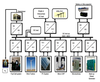 Figure 5 (a): DC Micro-grid Distributed Generation (adapted from [16])
 Figure 5 (b): BDC Power Flow Control Methods for Ultra-capacitor in DC Micro-grid (adapted from [16])
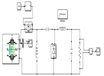
2.6. Fuel Cell and Power Converter Models in MatLab / Simulink
Studied in [19], MatLab and Simulink were employed to model a power converter and PEM FC. Depicted in Figure 6, the first section of the research discussed the methodology for an accurate model for the fuel cell stack, as well as its static and dynamic behaviors − which form a crucial aspect in the design of electrical power generation founded on fuel cells. The technique applied was simulated annealing (SA) optimization algorithm, which justifies its customization to meet the goal of a speedy convergence to institute the correct values for the fuel cell parameters. The correlation between the simulation and the experimental results proved that the suggested model provided an accurate depiction of the static and dynamic behaviors for the PEM FC. The second section of the study engaged on feasible architectures that can be tailored for the DC-DC power converter.
The preferred topology must be suitable to take control and optimize the operation point of the fuel cell; as a result, the soft switching attests to be particularly fitting, especially the series resonant topology converters − because it reduces the switching losses and consequently increasing the efficiency. This converter execution can be explained as follows: the supplied voltage by the stack, which is normally low (29V – 42V), is changed to a constant and high amplitude, in this case, a 400VDC bus is used to generate power to the grid via an inverter. The high frequency (HF) transformer is a boost voltage transformer, which is as well used to offer galvanic isolation between the low and high voltage levels of the circuits. In the primary side of the transformer, the resonant converter with its inductor-capacitor (LC) series resonant circuit, provides the sinusoidal waveforms of voltage and current. The circuit resonant frequency is determined by choosing suitable values for the L and C elements, from which the FC DC voltage is initially inverted to AC in the primary side of the HF transformer and then rectified to DC on the secondary side. The PEM FC is protected from the ripple voltage and current the converter produces by the LC filter in the primary side, which as well stores the DC bus energy. The secondary side LC filter reduces the ripple voltage and current to the load. In conclusion, the simulation results were correlated using actual data acquired from a commercial system. As a result, it was justified that, the hybridization of a suitable power converter using a well-defined controller in conjunction with a well-optimized FC stack model, makes FC good for power generation.
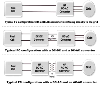 Figure 6: FC Power Converter Models in MatLab / Simulink (adapted from [19])
2.7. High Voltage DC-DC Boost Converter Suitable for Varying DC Voltage Sources
Researched in [11], is a high voltage step-up converter appropriate for varying voltage sources such as photovoltaic (PV) and by extension fuel cells as well as thermo-electric generators (TEGs). Different varying voltage boost sources were assessed to institutes their limits, from which a multi-phase tapped-coupled inductor DC-DC boost converter that can attain high voltage boost ratios from a variable power supply (PV in this case) and without adversely compromising the performance, was then postulated as pictured in Figure 7. The suggested converter achieved minimal voltage and current ripples at both the input and output as well as exhibited reasonable performance at high power levels making it preferred for high power applications. The simulated and practical results correlated to confirm the research.
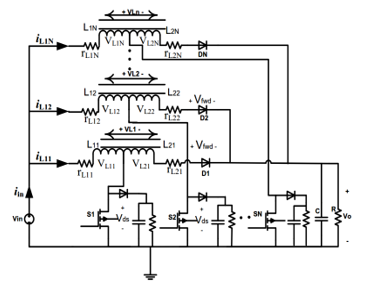 Figure 7: High Voltage DC-DC Boost Converter Suitable for Varying Voltage Sources (adapted from [11])
2.8. High Power Efficient DC-DC Buck Converter Suitable for Varying Voltage Sources
According to [10], in a varying power generation source such as wind (likewise solar-cells and TEGs as well as fuel cells), the power converter efficiency is one of the crucial aspects for the performance of the system. In such systems, the DC-DC step-down converter is usually used for high power systems. Taking into account the cost and efficiency of a converter, their research focus was mainly on the devise of enhanced buck converter topologies with interest on the (inductor, capacitor and diode) LCD converter depicted in Figure 8a – which is to be used for a peak power standalone wind power generation system. A (resistor, capacitor and diode) RCD and an improved RCD buck converter could also remove the voltage spikes; however, it unfortunately further depletes the stored voltage amplitude when the power is switched-off − this is because C1 discharges the voltage stored through R1. Therefore, the need for a LCD version.
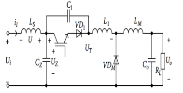 Figure 8 (a): High Power Efficiency DC-DC Buck Converter Suitable for Varying Voltage Sources (adapted from [10])
 Figure 8 (b): DC-DC Buck Converter Climbing Mountain MTTP Algorithm Flowchart for Varying Voltage Sources (adapted from [10])
This issue was addressed by using a better improved LCD buck converter as shown in Figure 8a. This version does not have any resistor but an inductor with negligible energy loss as displayed in the test result. This LCD architecture is also known as zero-voltage switching (ZVS). At resonance, L1 and C1 cancel out, reducing the voltage spike and increasing the switching speed. The practical designed LCD converter is based-on Figure 8a and instead of IGBTs, it uses multi-MOSFETs in parallel to boost the current and the switching speed of the converter. By employing MPPT, the practical utmost efficiency of the designed 2kW DC – DC step-down converter was approximately 96%.
MPPT algorithm ensures the maximum power generated stays constant by monitoring the desired reference output with the generated output and adjusting the duty cycle or PWM signal to the active switch(es) of the power converter. The common MPPT techniques according to [10], includes i) optimum tip speed ratio, ii) power curve control and iii) climbing mountain – the latter was used in the study and its flowchart is illustrated in Figure 8 b.
2.9. High Gain IBC for Fuel Cells Applications
As researched by [9], distributed generation most capable technologies is fuel cell and to design a high efficiency power system using fuel cell, a fitting DC-DC converter is necessary. Among the different DC-DC converters, interleaved converters with switched capacitor are considered a preferred topology for FC systems because of reduced ripple currents in the input and output circuits, quicker transient reaction, small electromagnetic emissions, enhanced efficiency and reliability. This improved conversion efficiency is attained by dividing the output current into ‘n’ parts, to significantly eliminate I2R losses and inductor losses. The research aim was to devise and implement a high gain interleaved boost converter based-on switched capacitors (to improve converter voltage gain) for fuel cell systems. In the interleaved converter proposed, the front-end inductors are magnetically cross-coupled to enhance the electrical performance and reduce the weight and size. By using switched capacitors interfaced with FCs, MatLab and Simulink were used to simulate an interleaved converter, from which a prototype was developed to validate the simulation results. Figure 9 depicts the IBC.
 Figure 9: High Gain IBC for Fuel Cells Applications (adapted from [9])
2.10. High Efficiency Isolated Boost Converters for High-Power Low-Voltage FC Uses
As investigated in [8], fuel cells power systems, as portrayed in Figure 10a, show significant output impedance which reduces the output voltage with increased in the output power; as a result, system peak power is attained at converter smallest input voltage. In light of this, a new low-leakage inductance low-resistance to low-voltage high-power isolated boost converter design technique, was presented as shown in Figure 10b. By optimizing the transformer design and circuit lay-out, very low levels of parasitic circuit inductance were attained. Power MOSFETs fully rated for recurring avalanche, were used to eliminate primary side voltage clamp circuits and switch on-state losses. Furthermore, extensive interleaving of the primary and secondary transformer windings, reduced the transformer proximity effect losses.
Silicon Carbide rectifying diodes are not prone to reverse recovery and therefore allow fast diode turn-off, hence were used to further reduce losses. As illustrated in the study, test results from a 1.5kW full-bridge step-up converter confirmed theoretical analysis and demonstrated a very high efficiency. The maximum efficiency was up to 98% whereas the worst-case efficiency with maximum power and at minimum input voltage was ~ 96.8%.
 Figure 10 (a): Fuel Cell Power Supply System (adapted from [8])
 Figure 10 (b): FC High-Power Low-Voltage High Efficiency Isolated Boost Converters (adapted from [8])
2.11. High Power Buck-Boost DC-DC Converters: Automotive Power-train Applications
Investigated in [12], is a high-power buck-boost DC-DC converter for use in the power-trains of hybrid cars as shown in Figures 11a and 11b. To enable smooth transitions between both energy transfer directions, a special digital control strategy was implemented. Equipped with this feature, the converter can obtain the energy management in the electric power-train.
The digital control provides full protection against over-voltage, over-current and over-temperature. Two efficient prototypes of 24kW and 70kW bidirectional (buck-boost) DC-DC converters were developed and evaluated. The presented measurements show that higher voltages for the power-train and storage battery assure higher efficiency due to lower current losses by the use of IGBTs. Using integrated liquid cooling of up to 85°C with very low losses, a high-power density of up to 5W/cm³ was achieved. Characterization data of the converter and measurements in the target application (a hybrid fuel cell car) with test parameters and values of passive components used, are shown in the study as well as what happens when the converter transits from boost to buck mode. Finally, presented in the full manuscript are voltage and current dynamics as well as the efficiencies and output power in the various operation modes.
 Figure 11 (a): Concept Overview (adapted from [12])
 Figure 11 (b): High Power Buck-Boost DC-DC Converters: Automotive Power-train Applications (adapted from [12])
2.12. PEM FC System with DC-DC Boost Converter: Design, Modelling and Simulation
Indicated in [3], fuel cells as exemplified in Figure 12a, are regarded as one of the most proficient devices for standalone and grid connected distributed generations (DGs), due to their environmental friendliness, modularity and high energy potential capability. The drawbacks in the extensive use of FCs are their i) sluggish dynamic response to abrupt load changes and ii) costly installation. Their research focused on the simulation of dynamic behaviour of a Nexa 1.2kW PEM FC using DC-DC step-up converter, which was correlated with cascaded 2-stack FC model. The performance of the basic DC-DC boost converter as power converter for the Nexa TM 1.2kW PEM FC model was analyzed for changing loads to manage the power flow for improved performance. As the FC pressure or temperature rises, the power density of the FC stack also increases for rising loads; therefore, to analyse this dynamic behaviour for changes against temperature, an advanced parametric model based on circuit simulator PSpice for a class of PEM FC was also developed in addition to the fuel cell models based on thermodynamics and electrochemical equations. The fuel cell performance is governed by its electrical and thermal efficiencies − the electrical efficiency of the fuel cell relies on the fuel cell activation and concentration losses besides the natural Joule heating (Ohmic loss), whereas the thermodynamic efficiency relies on the fuel cell fuel processing, water management and the fuel cell system’s temperature control.
 Figure 12 (a): Fuel Cell Overview (adapted from [3])
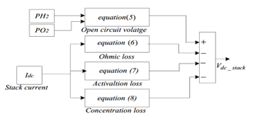 Figure 12 (b): PEM FC System with DC-DC Boost Converter: Design, Modeling and Simulation (adapted from [3])
All these factors were taken into consideration when the design was done using Matlab / Simulink as in Figure 12b. It was noticed that for instantaneous loads variation from 0.6 – 1.1kW, the fuel cell current and voltage took about 50 – 70ms to attain a new steady state. This delay is known as the fuel cell fuel starvation phenomenon – this makes the fuel cells non-linear and should not be operated, because the electrolyte membrane of the FC can be destroyed. The FCs must be operated only in its linear region. The DC-DC converter used was a basic boost converter with PI controller, which gave better performance for load variations without using any storage devices. A constant bus voltage of 80V was maintained in the converter output, regardless of changes in the load and fuel cell terminal voltages. Steady state error was reduced to zero by the PI controller. In their conclusion, operating fuel cells with a basic step-up converter using PI controller, can give better performance for standalone / grid connected low power applications. This claim is evident in the measured and simulated results shown in their full research paper.
2.13. Methodology to Design FC Based Systems Power Converters: A Resonant Approach
Presented in [6], is the evaluation, devise and implementation of a fuel cell-based power generation scheme, which necessitates suitable selection of i) the FC model and ii) the power electronics converters shown in Figure 13a. The fuel cell model used is semi-empirical based on PEM FC Mark 1020 with static and dynamic properties as well as the FC limited current and voltage supply ratings − irrespective of the converter used. The power converter employed a resonant technique that provides high frequency operation, minimal component stresses, soft switching etc.
The power converter controller was split into two functions, namely: i) the voltage controller − which stabilizes the converter output voltage during loading fluctuations and ii) the PEM controller − which enhances the performance by maintaining the PEM FC in its optimal point of operation. The outcome confirmed that the researched converter is a good choice to enhance the efficiency of a PEM FC, because it permits a sufficient control of the power delivered by the fuel cell while sustaining the requirements dictated by the load to maximize the gains with soft-switching control. The FC DC is converted either to DC then to AC (DC-DC-AC) or FC DC to direct AC or FC DC to DC and AC-AC isolated by a transformer. The operation mode of the DC power conversion can be divided into i) linear, ii) switching and iii) soft-switching or resonant. The four non-isolation buck, boost, buck-boost and Cuk converters can be respectively converted to forward, boost, flyback and Cuk; by adding isolation transformer and when the isolation converters use more than a switch; it could be a push-pull, half bridge or full bridge as portrayed in Figure 13b. The results showed that the chosen power converter is suitable to improve the PEM FC efficiency, as it allows proper control of the power delivered by the FC, by satisfying the criteria enforced by the load regulation with minimal losses as a result of adopting soft switching.
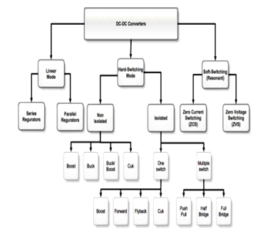 Figure 13 (a): DC-DC Converters Overview (adapted from [6])
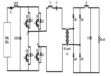 Figure 13 (b): Methodology to Design FC Based Power Converters Systems: A Resonant Approach (adapted from [6])
2.14. Design and Control of a 6-phase IBC Based-on SiC Semiconductors with EIS Functionality for Fuel Cell Electric Vehicle
Researched by [20] indicates that, in today’s FC Electric Vehicle (FCEV), DC-DC converter is paramount to step-up the PEM FC output voltage to a high level (400 – 700V). As a result, the research aim was to design a 6-phase IBC based on SiC semiconductors and inverse coupled inductors of cyclic cascade structure having high compactness, high efficiency and high voltage gain ratio. The reliability and durability have to be enhanced to advance the consumption and commercialization of FC technologies. Electrochemical Impedance Spectroscopy (EIS) is typically used for PEM FC’s diagnosis. To eliminate additional equipment and sensor, the on-line EIS detection functionality incorporated with the control technique of the suggested PEM FC linked to the DC-DC step-up converter was also investigated. The interleaved topology helped decreased the FC current ripple to ensure an extended FC lifespan. Furthermore, the multi-phase topology shared the high input current, hence reducing Joule heating, which allays the electrical stress of the power switches; thus, this redundancy ensures the reliability and robustness of the converter. The magnetic core design is also critical, as it controls the amount of ripple; as a result, the three types Uncoupled (UC)-IBC, Direct Coupled (DC)-IBC, and Inverse Coupled (IC)-IBC were experimented. The SiC-based semiconductors increased the switching frequency and decreased power losses. The on-line EIS detection functionality was integrated with sliding mode control (SMC) of the postulated DC-DC step-up converter. Fuel cells most common problems of membrane drying and flooding were estimated based on PEM FC’s equivalent electric circuit model. The real-time hardware-in-the-loop (HIL) validation of the proposed converter was achieved. MicroLabBox (embedded real-time processor with (Field Programmable Gate Array (FPGA)), was used as the real-time platform for prototyping. In all, a 21kW PEM FC’s voltage model was developed as the power source and the HIL framework provided in real-time − a benefit to monitor the converter’s dynamic working process that was not viable with the offline simulation.
 Figures 14a-14c summarize the study.
Figure 14: Six-phase IBC Based on SiC Semiconductors with EIS
(adapted from [20])
2.15. Design Considerations for DC-DC Converters in Fuel Cells Systems
As examined in [4], the development of alternative energy sources, has been improved by the fast increase of fossil fuel costs along with a rise in environmental education – which include but unlimited to FCs, wind, solar and ocean tidal-wave power. Among them, FCs due to their high modularity, efficiency and basic design have received increased interests in recent years. However, their low voltage output and wide variation from unloaded to fully loaded, demands the need of a power converter to interface the FC to its loads. In light of this, their research was undertaken, in which design considerations were attained analytically and experimentally verified to enable an efficient and stable fuel cell as well as power converter system. Further to the design guidelines, investigated also were new power converter layouts that do not need the use of transformers to accomplish a large voltage gain. The general outcomes are means of i) mathematical analysis and ii) experimental prototypes, that contributed to the lessening of the cost and size of the power converter as well as to raise the efficiency of the system. It was discovered that when the FC load current is not purely DC, the Hydrogen usage of the stack increased and the power output of the FC decreased. This effect importance is a function of the ripple current frequency as demonstrated in their full research.
 (a) Typical fuel cell power conversion system for residential applications
 (b) Block diagram of the proposed DC-DC converter
 (c) Circuit schematic of the proposed two level boost and buck-boost converter
 (d) Proposed sectioned / taped FC stacked with modular DC-DC converter
Figure 15: Design Considerations for DC-DC Converters in FCs Systems (adapted from [4])
Furthermore, by using analytical and experimental methods, it was demonstrated that for load currents with low frequency ripple (<1kHz), the Hydrogen usage increased up to 7% whereas the power output of the FC decreased up to 30%. In addition, if the frequency of the ripple current is high, >20kHz, the Hydrogen utilized by the FC also increased in the range from 1 – 3%, whereas its power output dropped by 5%. It was further realized that the FC thermal performance was not rigorously affected by high frequency ripple currents presence – due to discontinuous operation mode. It was also found that the FC internal impedance can considerably affect the dynamics of the DC-DC converter. Also, the diminished power left during purging of the FC stack has been shown to be another possible cause for instability. To allay these problems, super-capacitors were connected in parallel to the FCs and a method to compute the value of the super-capacitor to attain stability was derived. A 30W boost converter system experimental results confirmed the validity of the suggested solution. Finally, good dynamic behaviour and stability were proven to be feasible with the use of super-capacitors connected to the output of the FCs. To lessen the cost and volume of the system, a high gain transformer-less DC-DC converter was researched – it employed a two level boost and a two level buck-boost converter in cascade to achieve a high voltage gain and low input ripple current, which contributed to lower electromagnetic interference (EMI). Experimental results demonstrated the viability of the DC-DC converter and showed a possible voltage gain of 5. Normally, FCs are constructed by stacking many cells which limit the generated power to the weakest cell in the stack. In addition, if one or more FCs fail, the entire system must be overhauled. To address these shortcomings, a new modular FC stack and DC-DC converter were pioneered – the FC stack was partitioned into different sections with autonomous operations. This has increased system reliability at a reduced output power should a section failed. Additionally, the generated power from the system was optimized by adjusting the drawn current from each section based on the voltage they produced, which resulted in a 10-14% extra power generation. Common mode noise due to transients was also noticed and was resolved by using shielded transformers. Figures 15a – 15d exposit the highlights of the study.
2.16. An Overview of Various Fuel Cell DC-DC Converters
According to [24], fuel cells are now becoming the preferred alternative renewable energy source, as their power production process is not affected by fluctuating environmental factors, contrary to solar cells and wind power plants. However, fuel cells produce low DC output voltage which requires stepping-up and interfacing them to the DC bus. Thus, the need for DC-DC boost power converters, which could be interleaving to help minimize the power ripples as well as bidirectional to charge storage devices such as a battery. In this regard, their paper discussed various interleaved (2, 3, 4 and 6 phases) and bidirectional (non-isolated and isolated) DC-DC boost converters architectures. The non-isolated BDC DC-DC boost converters covered include i) buck-boost converter, ii) cascaded buck-boost converter, iii) CUK converter, iv) SEPIC-ZETA converter and v) switched capacitor. The isolated BDC DC-DC boost converters covered include i) dual half bridge (DHB) and ii) dual active full bridge (DAFB). Figure 16 illustrates the research overview and the conclusion drawn is interleaved boost converters improve power ripples and the more the interleaving, the better the ripple reduction; however, the more costly and bulky it becomes due to the many components used. BDC can additionally charge storage devices and furthermore, the isolated types can offer galvanic protection in high power applications; however, their large size due to the extra isolating transformer, makes them unsuitable for portable and or compact applications.
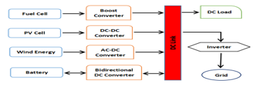 Figure 16: An Overview of Various Fuel Cell DC-DC Converters (redrawn from [24])
2.17. Challenges and Developments of Automotive Fuel Cell Hybrid Power System and Control
As assessed in [25], fuel cells are the future replacement for internal combustion engine in vehicles, though the current costs and Hydrogen supply infrastructure are the limiting factors. In their analysis, they noted that FCs in hybrid power systems have energy control, inertia, power, model and optimization problems which were summarized briefly with emphasis on the electro-chemical reactions, dynamics and the core parameters affecting FCs efficiency and durability. Their review concludes by highlighting that fuel cells have various challenges and the best solution is one that is inclusive by incorporating various hardware and software solutions to optimize fuel cells costs, performance and longevity. Figure 17a exemplifies a typical FC system and Figure 17b illustrates a simplified FCEV architecture.
 (a) Typical fuel cell system
 (b) Fuel cell electric vehicle power-train
Figure 17: Fuel Cell System and FCEV Power-train (adapted from [25])
2.18. Experimental Study and Performance Analysis on High Power Fuel Cell System
In [26], it’s affirmed that PEM fuel cell for use in vehicles requires high power density - normally during starting-up and accelerating. As a result, their study presented an experimental research of a 100kW fuel cell power supply system with focus on measuring the system parameters such as voltage, current, temperature, pressure and hydrogen consumption. Two test set-ups were used; a i) rated and ii) cycle working condition tests. In the former, the system operates for an hour at a rated point with constant working conditions and the outcomes revealed stable operations when working constantly at the rated output power. In the latter, the test is conducted based-on their specified national standard, in which the fuel cell voltage is regulated to be a fixed value and the output current is varied with the working conditions. The conclusion arrived at is the researched fuel cell power engine reached 80kW at rated power with peak power exceeding 100kW. Figures 18a and 18b exemplify the researched FC power schemes.
 Figure 18: (a) The Power System Overview and (b) Fuel Cell Power Engine (adapted from [26])
2.19. Coupled Inductor-assisted Current-Fed Snubber-less Zero-Current-Soft Switching High Step-Up DC-DC Converter for Fuel Cell Power Interface
Presented in [27], is a ZCS current-fed isolated DC-DC boost converter for a fuel cell smart home power system. To avoid ripple current from damaging the fuel cell electrodes and to ensure good boost voltage ratio, their design incorporated a magnetically coupled interleaved inductors with a 180◦ phase shift and a small number of passive components. A 50/60W 1MHz prototype based on 600V GaN-HFETs, was performance tested focusing on the design efficiency, ripple and voltage ratio.
Figure 19a illustrates the concept design and Figures 19b and 19c, portray the DC-DC converter with a full bridge and voltage doubler outputs respectively. Normally, the primary side of the high-frequency transformer (HF-X) windings constitutes a two-phase current-fed high-frequency resonant inverter with complementary Q1 / Q2 as the active switches and L1 / L2 as the coupled inductors. HF-X leakage (Lr) and magnetizing inductances (Lm) produce the multi-resonant transitions with Cp, to generate the high voltage boost ratio and quasi-resonant sub-interval for soft commutations. The leakage inductance operates as a snubber inductor to reduce the high di/dt rate at Q1 and Q2 switched-on transitions. For a higher boost ratio, the full bridge rectifier output can be substituted with a voltage doubler rectifier. Their findings showed that the postulated power converter can attain a snubber-less ZCS commutations, a greater voltage boost ratio and low power ripple; making it suited for smart homes use.
 (a) Concept overview
 (b) High step-up dc-dc converter with full-bridge rectifier
 (c) High step-up dc-dc converter with voltage doubler rectifier
Figure 19: System Concept Design and High Step-up DC-DC Converter Types (adapted from [27])
2.20. Survey of DC-DC Non-Isolated Topologies for Unidirectional Power Flow in Fuel Cell Vehicles
Investigated in [28], is an outstanding research on fuel cells power-trains and power converters. Its extensively discussed in details the theoretical and architectural frameworks of fuel cells. Figures 20a and 20b respectively portray in totality a summary of fuel cell types and power electronics converters classifications.
 (a) Fuel cells classification
 (b) Power converters classification
Figure 20: Fuel Cells and Power Converters Classifications (adapted from [28])
2.21. Performance Analysis of PV and Fuel Cell-based Grid Integrated Power System
Studied in [29], is a smart grid power generation system constituting solar cells and solid oxide fuel cells (SOFC) hybrid system as shown in Figure 21a. The SOFC augments the PV system during power outages due to fault and non-sunny periods. Alternative to SOFC; biomass and wind power systems can be used by integrating them with phase lock loop (PLL) to maintain a constant output supply. The power electronics made used of a DC-DC converter, a three phase DC-AC inverter for interfacing to the electrical grid and AC loads. In addition, is a LC filter to eliminate unwanted signals in the power system. The energy management techniques used include P&O MPPT as well as reference frame theory and PLL to enable a reliable power supply. Figures 21b – 21c respectively show the PV and SOFC schemes.
 (a) Concept overview
 (b) Solar cell power system modeled with Matlab
 (c) Fuel cell power system modeled with Matlab
Figure 21: System Concept Design, PV and Fuel Cell Power Systems Depictions (adapted from [29])
2.22. Modeling and Simulation of DC-DC Converters for Fuel Cell Systems
Affirmed in [30], FC is the future renewable energy source, especially for portable applications. Fuel cells as a result of their low output voltage, require highly efficient power converters; thus, their research using MatLab, focused on the modeling and simulations of four types of DC-DC converters, namely i) boost, ii) SEPIC, iii) LUO and iv) ZETA. Their study was tested using the same fuel cell output voltage of 12V, connected to each converter input with each converter output voltage set at 48V. It was found that the ZETA topology offers the best total harmonic distortion (THD), followed by LUO, SEPIC and Boost with respective THD of 31.22%, 53.83 %, 65.38 % and 80.22 %. It was furthermore concluded that the ZETA topology THD performance can be improved with the addition of more filtering components. Figures 22a – 22c exemplified the SEPIC, LUO and ZETA DC-DC power converters modeled using Matlab Simulink.
 (a) Fuel cell with SEPIC DC-DC converter simulation model
 (b) Fuel cell with LUO DC-DC converter simulation model
 (c) Fuel cell with ZETA DC-DC converter simulation model
Figure 22: Simulink Model of FC with SEPIC, LUO and ZETA DC-DC Power Converters Topology (adapted from [30])
2.23. Smart Fuel Cell Module (6.5 kW) for a Range Extender Application
Researched in [31] using SolidWorks, is a 6.5kW fuel cell model with a mechanically integrated 6-phase interleaved DC-DC boost converter for electric vehicles applications. The design constraints were such that the power converter was mounted on the fuel cell terminal plates and cooled using the same FC cooling system as shown in Figures 23a and 23b. The choice of the power converter topology was driven by the simplicity of its design, since the converter must fit on the FC terminals as well as the fuel cell configuration. As a result, the classic boost converter was chosen, as it employed the minimal components count and furthermore the phase inductors and switching devices can be respectively connected directly on the FC positive and negative plates as pictured in Figure 23b. Continuous conduction mode was chosen for the converter and the ripple was minimal.
To conclude their study, the measured converter efficiency was >95% for a minimum output power of 1.5kW and output voltage of 240V. Future work for an aircraft use was considered.
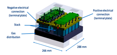 (a) Fuel cell concept design modeled with SolidWorks
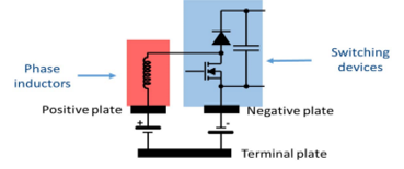 (b) Integration of the power converter on the fuel cell plates
Figure 23: SolidWorks Model of the FC with Integrated Power Converter (adapted from [31])
2.24. Power Converter Topology for Conditioning a Fuel Cell Battery Voltage
Stated in [32], their research conditioned the output voltage of a FC battery using DC-DC boost converter. The main novelty was to substitute the classic boost converter inductor (L) with a inductor-capacitor-inductor (LCL) filter topology as shown in Figure 24. The output voltage was then controlled using a sliding mode strategy including a load impedance observer. The simulated results showed good performance with varying loads.
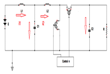 Figure 24: LCL Boost DC-DC Power Converter (adapted from [32])
2.25. Modeling and Simulation of an Aerodrome Electrical Power Source Based-on Fuel Cells
Examined in [33], reducing fuel usage and emissions such as NOx , is aviation present challenge. As a result, there is the need to develop latest power sources using non-polluting sources such as Hydrogen fuel cells. Their work presented the modeling and simulation of a potential configuration for a hybrid aerodrome fuel cell power source. Their postulated architecture consists of a fuel cell stack, DC to DC set-up converter, super-capacitor and a buck-boost converter. The fuel cell and super-capacitor are respectively connected to a boost and buck-boost converter as correspondingly shown in Figures 25a and 25b. With this set-up, the fuel cell with slower power dynamics, supplies the bulk of the power during steady state operation, whereas the super-capacitor with a faster power dynamics, assist the fuel cell during peak power transient demand as well as stores power from the DC bus. The suggested configurations were simulated using MatLab, Simulink and Simscape Power Systems and it can be summed that the hybrid power aerodrome source shown in Figure 25c, can work efficiently, enabling its use for such long-term applications.
 (a) Fuel cell with boost DC-DC converter
 (b) Super-capacitor with buck-boost DC-DC converter
 (c) Fuel cell and super-capacitor with boost and buck-boost DC-DC converters
Figure 25: Hybrid Fuel Cell and Super-capcitor Power System with Respective Boost and Buck-boost DC-DC Converters (adapted from [33])
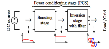
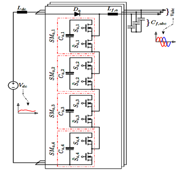
2.26. Current-fed Modular Multilevel Converter (CMMC) for Fuel Cell and Photovoltaic Integration
Indicated in [34], is a CMMC single-stage solution to interface a low voltage photovoltaic and fuel cells DC power supplies to a higher voltage AC load and or grid. Usually, power conditioning stage (PCS) in the form of modular multilevel converters, have been used in various low to high voltage applications with good results; however, their two-stage configuration makes them bulky, hence the need for CMMC - whereby the boosting capability is integrated within the inversion, making it a single-stage DC-AC converter / inverter with additional redundancy and modularity. This enables it use in low voltage applications, where low voltage MOSFETs with low ON-state resistance can be used to increase the power conversion efficiency. A 10kW three-phase CMMC using PLECS, was simulated to verify its functionality. Figures 26a and 26b depict the traditional two-stage DC-AC using (a) a boost converter before the inversion and (b) a step-up transformer after the inversion. Figure 26c exemplifies the single-stage CMMC.
 (a) Two-stage DC-AC with boost converter before the inversion
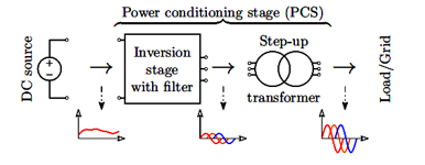 (b) Two-stage DC-AC with step-up transformer after the inversion
 (c) Single-stage DC-AC three-phase CMMC with four sub-modules per phase
Figure 26: Two-stage Traditional and Single-stage CMMC DC-AC Inverters (adapted from [34])
2.27. Novel Four-Port DC–DC Converter for Interfacing Solar PV–Fuel Cell Hybrid Sources with Low-Voltage Bipolar DC Micro-grids
Presented in [35] is a bipolar DC micro-grid (BDCMG) power supply system based on a novel 4-port dual-input dual-output DC-DC converter to interface fuel cells, PV and wind power sources to a low voltage BDCMG. Usually, a BDCMG requires several traditional DC-DC power converters to supply power to the BDCMG poles; however, their researched model in addition to being reliable and efficient, is also compact and unidirectional. It can also function as a single-input dual-output converter as well as with two degrees of freedom using its two switches. Furthermore, the duty cycle changes has no effects on the converter dynamic model; thus, the converter can be controlled with just one controller in different modes, making it less complex. By deriving a small signal model for each operating mode, the converter control system was designed. MPPT was used to track the PV voltage and inductor current without needing an extra PV sensor. Its steady and dynamic states operations were validated using close and open loops results. In-lined with both simulations and theoretical analyses, they observed that the 24V pole voltage and the photovoltaic power are maintained under different conditions (such as during solar irradiation fluctuations and transient load power demands); thus, validating the converter design performance and reliability. The converter was found to have a 93% peak efficiency and ~87% rated power efficiency. Figure 27a exemplifies the proposed BDCMG power scheme and Figure 27b depicts the converter topology whereas Figure 27c shows a different load configuration.
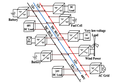 (a) Low-voltage (48-V) BDCMG system.
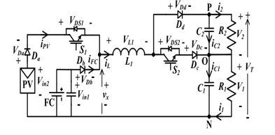 (b) Converter topology
 (c) Converter topology with alternative load representation
Figure 27: BDCMG System and Converter Topologies (adapted from [35])
2.28. Study on Boost Converters with High Power-Density for Hydrogen-Fuel-Cell Hybrid Railway System
Investigated in [36] is a high power hybrid hydrogen fuel cell railway system portrayed in Figure 28a − with focus on designing an efficient and high power density DC-DC converter, since fuel cells are normally low DC power sources and can not supply the needed 1500V to drive the inverter input needed for the railway traction AC motors. Therefore, two DC-DC power converters, namely the interleaved boost converter shown in Figure 28b and the three-level boost converter depicted in Figure 28c, were researched to determine the most suitable DC-DC boost power converter architecture. Taking into considerations and also using optimal design methods were the boost inductor, output capacitor and power semiconductor devices performances with respect to the hybrid railway specifications. Both power converters designs were verified with a 600V input and 1200V / 20kW output setup and the results concluded that the three-level boost converter performed better in-terms of the efficiency, power density and dynamic current response. As a result, it was chosen as the most suitable topology for the hybrid hydrogen fuel cell rail system.
 (a) Propulsion system for hybrid hydrogen-fuel-cell railway system
 (b) High step-up DC-DC interleaved boost converter (IBC)
 (c) High step-up DC-DC three-level boost converter
Figure 28: Concept Design with High Step-up DC-DC IBC and Three-level Boost Converter (adapted from [36])
Table 1 summarizes the fuel cells power converters studies reviewed − in which the major highlights, advantages and disadvantages of each where applicable, are briefly recapitulated.
Table 1: Power Converters Studies Examined Summary (adapted from [1])
| Power Converters | Highlights, Merits and Demerits |
| Study 2.1
(A. Kolli et al, 2015) [23] |
Various FCs DC-DC power converters setups. Emphasis on different types of interleaved converters for high, medium and low power uses. FCs in parallel /series raise output power. |
| Study 2.2
(M. Kabalo et al, 2010) [13] |
FC vehicles cutting edge DC-DC converters. High voltage ratio, compactness and efficiency with affordability, should be used to implement power converters. Presented different schemes. |
| Study 2.3
(M. Delshad & H. Farzanehfard, 2011) [14] |
ZVS current fed push-pull DC-DC converter. When power is off, voltage surge across the switch is absorbed. This improve its efficiency and compactness to enable basic PWM control. |
| Study 2.4
(N. Bizon, 2011) [15] |
A new architecture of FC HPS for efficient functioning and better steadfastness. HPS with active MPPT and hysteretic current controls were used to minimize ripple current from FC. |
| Study 2.5
(O.A. Ahmed & J.A.M. Bleijs, 2013) [16] |
For an UC in DC micro-grids, a bidirectional voltage-fed setup is preferred for quick dynamic response, though for a broad input voltage instability at the UC, there is greater circulating power flow and conduction losses. |
| Study 2.6
(A. Carvalho et al, 2011) [19] |
Modeled a PEM FC using MatLab. Noted the preferred model must take control and optimise the FC operation points. Soft switching based on series resonant and SA was used, as it reduces switching losses and boost efficiency. |
| Study 2.7
(F.M. Mwaniki, 2014) [11] |
Multi-phase tapped-coupled inductor suited for varying high power DC-DC converter uses. Showed minimal input & output power ripples. |
| Study 2.8
(Y. Huangfu et al, 2015) [10] |
High power efficiency step-down converter for discrete wind power supply scheme, akin PV. Achieved a 2kW supply with 96% efficiency with step-down ZVS/LCD scheme with MPPT. |
| Study 2.9
(R. Seyezhai et al, 2013) [9] |
Interleaved converters with switched capacitor are considered the suitable topology for FC systems, because of reduced ripple power in the input and output, quicker transient reaction, small EMI, enhanced efficiency and reliability. |
| Study 2.10
(M. Nymand & M.A.E. Andersen, 2008) [8] |
A new low-leakage inductance low-resistance design approach to low-voltage high-power isolated boost converters. Poorest efficiency at minimum input voltage with maximum power was ~97%. The maximal efficiency was ~98%. |
| Study 2.11
(B. Eckardt et al, 2005) [12] |
FC automotive power-train application using high current buck-boost DC-DC converter with digital control to render apt protection against over-current, over-voltage & over-temperature. |
| Study 2.12
(A. Kirubakaran et al, 2009) [3] |
PEM FC setup with DC-DC step-up converter: Design, modeling and simulation. For instant load fluctuation from 0.6 – 1.1kW, the FC current and voltage took ~50 – 70ms (fuel starvation) to attain a new steady state. The altering voltage was tracked with PI controller. |
| Study 2.13
(M.T. Outeiro & A. Carvalho, 2013) [6] |
A method to devise power converters for fuel cell rooted schemes using resonant technique. Independent voltage and PEMFC controllers. Enhanced FC efficiency by managing FC Pout. |
| Study 2.14
(H. Wang, 2019) [20] |
Devise and management of a 6-phase IBC rooted in SiC with EIS functionality for FC HEV. IBC dynamic model with HIL real-time. |
| Study 2.15
(L.M.P. Fanjul, 2006) [4] |
Design deliberations for DC-DC converters in FC schemes. Used analytical and experimental schemes to achieve a steady and efficient FC & power converter system. A modular FC stack and DC-DC converter were pioneered by dividing it into autonomous optimal sections. |
| Power Converters | Highlights, Merits and Demerits |
|
Study 2.16 (D. Ravi et al, 2018)
[24] |
IBC and BDC were researched. IBC improves power ripples. The more the interleaving, the better the ripple reduction; though, the more costly. BDC can charge storage devices and furthermore, the isolated types offer galvanic protection in high power uses; however, their large size makes them unfit for portable uses. |
| Study 2.17
(J. Gao et al, 2019) [25] |
FCs have various challenges and the best solution is one that is inclusive with various hardware and software solutions to optimize better FCs costs, performance and longevity. |
| Study 2.18
(H. Liu et al, 2020) [26] |
Investigated a high power fuel cell system. Two test setups were used; a i) rated and ii) cycle working condition tests and found that fuel cell power engine reached 80kW at rated power with the peak power exceeding 100kW. |
| Study 2.19
(R. Miyazaki et al, 2020) [27] |
A current-fed snubber-less ZCS FC high step-up DC-DC converter was studied. It achieved a greater voltage boost ratio and low power ripple, making it suitable for smart homes use. |
| Study 2.20
(M.S. Bhaskar et al, 2020) [28] |
Reviewed extensively and comprehensively in theory and topologically, the different types of fuel cells with focus on the use of fuel cells in FCEV power-trains. Miscellaneous types of power converters were also assessed in details. |
| Study 2.21
(K.S. Rathode et al, 2019) [29] |
Researched a hybrid PV and FC system. The power electronics used a DC-DC converter, a three phase DC-AC inverter for interfacing to the electrical grid and AC loads with P&O MPPT as well as reference frame theory and PLL to enable a reliable power supply system. |
| Study 2.22
(S. Kavyapriya & R.K. Kumar, 2020) [30] |
Modeled and simulated four step-up power converters schemes. Found that the ZETA topology offers the best THD, followed by LUO, SEPIC and Boost with THD of 31.22%, 53.83 %, 65.38 % and 80.22 % respectively. |
| Study 2.23
(P. Bazin et al, 2020) [31] |
Implemented a smart FC with built-in DC-DC power converter. The classic boost converter with 6-phase interleaving was chosen, as it fitted well, efficient & offered least parts used. The efficiency was >95% for a nominal output power of ~1.5kW and output voltage of 240V. |
| Study 2.24
(A. Gonnet et al, 2019) [32] |
Studied power converter topology for FC battery voltage conditioning. The classic boost converter inductor was replaced with a LCL filter. Gave good performance at varying loads. |
| Study 2.25
(J. Corcau et al, 2019) [33] |
Modeled & simulated a hybrid aerodrome FC power source consisting of a FC stack, a boost and buck-boost DC to DC converters as well as super-capacitor to provide clean, stable, peak power and energy dynamics during transients. |
| Study 2.26
(A. Abdelhakim & F. Blaabjerg, 2020) [34] |
Proposed a CMMC single-stage solution to interface a low voltage PV and fuel cells DC power supplies to a higher voltage AC load or grid. This offers better performance and is less bulky, contrary to a two-stage boost converter. |
| Study 2.27
(P. Prabhakaran & V. Agarwal, 2020)
[35] |
Presented a BDCMG power supply system based on a novel 4-port dual-input dual-output DC-DC converter to interface fuel cells, PV and wind power sources to a low voltage BDCMG. The converter was reliable, compact, versatile and unidirectional with a 93% peak efficiency and a ~87% rated power efficiency. |
|
Study 2.28
(H.S. Youn et al, 2020)
[36] |
Investigated a high power hybrid hydrogen FC railway system with focus on designing an efficient and high power density DC-DC converter. Two DC-DC power converters, namely the IBC and three-level boost converter were researched to determine the most suitable DC-DC boost power converter architecture. The three-level boost converter out performed the IBC in terms of efficiency, power density and dynamic current response and was chosen. |
3. Energy Management Systems / Storage (EMSs)
In [37]-[70], EMS simply deals with the partial or overall management / control of a device, a section or the entire system – that is, from when, where and how the energy / power is generated, used, processed, converted and or stored. Furthermore, some housekeeping such as thermal management is carried-out as well. The management performed could be i) on-demand (upon users requests or executions as per system dynamics dictates), ii) on-schedule (pre-programmed to do certain routine tasks at a particular time) and iii) artificial intelligence (based-on machine learning). Usually, a dedicated microcontroller and or power management chip or an adequate computing platform is used to optimally process and execute advanced control algorithms that i) manages power generation devices (fuel cells, solar-cells, wind-farms, TEGs, etc) and supporting systems (water pumps or fans), ii) manages power conversion switching devices (switch ON and Off or pulsing the power ICs or MOSFETs or IGBTs etc as required), iii) monitoring energy storage devices (batteries, super-capacitors / ultra-capacitors etc), iv) controlling the end user applications (e.g. HEV) and finally v) housekeeping (temperature monitoring, timestamp etc) and interacting with the system processes optimally to ensure the closed loop power generation / energy conversion and storage processes are efficient, affordable, quicker, safer and reliable. Examined in what follows are some case studies on power and energy conversions management schemes applicable to FCs and suitable for FC CCHP systems.
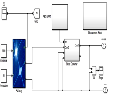
3.1. MIL, SIL and PIL Tests for MPPT Algorithm
Investigated by [37], a boost converter is necessary to convert DC voltage to another DC voltage (DC-DC). In their research, solar energy was harvested by PV array and tracked for continuous power generation using model based MPPT technique. The converter contained a MOSFET as the converter switch, which is managed by PWM signal. Once the MOSFET switch is ON, the energy from the PV module is stored in the inductor and the reverse biased diode disengages the output from the PV generator while the output capacitor supplies current to the load. Conversely, when the MOSFET switch is OFF, the inductor is in a discharge state and forward biases the diode to engage the output to the PV generator. The PV panel voltage and inductor voltage (discharging state) combine to give the output voltage, which is always more than input voltage, hence boost conversion. The study was systematically performed in three stages as follows i) model-in-the-loop (MIL), ii) software-in-the-loop (SIL) and iii) processor-in-the-loop (PIL) as depicted in Figure 29 − in which an algorithm with customized variable step was modeled and connected to a simulated PV panel and a boost converter. The MPPT model was simulated first using Simulink and the process is called MIL as shown in Figure 29. The result acquired using MIL test under STC was asserted in the study and as presented in the steady state, the PV power is equal to 60.54W which is the highest power of the Solarex MSX-60 panel under STC (1,000W/m² and 25°C). The study first demonstrated the MIL test result when the irradiance was raised from 500 to 1000 W/m², then reduced to 800W/m² and finally to 600W/m² − the tailored algorithm gave quicker response during irradiance changes and the steady-state oscillations were almost negligible.
The algorithm was changed from MIL format to SIL and the same irradiance test pattern repeated again to test the MPPT tracking and the same result was achieved similar to that of MIL.
Finally, the code was changed to PIL format and the same irradiance test pattern repeated again to test the MPPT tracking using hardware-in-the-loop as illustrated in Figure 29, which also gave the same result. This concludes that the implemented MPPT algorithm is accurate, as all the three algorithm formats gave the same outcomes. This approach can be applicable also to fuel cells.
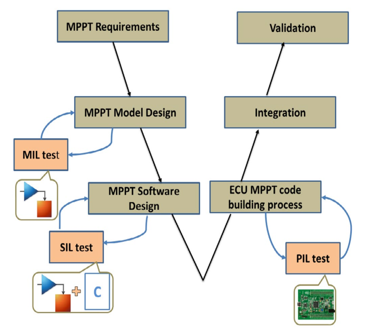 Figure 29: MIL, SIL and PIL Tests for MPPT Algorithm (adapted from [37])
3.2. Review on EMS for FCs Hybrid Electric Vehicle: Issues and Challenges
According to [38], different ways of using a battery to supplement a fuel cell to reliably supply power without experiencing the fuel cell fuel starvation phenomenon were investigated. The basic rationale in the literature was to formulate various types of power converters and energy management systems / storage (EMS) governed by different control strategies − which include but not limited to the followings techniques a) fuzzy logic [39], b) power frequency splitting [40], c) space dynamic equation, d) deterministic dynamic programming [41], e) neural network optimization algorithm [42], etc.
Furthermore in [38], super-capacitor (SC) instead of a battery, was used to supplement a fuel cell. Super-capacitors are known to have very high power density (relative to a battery or FC), enabling it to react faster in transient conditions of brief high current demand. This method requires as well various topologies of power converters and EMS governed by different control techniques, which include but unlimited to the following methods a) differential flatness controls [43], b) polynomial control technique [44], c) wavelet-based load-sharing algorithm [45], d) fuzzy logic [46], e) wavelet adaptive linear neuron (WADALINE) [47], f) adaptive optimal control algorithm (AOCA) [48], etc.
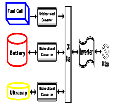 Figure 30: Fuel Cell, Battery and Ultra-capacitor Hybrid Power System (redrawn from [38])
Finally, the third setup as stated in [38], involves all three – the FC, battery and finally the super-capacitor all connected in parallel. This setup requires as well various topologies of power conversion and EMS governed by different control methods, which include but unlimited to the following approaches a) proportional integral (PI) regulator [49], b) fuzzy logic [50], c) various FC, battery and SC configurations [51], d) traction control method [52], e) flatness control technique [53], f) PWM control [54], state machine strategy [55] PI and nonlinear sliding mode controllers [56] etc. The fuel cell, battery and super-capacitor technique is the most effective and widely used, as it provides both high energy and high power densities, as well as storage when needed. Figure 30 summarily depicts this technique.
3.3. A Comparative Study of EMS Schemes for a FC Hybrid Emergency Power System of More-Electric Aircraft (MEA)
Researched in [57], an articulation of assorted EMS for a fuel cell-based emergency power system of a More-electric aircraft was presented. Akin to Figure 30, the fuel cell hybrid system comprises of a FC, Li-ion battery and super-capacitor, together with DC-DC converters and DC-AC inverter as shown in Figure 31. The EMS techniques comparatively studied include those used in FC vehicle applications such as the proportional integral (PI), the state machine, the fuzzy logic /frequency decoupling, the equivalent consumption minimization and the rule-based fuzzy logic strategies. The main metrics used to compare the various EMS strategies performance are the i) the H2 consumption, ii) state of charge of the batteries / super-capacitors and iii) general system efficiency. Lastly, a novel technique using the wavelet transform of their instantaneous power, was used to measure the tensions on each energy source to determine the impact on their life cycle. Simulation models as well as an experimental test setup were developed to simulate and practically verify the study.
 Figure 31: Hybrid Fuel Cell, Battery and Super-cap with EMS (adapted from [57])
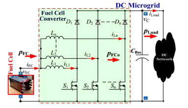
3.4. Model-Free Control of Multi-phase IBC for FC / Reformer Power Generation
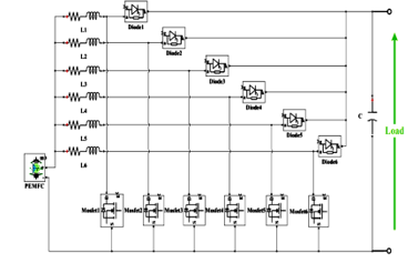
Fuel cells require power converters to boost their low DC output voltage, as well as a control mechanism to optimize its operation. According to [58], the regulation parameters are set using a linear method to assess the convergence problem; as a result, they developed further a model free control (MFC) to manage the fuel cell power for DC micro-grid applications. In their approach, a 2-phase interleaved boost converter was implemented to address the non-linear control problem. Relative to PI and flatness control techniques, a MFC is simple and don’t need precise info of the DC micro-grid parameters, though MFC still needs to know the power converter inductances value. The simulated design was done using dSPACE MicroLabBox and practically tested using a 50V 2.5kW PEMFC with two 2.5kW converters connected in parallel to the FC output and both tests correlated with excellent performance. Figure 32a depicts the FC power plant overview and Figures 32b and 32c respectively represent the IBC architecture and a two-phase MFC technique.
 (a) FC / reformer power plant for grid connected applications
 (b) Multi-phase parallel IBC for FC applications
 (c) Suggested MFC of the FC power for the multi-phase FC power converter
Figure 32: FC Power Plant, Power Converter and MFC (adapted from [58])
3.5. Control and Grid Connection of a FC Power System
As now known, FC is gaining traction in micro-grids and other applications due to their environmental friendliness. Studied in [59] is 900 cells (0.7V per cell) 625V PEMFC stack connected to a 3-phase electrical network using a 700V DC-DC conventional boost converter and a 420V voltage source converter (VSC) DC-AC inverter. PI linear controllers are used in the power converter to monitor the voltage/current and to regulate the electrical dynamics needed to reliably supply power to the grid. The VSC regulates autonomously the active and reactive powers injected to the grid, using two linear control loops PI(1) and PI(2) and a sinusoidal pulsed width modulation (SPWM) scheme. MatLab / Simulink was used to model and simulate the design and the PI controller could reach steady state within 50ms. The VSC inverter controller was able to reach steady state within 30ms when the active and reactive powers were doubled. Figure 33a illustrates the FC electrical network and Figures 33b and 33c, respectively denote the PI and VSC controllers strategy.
 (a) The fuel cell stack, power converter and 3-phase grid
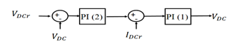 (b) The boost converter PI controller sketch
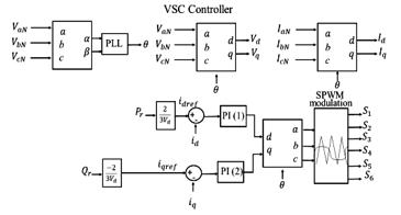 (c) The VSC control and modulation strategy
Figure 33: The FC, Power Converter and Electrical Grid with PI and VSC Controllers Schemes (adapted from [59])
3.6. A Novel Control Scheme for High Efficiency FC Power Systems in Parallel Structure
Discussed in [60] is a basic control technique for greater efficiency power converters of a FC distributed generation (DG) system shown in Figures 34a-34c. Usually, multiple FCs and power converters are connected in parallel to meet the power rating required for a FC DG systems. However, power systems have three main losses; namely core, switching and conduction losses − the switching and core losses are insensitive to load fluctuations, whereas the conduction loss is proportional to power output. Therefore, when power systems work under light-load conditions, the switching and the core losses can significantly contribute to the total losses, as the conduction loss will be small. As a result, the traditional paralleling approach entails the power system operates the same irrespective of the load size, making the power system in-efficient at light-load (small current) conditions, due to the predominantly switching and core losses. Therefore, the parallel system efficiency under light-load is enhanced by changing accordingly the quantity of parallel power units to meet just the light-load demand − doing so substantially reduce the switching and core losses, as less power units will be operating and more can be added under heavy-load. Three 300W units were paralleled to achieve a 900W FC DG efficient system.
 (a) Parallel FC DG system
 (b) Current-fed isolated full-bridge power converter
 (c) Proposed control scheme block diagram
Figure 34: The Proposed FC System, Power Converter and Controller Scheme (adapted from [60])
3.7. An EMS Strategy Based-on State Machine with Power Compensation for PV-PEMFC-Li-ion Battery Power System
Investigated in [61] is a hybrid power supply system constituting a PEMFC, PV and auxiliary Li-ion battery for electric vehicles as exemplified in Figure 35a. A conventional FC and solar cell DC-DC boost converters are used and for a Li-ion battery, a boost-buck power converter is employed. To efficiently coordinate the different power / energy sources and stabilize the DC bus voltage, a state machine EMS control technique with power compensation was employed. The rationale is to minimize the frequency of the PEM FC power output variations and ensuring the Li-ion battery charges and discharges within the ideal intervals. Figure 35b illustrates the state machine EMS used to adjust the FC voltage and Li-ion SoC to attain optimal results.
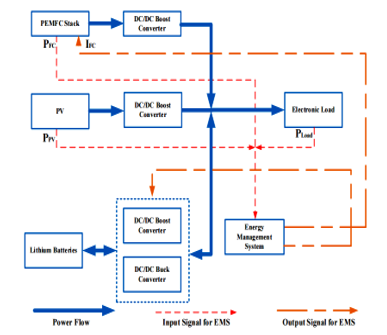 (a) FC, TV and Li-ion Power System Overview
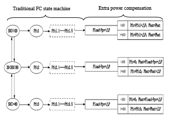 (b) Optimized FC state machine EMS with power compensation
Figure 35: Proposed Power System and State Machine EMS (adapted from [61])
3.8. Development of a Fuzzy-Logic-Based EMS for a Multi-port Multi-operation Mode Residential Smart Micro-grid
Demonstrated in [62] is an advanced grid-tied residential smart micro-grid composing of a fuel cell, solar cell and battery bank to supply the local loads using both electric and magnetic buses. Typically, an electric bus comprising of multiple converter based micro-grids is used; however, this setup is costly and bulky with numerous and large conversion stages; thus, the addition of a common magnetic bus with multi-port converters circumvent these shortcomings and furthermore isolate the conversion ports. Their hybrid architecture with EMS translates to a centralized quicker and versatile system. The suggested micro-grid was capable of working in multiple grid-tied and off-grid modes using a fuzzy logic energy management unit (EMU) controller to choose the proper mode of operation − taking into cognizance short and long-term energy generation and usage. The micro-grid operation performance was enhanced using synchronized bus-voltage balance control technique. The executions of the micro-grid and EMU were experimentally tested for three different cases of the residential load in grid-connected and off-grid modes. The energy distribution and cost analyses for each case show the merits of the EMU for both the grid and user. The various control schemes for each of the power converters/inverters is detailed in the full text. Figure 36 exemplifies and summarizes the research.
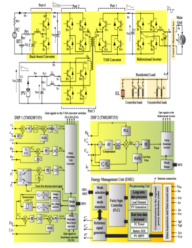 Figure 36: Proposed Smart Micro-grid including Converters, Controllers and EMU (adapted from [62])
3.9. Frequency Separation-based Power Management Strategy for a FC-Powered Drone
Studied in [63] is a hybrid FC and super-capacitor with a DC-DC boost converter power system for drones depicted in Figure 37a. The EMS control technique exploited is routed-in frequency separation-based technique whereby the required power is shared between the energy sources − in this case, the FC and super-capacitor. Depicted in Figures 37b and 37c, the drone flight load profile is divided into low and high frequency components, in which the FC connected to the DC-DC boost converter is controlled to handle the low frequency dynamics whereas the supercapacitor handles the high frequency dynamics during peak power demands as expatiated in Figure 37c. The system was simulated using a real power profile from a small hexacopter experimental flight test and the results justify the EMS was capable of minimizing the fuel cell power variations with the supercapacitor handling all of the transient / peak power demands, consequently prolonging the FC lifetime and drone flight periods.
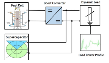 (a) Drone FC and super-capacitor power system overview
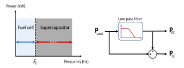 (b)Frequency power sharing concept
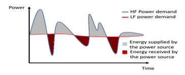 (c)Power frequency sharing
Figure 37: Proposed Drone Hybrid Power System and Frequency Separation EMS (adapted from [63])
3.10. MPPT Control of an IBC for a PEM FC Applications
Stated in [64] is simply how FC power can be stepped-up using a four-phase IBC and controlled efficiently using a MPPT P&O EMS. The IBC further reduced the FC voltage and current ripples whereas the MPPT ensured max power is extracted from the fuel cell. Figures 38a-38c summarize the implementation.
 (a) Four-phase IBC Simulink model
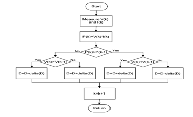 (b) Perturb and Observe MPPT
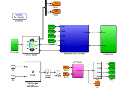 (c) IBC with MPPT Simulink model
Figure 38: FC and Four-phase IBC with MPPT P&O EMS (adapted from [64])
3.11. Power Flow Control via Differential Power Processing to Enhance Reliability in Hybrid Systems based on PEM FC
Presented in [65] is an interesting study on interconnecting fuel cells to obtain maximum output power. Two interconnection techniques; namely, i) modular integrated converter (MIC) and ii) differential power processing (DPP) including their power converters (synchronous switching bidirectional buck-boost) and EMS technique (MPPT P&O / Hill Climbing (HC)) were modeled using Matlab and discussed in details. As depicted in Figure 39a, the MIC topology has each FC connected in parallel to its own separate converter and each converter is in turn connected in series. This allows several converter topologies and control schemes to be implemented independently. However, the main disadvantages are the number of converters used, the cost involved and poor conversion efficiency − as 100% of the power produced by each FC sub-module is processed. As displayed in Figure 39b, the DPP architecture simply has two FCs connected in parallel with a single buck-boost converter, thereby reducing the total number of power converters by one. Further advantages include simplicity, speed, affordability and improved efficiency − since only a fraction of the FC sub-module generated power is processed. However, the main disadvantage is the complexity in the control technique implementation, since the active balance needs to communicate with each FC sub-module to apply MPPT.
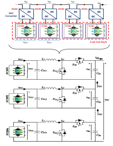 (a) MIC topology showing FCs and converters interconnections
Using Matlab / Simulink, MPPT P&O algorithm illustrated in Figure 39c was implemented on the DPP converter to achieve a fast control loop. The simulation verified the merits of the DPP topology and the MPPT P&O algorithm convergence technique.
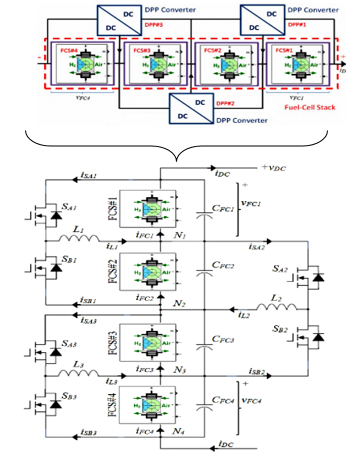 (b) DPP topology showing FCs and converters interconnections
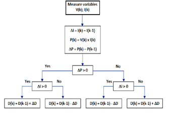 (c) HC / P&O MPPT control algorithm
Figure 39: MIC, DPP and MPPT P&O Techniques (adapted from [65])
3.12. EMS in a Multi-source System using Isolated DC-DC Resonant Converters
Described in [66] is a hybrid FC and super-capacitor with PI controller power system. The research purpose was to develop a control mechanism for the fuel cell and super-capacitor DC-DC resonant power converters to share the system power according to their dynamic responses. Usually, the FC has a slower power dynamic relative to the super-capacitor; therefore, initially the super-capacitor will handle the instant peak power demands whereas the FC provides the bulk of the power during steady state. The isolated LLC resonant converter connects the FC to the DC bus, whereas the super-capacitor connects to the DC bus via the bidirectional resonant converter which charges and discharges the super-capacitor. The modeling and simulations were done using Matlab / Simulink with PLECS and the findings affirm the merits of using resonant converters − which also offer isolation and reduced switching losses. Portrayed in Figure 40a is the FC and super-capacitor hybrid power system and Figures 40b and 40c respectively lucubrate FC and super-capacitor PI controllers.
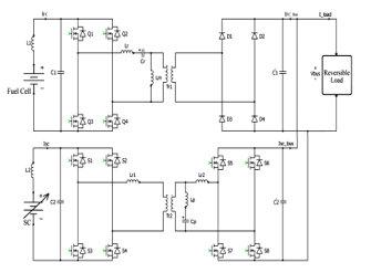 (a) FC and super-capacitor hybrid system
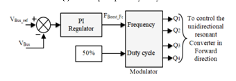 (b) Fuel cell voltage control loop
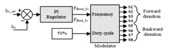 (c) Super-capacitor’s bidirectional control loop
Figure 40: FC, Super-capacitor Hybrid Power System with PI Controller (adapted from [66])
3.13. EMS Optimization for a FC Hybrid Vehicle based on Power Losses Minimization
Indicated in [67], fuel cells hybrid vehicle is a suitable alternative to internal combustion engine vehicles, as they are environmentally friendly. Their research thus proposed an energy management optimization technique for the power distribution system, to increase the driving range of fuel cell hybrid vehicles. The hybrid energy system constitutes a FC connected to a power converter which in turns connects concurrently to a battery and a DC load as represented in Figure 41a. The suggested control optimization algorithm is based on minimizing the energy losses in the system. Using Simulink / PSIM; the losses, costs, size and mass were evaluated, in which it was found that lower FC power and higher battery capacity offer low energy losses and low consumption; whereas maximum fuel cell power and lowest battery capacity provide minimum costs, mass and size. The results correlated other studies in the literature. Figures 41b and 41c depict the basic FC and battery models respectively and Figure 41d shows the optimization algorithm high level overview.
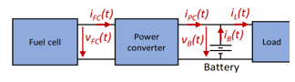 (a) Fuel cell, power converter and battery hybrid power overview
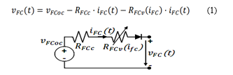 (b) Super-capacitor simplified model
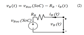 (c) Battery basic model
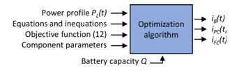 (d) Optimization algorithm input and output data
Figure 41: System Overview, Fuel Cell and Battery Models and Optimization Algorithm Overview (adapted from [67])
3.14. Dynamic Modeling and Closed-loop Control of Hybrid Grid-connected Renewable Energy System with Multi-input Multi-output Controller
Proposed in [68] and summarized in Figure 42a, is the use of multi-input multi-output (MIMO) technique to dynamically model and closed-loop control a hybrid grid-tied renewable energy system. The system constitutes a solar cell and FC each respectively connected to their boost converters which are in turn connected in parallel to a single-phase H-bridge inverter to supply an AC load. The system employed the traditional MPPT and PI control techniques compensated by the MIMO network detailed in Figure 42b. Using the system transfer functions frequency response, the MIMO controller gains are tuned. MatLab and Simulink were used to simulate and analyse the designed MIMO controller accuracy and effectiveness and from the results, MIMO is quick and stable at various functional points, having a negligible steady-state error as well as with a grid THD of ~1.48% in accordance with standards of distribution networks.
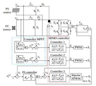 (a) Suggested control structure for grid-connected PV/FC hybrid energy system
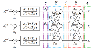 (b) Compensation network
Figure 42: Proposed FC and PV Hybrid Energy System and Compensation Network (adapted from [68])
3.15. FCEVs — A Brief Review of Current Topologies and EMS Strategies
Articulated in [69], advancement in technology and new international policies on electric / hybrid electric vehicles are becoming trendy. In light of this, their research focused on fuel cells and energy storage devices as well as power converters and EMS techniques to sustain hybrid electric vehicle dynamic power demands. Different fuel cell energy / power configurations and power converters topologies were assessed and the highlights are presented in Figures 43a and 43b − respectively a fuel cell with storage devices and dual-input high step-up isolated converter. Furthermore, miscellaneous EMS strategies were examined with focus on energy efficiency, usage of hydrogen and sub-systems decay involved. The pros and cons of rule-based, learning-based and optimisation-based EMS strategies were discussed and the conclusion is to hybridize modern and existing strategies to eliminate the uncertainties regarding EMS techniques robustness.
 (a) FC, battery and ultra-capacitor hybrid electric vehicle configuration
 (b) Dual-Input High Step-Up Isolated Converter (DHSIC)
Figure 43: FC Hybrid Electric Vehicle and DHSIC Scheme (adapted from [69])
3.16. A Review and Research on FCEVs: Topologies, Power Electronic Converters, EMS Methods, Technical Challenges, Marketing and Future Aspects
Analyzed extensively in [70], fuel cells are the future especially for FCEV as shown in Figure 44a. In this respect, a comprehensive study of types of FCs with electric motors are explained with focus on their areas of applications, diagnostic properties and working environments. Furthermore, power converters which boost the FC voltages to drive different motor topologies used in FCEVs, are elaborated based on their structural frequency of use, their architecture and difficulty. Summarized in Figure 44b, assorted FCEVs power converters EMS schemes and technical challenges were examined and the final closing remarks highlighted the present status and future prospects using significant number of marketing and target data.
 (a) FCEV power transmission system with auxiliary power supplies
 (b) FCEVs EMS classification of technical challenges and system problems
Figure 44: FCEV Power Transmission System and EMS Schemes and Challenges (adapted from [70])
Table 2: EMS Case Studies Examined Summary
| EMS Research | Highlights, Merits and Demerits |
| Study 3.1
(S. Motahhir et al, 2017) [37] |
MIL, SIL and PIL tests for MPPT algorithm. Implemented MPPT algorithm on each and all three formats reasonably gave similar results. |
| Study 3.2
(N. Sulaiman et al, 2015) [38] |
Extensive analysis on FC fuel starvation and EMS schemes for FC HEV: In-depth FC issues, challenges & solutions were presented. |
| Study 3.3
(S.N. Motapon et al, 2014) [57] |
Implemented simulated and experimental test frameworks for relative analyses of various EMS methods for a FC hybrid power system. |
| Study 3.4
(P. Mungporn et al, 2019) [58] |
Developed further a model free control (MFC) to manage the fuel cell power for DC micro-grid applications. In their approach, a 2-phase interleaved boost converter was implemented to address the non-linear control problem and the simulated and practical results correlated. |
| Study 3.5
(G.G. Suárez-Velázquez et al, 2020) [59] |
Used VSC to autonomously regulate the active and reactive powers injected to the grid, via a sinusoidal SPWM strategy and two linear control loops PI(1) and PI(2). The VSC was able to reach steady state within 30ms when the active and reactive powers were doubled. |
| Study 3.6
(Y. Jeong et al, 2019)
[60] |
The efficiency of parallel FC systems under light-load is enhanced by changing accordingly the quantity of parallel power units to meet the light-load demand and substantially reduce the switching / core losses. Three 300W units were paralleled to achieve a 900W efficient system. |
| Study 3.7
(Y. Zhang et al, 2019) [61] |
A state machine EMS control technique with power compensation was employed to curb the frequency of the PEM fuel cell power output variations and ensuring the Li-ion battery charges & discharges within the ideal periods. |
| Study 3.8
(M. Jafari et al, 2019)
[62] |
Demonstrated an advanced grid-tied household smart micro-grid consisting of a fuel cell, solar cell and battery bank to provide the local loads using both electric and magnetic buses. The magnetic bus with the multi-port converters augments the electric bus and further isolates the conversion ports. The EMU controller was tested for three distinct scenarios of the home load and the distribution of energy and cost analyses for each case, show the EMU merits. |
| Study 3.9
(M.N. Boukoberine et al, 2020) [63] |
The EMS method used is routed-in frequency separation-based scheme, whereby the required power is shared between the energy sources. |
| Study 3.10
(E.M. Barhoumi et al, 2020) [64] |
FC power can be stepped-up using a four-phase IBC and controlled efficiently using a MPPT EMS scheme to reduce power ripples. |
| Study 3.11
(K.S. Artal-Sevil et al, 2020) [65] |
Presented MIC and DPP connections of FCs with power converters. MPPT was used on the DPP converter to achieve a fast control loop. |
| Study 3.12
(M. Arazi et al, 2020) [66] |
Developed a mechanism for FCs and SCs DC-DC resonant power converters to share the system power using their dynamic responses. |
| Study 3.13
(A. Martin-Lozano et al, 2020) [67] |
Proposed an EMS optimization technique for the power distribution system to increase the driving range of fuel cell hybrid vehicles. The results correlated other studies in the literature. |
| Study 3.14
(M. Salimi et al, 2021) [68] |
Suggested the used of MIMO technique to dynamically model and closed-loop control a FC hybrid grid-tied renewable energy system. |
| Study 3.15
(I.S. Sorlei et al, 2021) [69] |
Used FCs and energy storage devices as well as power converters and EMS techniques to sustain hybrid electric vehicle dynamic power. |
| Study 3.16
(M. İnci et al, 2021) [70] |
Reviewed extensively FC types with electric motors with focus on their uses, diagnostic properties and finally working environments. |
Table 2 summarizes the reviewed EMS FC applicable studies.
4. Conclusion
Energy insecurity and electrical energy in particular, is a progressive pressing societal crisis in South Africa and Africa. In this regard, this article articulated a structural review of forty four different power converters and EMS research case studies to reasonably choose and develop a suitable FC power converter and EMS scheme for a hybrid FC CCHP system for households / commercial applications. From the review, it was observed that the power converters based on IBC / variants and as well isolated boost converters were of interests. IBC are simple, more robust, good for ripples reduction and peak power applications. However, the fundamental IBC topology is not isolated and adding isolation transformers offers protection but increases the costs and size. Likewise, EMS techniques can be grouped under rule-based, learning-based and optimization-based but the most popular EMS strategy used with power converters are the MPPT and PI controller. Furthermore, FCs can also be modularized with each FC sub-module having its own power converters and EMS scheme to increase the system efficiency. In sum, there is no method that is flawless − choosing a particular approach and trading-off different features depend on the targeted applications and the research objectives; whether to maximize efficiency, robustness, safety, performance etc and minimize costs, size, noise, complexity etc. For our research project, power converters based-on IBC variants and BDC with EMS based on MPPT and or PID controller for use with FC, Li-ion battery, ultra-capacitor and thermo-electric devices are considered to investigate further the CCHP system postulated in Figure 45 to conclude the study.
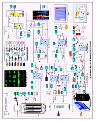 Figure 45: Postulated Fuel Cell CCHP System Undergoing Research
Glossary
AOCA Adaptive Optimal Control Algorithm
BDC Bidirectional DC-DC Converter
BDCMG Bipolar DC Micro-grid
CCHP Combined Cooling, Heating and Power
CMMC Current-fed Modular Multilevel Converter
CPC Conventional Phase-shift Control
CPUT Cape Peninsula University of Technology
DAFB Dual Active Full Bridge
DC Direct Current
DC-IBC Direct Coupled-Interleaved Boost Converters
DG Distributed Generation
DHB Dual Half Bridge
DHSIC Dual-Input High Step-Up Isolated Converter
DPP Differential Power Processing
EGS Energy Generation System
EIS Electrochemical Impedance Spectroscopy
EMI Electro Magnetic Interference
EMS Energy Management Systems / Energy Management & Storage
EMU Energy Management Unit
FCEV Fuel Cell Electric Vehicle
FCS Fuel Cell Stack
FIC Full-bridge Isolated Converter
FLC Fuzzy Logic Controller
FPGA Field Programmable Gate Array
GaN Gallium Nitride
HC Hill Climbing
HF High Frequency
HIC Half-bridge Isolated Converter
HIL Hardware In the Loop
HPS Hybrid Power Source
IBC Interleaved Boost Converters
IC-IBC Inverse Coupled-Interleaved Boost Converters
LF Low Frequency
MFC Model Free Control
MIC Modular-Integrated Converter
MIL Model In the Loop
MIMO Multi-Input Multi-Output
MPPT Maximum Power Point Tracking
PCS Power Conditioning Stage
PEM Proton Exchange Membrane or Polymer Electrolyte Membrane
PI Proportional Integral
PIL Processor In the Loop
PLL Phase Lock Loop
PV Photovoltaic
PWM Pulse Width Modulation
RIC Resonance Isolated Converter
SA Simulated Annealing
SC Super-capacitor
SiC Silicon Carbide
SIL Software In the Loop
SOC State of Charge
SMC Sliding Mode Control
SPWM Sinusoidal Pulsed Width Modulation
TEG Thermoelectric Generator
THD Total Harmonic Distortion
UC-IBC UnCoupled-Interleaved Boost Converters
VSC Voltage Source Converter
WADALINE Wavelet Adaptive Linear Neuron
ZCS Zero Current Switching
ZSI Z-Source Inverter
ZVS Zero Voltage Switching
Conflict of Interest
The authors declare no conflict of interest.
Acknowledgment
The authors thank CPUT and HySA UWC for the funding.
- N.P. Bayendang, M.T. Kahn, V. Balyan, I. Draganov, “CCHP Systems Analysis with Emphasis on Fuel Cells, Thermoelectricity and Power Converters,” 2020 5th International Conference on Smart and Sustainable Technologies, SpliTech 2020, 2020, doi:10.23919/SpliTech49282.2020.9243720.
- S. Vigneshwaran, R. Vijayalakshmi, “High efficiency DC/DC buck-boost converters for high power DC system using adaptive control,” American-Eurasian Journal of Scientific Research, 11(5), 381-389, 2016. doi: 10.5829/idosi.aejsr.2016.11.5.22957.
- A. Kirubakaran, J. Shailendra, R.K. Nema, “The PEM fuel cell system with DC/DC boost converter: Design, modeling and simulation,” International Journal of Recent Trends in Engineering, 1(3), 2009, doi: 01.ijepe.01.01.05.
- L.M.P. Fanjul, Design Considerations for DC-DC Converters in Fuel-cell Systems, PhD Thesis, Texas A&M University, 2006.
- M. Grotsch, M. Mangold, A. Kienle, “Analysis of the coupling behaviour of PEM fuel cells and DC-DC converters”, Energies, 2, 71-96, 2009, doi: 10.3390/en2010071.
- M.T. Outeiro, A. Carvalho, Methodology of Designing Power Converters for Fuel-cell Based Systems: A Resonant Approach, New Developments in Renewable Energy, 2013, http://dx.doi.org/10.5772/54674.
- K. Suh and A.G. Stefanopoulou, “Coordination of Converter and Fuel Cell Controllers,” in Proceedings of the 2005 IEEE International Symposium on, Mediterrean Conference on Control and Automation Intelligent Control, Limassol, Cyprus, 2005, doi: 10.1109/.2005.1467076.
- M. Nymand, M.A.E. Andersen, “A New Approach to High Efficiency in Isolated Boost Converters for High-Power Low-Voltage Fuel Cell Applications,” in 2008 13th Power Electronics and Motion Control Conference, Poznan, Poland, 2008, 127-131, https://doi.org/10.1109/EPEPEMC.2008.4635255.
- R. Seyezhai, R. Anitha, S. Mahalakshmi, M. Bhavani, “High gain interleaved boost converter for fuel cell applications,” Bulletin of Electrical Engineering and Informatics, 2(4), 2013, 265-271, doi: https://doi.org/10.11591/eei.v2i4.192.
- Y. Huangfu, R. Ma, B. Liang, Y. Li. “High power efficiency buck converter design for standalone wind generation system,” International Journal of Antennas and Propagation, Volume 2015, Special Issue: Recent Advances in Theory and Applications of Electromagnetic Metamaterials, http://dx.doi.org/10.1155/2015/751830.
- F.M. Mwaniki, High voltage boost DC-DC converter suitable for variable voltage sources and high power photovoltaic application, MEng Dissertation, University of Pretoria, 2014, http://hdl.handle.net/2263/37320.
- B. Eckardt, M. März, A. Hofmann, M. Gräf and J. Ungethüm, “High Power Buck-Boost DC/DC Converter for Automotive Power-train Application,” in 2005 Official Proceedings of the International Conference of Power Electronics, Intelligent Motion, Power Quality: PCIM 2005 Europe, Nürnberg, Germany, 2005, 685, http://publica.fraunhofer.de/documents/N-46644.html.
- M. Kabalo, B. Blunier, D. Bouquain, A. Miraoui, “State-of-the-Art of DC-DC Converters for Fuel Cell Vehicles,” in 2010 IEEE Vehicle Power and Propulsion Conference, Lille, France, 2010, doi: 10.1109/VPPC.2010.5729051.
- M. Delshad, H. Farzanehfard, “A new soft switched push pull current fed converter for fuel cell applications,” Energy Conversion and Management, 52(2), 917–923, 2011, https://doi.org/10.1016/j.enconman.2010.08.019.
- N. Bizon, “A new topology of fuel cell hybrid power source for efficient operation and high reliability,” Journal of Power Sources, 196(6), 3260–3270, 2011, doi: 10.1016/j.jpowsour.2010.11.049.
- O.A. Ahmed, J.A.M. Bleijs, “Power flow control methods for an ultra-capacitor bidirectional converter in DC micro-grids – a comparative Study,” Renewable and Sustainable Energy Reviews, 26, 727–738, 2013, https://doi.org/10.1016/j.rser.2013.06.021.
- A. Kolli, A. Gaillard, A. De Bernardinis, O. Bethoux, D. Hissel, Z. Khatir, “Design and Control of a High Frequency Six-phase Interleaved DC/DC Converter based on SiC Power MOSFETs for a PEMFC,” in 2015 6th International Conference on Fundamentals and Development of Fuel Cells (FDFC 2015), Toulouse, France, 2015.
- A. Kolli, A. De-Bernardinis, Z. Khatir, A. Gaillard, O. Béthoux and D. Hissel, “Part-load Control Strategy of a 20kW SiC Power Converter for Embedded PEMFC Multi-stack Architectures,” IECON 2015 – 41st Annual Conference of the IEEE Industrial Electronics Society, Yokohama, Japan, 2015, 4627-4632, doi: 10.1109/IECON.2015.7392821.
- A. Carvalho, M.T. Outeiro, MatLab in Model-Based Design for Power Electronics Systems, Engineering Education and Research Using MatLab, 2011, doi: 10.5772/21144.
- H. Wang, Design and Control of a 6-phase Interleaved Boost Converter based on SiC semiconductors with EIS Functionality for Fuel Cell Electric Vehicle. PhD Thesis, UBFC and UTBM, Belfort, France, 2019.
- J.W. Pratt, L.E. Klebanoff, K. Munoz-Ramos, A.A. Akhil, D.B. Curgus, B.L. Schenkman, Proton Exchange Membrane Fuel Cells for Electrical Power Generation On-Board Commercial Airplanes, SAND2011-3119 Unlimited Release Printed, 2011.
- J.L. Casteleiro-Roca, A.J. Barragán, F. Segura, J.L. Calvo-Rolle, J.M. Andújar, “Fuel cell output current Prediction with a hybrid intelligent system,” Complexity, Volume 2019, Special Issue: Advanced Controls in Complex Clean Energy Devices, Subsystems, and Processes, https://doi.org/10.1155/2019/6317270.
- A. Kolli, A. Gaillard, A. De Bernardinis, O. Bethoux, D. Hissel, Z. Khatir, “A review on DC/DC converter architectures for power fuel cell applications,” Energy Conversion and Management, 105, 716-730, 2015, https://doi.org/10.1016/j.enconman.2015.07.060.
- D. Ravi, S.S. Letha, P. Samuel, B.M. Reddy, “An Overview of Various DC-DC Converter Techniques used for Fuel Cell based Applications,” 2018 International Conference on Power Energy, Environment and Intelligent Control (PEEIC), Greater Noida, India, 2018, 16-21, doi: 10.1109/PEEIC.2018.8665465.
- J. Gao, M. Li, Y. Hu, H. Chen, Y. Ma, “Challenges and developments of automotive fuel cell hybrid power system and control,” Science China Information Sciences, 62(5), 2019, doi: https://doi.org/10.1007/s11432-018-9690-y.
- H. Liu, L. Xu, Z. Hu, J. Li, H. Jiang, M. Ouyang, “Experimental Study and Performance Analysis on High Power Fuel Cell System,” IECON 2020 The 46th Annual Conference of the IEEE Industrial Electronics Society, Singapore, 2020, 2031-2035, doi: 10.1109/IECON43393.2020.9254802.
- R. Miyazaki, T. Mishima, C.M. Lai, “Coupled Inductor-assisted Current-Fed Snubber-less Zero-Current-Soft Switching High Step-Up DC-DC Converter for Fuel Cell Power Interface,” 2020 IEEE 9th Global Conference on Consumer Electronics (GCCE), Kobe, Japan, 2020, 797-801, doi: 10.1109/GCCE50665.2020.9291776.
- M.S. Bhaskar, V.K. Ramachandaramurthy, S. Padmanaban, F. Blaabjerg, D.M. Ionel, M. Mitolo, D. Almakhles, “Survey of DC-DC Non-Isolated Topologies for Unidirectional Power Flow in Fuel Cell Vehicles,” in IEEE Access, 8, 178130-178166, 2020, doi: 10.1109/ACCESS.2020.3027041.
- K.S. Rathode, S.K. Sharma, S. Shringi, “Performance Analysis of PV & Fuel cell based Grid Integrated Power System,” 2019 International Conference on Communication and Electronics Systems (ICCES), Coimbatore, India, 2019, 970-975, doi: 10.1109/ICCES45898.2019.9002090.
- S. Kavyapriya, R.K. Kumar, “Modeling and Simulation of DC-DC Converters for Fuel Cell System,” International Journal of Engineering and Advanced Technology (IJEAT), 9(3), 2020, doi: 10.35940/ijeat.C5754.029320.
- P. Bazin, B. Beranger, J. Ecrabey, L. Garnier, S. Mercier, “Smart fuel cell module (6.5 kW) for a range extender application,” 2020 22nd European Conference on Power Electronics and Applications (EPE’20 ECCE Europe), Lyon, France, 2020, 1-8, doi: 10.23919/EPE20ECCEEurope43536.2020.9215856.
- A. Gonnet, S.G. Jorge, C. Busada, J. Solsona, “Power converter topology for conditioning a fuel cells battery voltage,” 2019 Argentine Conference on Electronics (CAE), Mar del Plata, Argentina, 2019, 9-14, doi: 10.1109/CAE.2019.8709157.
- J. Corcau, L. Dinca, I. Adochiei, T. L. Grigorie, “Modeling and Simulation of an Aerodrome Electrical Power Source Based on Fuel Cells,” 2019 E-Health and Bioengineering Conference (EHB), Iasi, Romania, 2019, 1-4, doi: 10.1109/EHB47216.2019.8969870.
- A. Abdelhakim, F. Blaabjerg, “Current-fed Modular Multilevel Converter (CMMC) for Fuel Cell and Photovoltaic Integration,” 2020 IEEE 21st Workshop on Control and Modeling for Power Electronics (COMPEL), Aalborg, Denmark, 2020, 1-6, doi: 10.1109/COMPEL49091.2020.9265695.
- P. Prabhakaran, V. Agarwal, “Novel Four-Port DC–DC Converter for Interfacing Solar PV–Fuel Cell Hybrid Sources With Low-Voltage Bipolar DC Microgrids,” in IEEE Journal of Emerging and Selected Topics in Power Electronics, 8(2), 1330-1340, 2020, doi: 10.1109/JESTPE.2018.2885613.
- H.S. Youn, D.H. Yun, W.S. Lee, I.O. Lee, “Study on Boost Converters with High Power-Density for Hydrogen-Fuel-Cell Hybrid Railway System”, Electronics, 9(5), 771, 2020, doi: https://doi.org/10.3390/electronics9050771.
- S. Motahhir, E.G. Abdelaziz, A. Derouich, “MIL and SIL and PIL tests for MPPT algorithm,” Cogent Engineering, 4(1), 2017, https://doi.org/10.1080/23311916.2017.1378475.
- N. Sulaiman, M.A. Hannan, A. Mohamed, E.H. Majlan, W.R. Wan Daud, “Review on energy management system for fuel cell hybrid electric vehicle: Issues and challenges,” Renewable and Sustainable Energy Reviews, 52, 802–814, 2015, https://doi.org/10.1016/j.rser.2015.07.132.
- D. Xiao, Q. Wang, “The Research of Energy Management Strategy for Fuel Cell Hybrid Vehicle,” in 2012 International Conference on Industrial Control and Electronics Engineering, Xi’an, China, 2012, 931–934, doi: 10.1109/ICICEE.2012.247.
- N. Ouddah, M. Boukhnifer, A. Raisemche, “Two Control Energy Management Schemes for Electrical Hybrid Vehicle,” in 2013 Proceedings of the 10th International Multi-conference on Systems, Signals & Devices (SSD13), Hammamet, Tunisia, doi: 10.1109/SSD.2013.6564135.
- O. Sundstrom, A. Stefanopoulou, “Optimal Power Split in Fuel Cell Hybrid Electric Vehicle with Different Battery Sizes, Drive Cycles and Objectives,” in 2006 IEEE Conference on Computer Aided Control System Design, 2006 IEEE International Conference on Control Applications, 2006 IEEE International Symposium on Intelligent Control, Munich, Germany, 1681–1688, doi: 10.1109/CACSD-CCA-ISIC.2006.4776894.
- C.J. Xie, S.H. Quan, Q.H. Chen, “Multiple Model Control for Hybrid Power System of Fuel Cell Electric Vehicle,” in 2008 IEEE Vehicle Power and Propulsion Conference, Harbin, China, 2008, doi: 10.1109/VPPC.2008.4677527.
- P. Thounthong, S. Pierfedereci, J.P. Martin, M. Hinaje, B. Davat, “Modelling and control of fuel-cell super-capacitor hybrid source based on differential flatness control,” IEEE Transaction on Vehicle Technology, 59 (6), 2700–2710, 2010, doi: 10.1109/TVT.2010.2046759.
- A. Tani, M.B. Camara, B. Dakyo, Y. Azzouz, “DC/DC and DC/ACconverters control for hybrid electric vehicles energy management ultra-capacitors and fuel cell,” IEEE Transactions on Industrial Informatics, 9(2), 686–696, 2013, doi: 10.1109/TII.2012.2225632.
- M. Uzunoglu, M.S. Alam, “Modelling and analysis of an FC/UC Hybrid vehicular power system using a novel-wavelet-based load sharing algorithm,” IEEE Transaction on Energy Conversion, 23(1), 263–272, 2008, doi: 10.1109/TEC.2007.908366.
- D.S. Efstathiou, A.K. Petrou, P. Spanoudakis, N.C. Tsourveloudis, K.P. Valavanis, “Recent Advances on the Energy Management of a Hybrid Electric Vehicle,” in 2012 20th Mediterranean Conference on Control & Automation (MED), Barcelona, Spain, 2012, 896–901, doi: 10.1109/MED.2012.6265752.
- Y. Ates, M. Uzunoglu, O. Erdinc, B. Vural, “A Wavelet-ADALINE Network based Load Sharing and Control Algorithm for a FC/UC Hybrid Vehicular Power System,” in Proceedings of the 2009 International Conference on Clean Electrical Power, Capri, Italy, 2009, 591–94, doi: 10.1109/ICCEP.2009.5211976.
- C.H. Zheng, C.M. Lee, Y.C. Huang, W.S. Lin, “Adaptive Optimal Control Algorithm for Maturing Energy Management Strategy in Fuel–cell/Li-ion/Super-Capacitor Hybrid Electric Vehicles,” in 2013 9th Asian control conference, Istanbul, Italy, 2013, 1–7, doi: 10.1109/ASCC.2013.6606091.
- M.A. Hannan, F.A. Azidin, A. Mohamed, “Multi-sources model and control algorithm of an energy management system for light electric vehicles,” Energy Converters Management, 62, 123–30, 2012, https://doi.org/10.1016/j.enconman.2012.04.001.
- J.S. Martinez, D. Hissel, M.C. Pera, M. Amiet, “Practical control structure and energy management of a test bed hybrid electric vehicle.” IEEE Transactions on Vehicular Technology, 60(9), 4139–4152, 2011, doi: 10.1109/TVT.2011.2169821.
- E. Schaltz, P.O. Rasmussen, “Design and Comparison of Power Systems for a Fuel Cell Hybrid Electric Vehicle,” in IEEE Industry Applications Society Annual Meeting,” Edmonton, AB, Canada, 2008, 1–8, doi: 10.1109/08IAS.2008.184.
- V. Paladini, T. Donateo, A. De Risi, D. Laforgia, “Super-capacitors fuel-cell hybrid electric vehicle optimization & control strategy development,” Energy Conversion and Management, 48(11), 3001-3008, 2007, https://doi.org/10.1016/j.enconman.2007.07.014.
- M. Zandi, A. Payman, J.P. Martin, S. Pierfederici, B. Davat, F. Meibody-Tabar, “Energy management of a fuel cell/super-capacitor/battery power source for electric vehicular applications,” IEEE Transactions on Vehicular Technology, 60(2), 433–443, 2011, doi: 10.1109/TVT.2010.2091433.
- H. Fathabadi, “Novel fuel cell/battery/super-capacitor hybrid power source for fuel-cell hybrid electric vehicles,” Energy, 143, 467 – 477, 2018, https://doi.org/10.1016/j.energy.2017.10.107.
- Q. Li, H. Yang, Y. Han, M. Li, W. Chen, “A state machine strategy based on droop control for an energy management system of PEMFC-battery, super-capacitor hybrid tramway,” International Journal of Hydrogen Energy, 41(36), 16148 – 16159, 2016, https://doi.org/10.1016/j.ijhydene.2016.04.254.
- O. Kraa, H. Ghodbane, R. Saadi, M.Y. Ayad, M. Becherif, A. Aboubou, M. Bahri, “Energy Management of Fuel Cell/ Super-capacitor Hybrid Source Based on Linear and Sliding Mode Control,” in the International Conference on Technologies and Materials for Renewable Energy, Environment and Sustainability, TMREES15, Energy Procedia, 2015, 74, 1258 – 1264, https://doi.org/10.1016/j.egypro.2015.07.770.
- S.N. Motapon, L. Dessaint, K. Al-Haddad, “A comparative study of energy management schemes for a fuel-cell hybrid emergency power system of More-Electric Aircraft,” IEEE Transactions on Industrial Electronics, 61(3),1320-1334, 2014, doi: 10.1109/TIE.2013.2257152.
- P. Mungporn, B. Yodwong, P. Thounthong, B. Nahid-Mobarakeh, N. Takorabet, D. Guilbert, N. Bizon, P. Kumam, C. Kaewprapha, “Model-Free Control of Multiphase Interleaved Boost Converter for Fuel Cell/Reformer Power Generation,” 2019 Research, Invention, and Innovation Congress (RI2C), Bangkok, Thailand, 2019, 1-6, doi: 10.1109/RI2C48728.2019.8999919.
- G.G. Suárez-Velázquez, G.E. Mejia-Ruiz, P.M. García-Vite, “Control and Grid Connection of Fuel Cell Power System,” 2020 IEEE International Autumn Meeting on Power, Electronics and Computing (ROPEC), Ixtapa, Mexico, 2020, 1-5, doi: 10.1109/ROPEC50909.2020.9258729.
- Y. Jeong, R.A.L. Rorrer, B. Lee, J. Park, “A Novel Control Scheme for High Efficiency Fuel Cell Power Systems in Parallel Structure,” 2019 IEEE Energy Conversion Congress and Exposition (ECCE), Baltimore, MD, USA, 2019, 940-946, doi: 10.1109/ECCE.2019.8912856.
- Y. Zhang, Y. Huangfu, W. Liu, L. Guo, “An energy management strategy based on state machine with power compensation for photovoltaic-PEMFC-lithium battery power system,” 2019 IEEE International Conference on Industrial Technology (ICIT), Melbourne, VIC, Australia, 2019, 1675-1680, doi: 10.1109/ICIT.2019.8843696.
- M. Jafari, Z. Malekjamshidi, D.D. Lu, J. Zhu, “Development of a Fuzzy-Logic-Based Energy Management System for a Multiport Multioperation Mode Residential Smart Microgrid,” in IEEE Transactions on Power Electronics, 34(4), 3283-3301, 2019, doi: 10.1109/TPEL.2018.2850852.
- M.N. Boukoberine, Z. Zhou, M. Benbouzid, T. Donateo, “Frequency Separation-based Power Management Strategy for a Fuel Cell-Powered Drone,” 2020 2nd International Conference on Smart Power & Internet Energy Systems (SPIES), Bangkok, Thailand, 2020, 209-214, doi: 10.1109/SPIES48661.2020.9242975.
- E.M. Barhoumi, P. Chukwuleke Okonkwo, I. B. Belgacem, M. Zghaibeh, “MPPT Control of an Interleaved Boost Converter for a Polymer Electrolyte Membrane Fuel Cell Applications,” 2020 International Conference on Electrical and Information Technologies (ICEIT), Rabat, Morocco, 2020, 1-5, doi: 10.1109/ICEIT48248.2020.9113228.
- J.S. Artal-Sevil, J.A. Domínguez-Navarro, C. Bernal-Ruiz, A. Coronado-Mendoza, “Power Flow Control through Differential Power Processing to improve reliability in hybrid systems based on PEM-Fuel Cell,” 2020 Fifteenth International Conference on Ecological Vehicles and Renewable Energies (EVER), Monte-Carlo, Monaco, 2020, 1-12, doi: 10.1109/EVER48776.2020.9243125.
- M. Arazi, A. Payman, M. B. Camara, B. Dakyo, “Energy management in a Multi-source System using isolated DC-DC resonant converters,” 2020 22nd European Conference on Power Electronics and Applications (EPE’20 ECCE Europe), Lyon, France, 2020, 1-7, doi: 10.23919/EPE20ECCEEurope43536.2020.9215662.
- A. Martin-Lozano, A. Barrado, A. Rodriguez-Lorente, A. Lázaro, C. Fernández, “Energy Management System Optimization for a Fuel Cell Hybrid Vehicle based on Power Losses Minimization,” 2020 IEEE 14th International Conference on Compatibility, Power Electronics and Power Engineering (CPE-POWERENG), Setubal, Portugal, 2020, 402-408, doi: 10.1109/CPE-POWERENG48600.2020.9161482.
- M. Salimi, F. Radmand, M. H. Firouz, “Dynamic Modeling and Closed-loop Control of Hybrid Grid-connected Renewable Energy System with Multi-input Multi-output Controller,” in Journal of Modern Power Systems and Clean Energy, 9(1), 94-103, 2021, doi: 10.35833/MPCE.2018.000353.
- I.S. Sorlei, N. Bizon, P. Thounthong, M. Varlam, E. Carcadea, M. Culcer, M. Iliescu, M. Raceanu, “Fuel Cell Electric Vehicles — A Brief Review of Current Topologies and Energy Management Strategies”, Energies, 14(1), 252, 2021, doi: https://doi.org/10.3390/en14010252.
- M. İnci, M. Büyük, M.H. Demir, G. İlbey, “A review and research on fuel cell electric vehicles: Topologies, power electronic converters, energy management methods, technical challenges, marketing and future aspects,” Renewable and Sustainable Energy Reviews, 137, 2021, doi: https://doi.org/10.1016/j.rser.2020.110648.