Peculiar Stray Gassing Occurrences in Solar Photovoltaic Transformers during Service

Adv. Sci. Technol. Eng. Syst. J. 6(3), 131–136 (2021);
 DOI: 10.25046/aj060315
Distributed Solar Photovoltaic (DSP) Plants are one of the fastest growing renewable energy systems in South Africa. The primary components forming an integral part of the point of common coupling (PCC) are, the inverter used to convert dc voltage to ac voltage and step-up transformers which step-up low voltage input to the desired output level. However, DSP plant step-up transformers are considered to be one of the most sensitive equipment on the plant. These transformers are challenged with various electrical problems including abnormal levels of harmonics. The presence of harmonics in these transformers results in higher service losses thereby raising the hotspot (HS) temperature, in which, consequently introduce the stray gassing phenomena of the insulating oils. This calls for understanding of the nature of the problem and possible remediation to ensure enhanced power quality. Present work, an extension of previous work, investigate a reported case of peculiar stray gassing of transformer insulation oils during service. Initially, the harmonic spectrum of the DSP plant is presented and the related service losses at fundamental and under harmonic conditions are computed. Furthermore, the thermal performance of the transformer under these conditions is investigated. Lastly, the Dissolved Gas Analysis (DGA) results of the oil samples are presented. Novelty, findings of this work indicate that the generation of hydrogen arising from stray gassing may stem from severely hydro-treated mineral oil, but is also strenuously affected by transformer thermal aging of polymers, choice of core steel grade, zinc tank walls and vanishes. The production surplus of methane and ethane are also witnessed in the first years of service and reaches substantial concentration levels. Potentially, these occurrences also arises from the thermal aging of polymers. The authors make some recommendations to utility owners to make a distinction of stray gassing from transformer fault by means of routine inspection aside from DGA value basis withal to the increase in gas diffusion rate. Further, the authors make some significant contribution by further recommending procedures that can be employed as remedies during the design phase and manufacturing processes. Lastly, the authors highlight the need to establish standards that will provide support for transformers intended to operate in DSP applications.
1. Introduction
In line with the objectives of solving South Africa’s power generation constraints, the Government’s Integrated Resource Plan enacted in 2010 (IRP2010) [1] revealed the determination to produce 17.8 GW generation capacity from renewable energy resources by the year 2030. The additional electrical energy fed by the Independent Power Producers (IPPs) into the national grid has provided sustainable and supplemental solution to the heavy load shedding suffered by many South Africans. Despite this unquestionable success, the substantial growth in the South African renewable energy market including DSP plants is associated with many technical challenges. One of the foremost challenges is the irregular penetration of high voltage and current harmonics on the step-up transformers connected to the PCC. This phenomenon is a result of the switching action caused by inverters, nonlinear loads and resonances generated when the DSP plant is connected to the medium voltage (MV) network.
As a result, the inclined operational cost of the DSP plant due to high energy cost per kilowatt is incurred by the increase of the harmonic no-load and load losses in the step-up transformer. During service, the no-load losses are steady losses and are independent of the loading of the transformer [2]-[7]. The magnetizing current necessary to energize the transformer core generate the no-load losses. In harmonic rich environments, no-load losses are impelled by voltage harmonics which increase hysteresis and eddy current losses in the core laminations. The last-mentioned problem initiate core vibrations, core saturation and electrical stresses in the insulation materials. The current harmonics predominantly affect the load losses of the DSP plant transformer. The load losses are dependent on the transformer loading profile and are widespread upon the copper conductors which then affect the alternating current (AC) resistance of the windings and other metallic parts [2], [3]. As a result, the winding temperature is increased and spread into the tank walls, flitch plates, core clamps and other metallic components of the active part. The hottest spot on the winding, which is generally located in the area nearby the top of the DSP plant transformer, restricts the loading capacity of the transformer. Furthermore, it determines the insulation service life and the probable risk of emancipating gas bubbles during extreme loading conditions [8]-[10]. Over time, excessive HS temperature brings upon thermal aging and the degradation of the cellulose insulation which determines the end of transformer service life.
Authors in [11]-[13] expressed the view that emancipation of gas bubbles or stray gassing in the service lifetime of the transformer is dependent on the insulating oils. For several years, DGA has been regarded as the most crucial procedure for assessing health condition of oil-immersed transformers. Drawn up on the basis regular inspection and characteristics of dissolved gases mined from transformer oil samples, an evaluation can be made on the transformer internal anomalies and severity thereof. Many authors have investigated the insulating oils status based on the DGA [14], [15] and [16]. In the past ten years, with the rise in the deployment of DSP plants in South Africa, empirical experience has indicated that dissolved gases can also materialize at relatively lower temperature (90–200°C) in the absence of anomalies or transformer fault. It should be noted that this gassing should not be misconstrued with gassing patterns of insulating oils by means of Partial discharges (PD) or catalysed reactions for case in a point of core steel grade zinc tank wall surface and coating. The DGA- evaluation tools also take into account this thermal stray gassing occurrences to permit clearer distinction between permissible stray gassing and peculiar gassing on account of PD and generation of HS temperatures in various active part components [14]-[16].
This work, an extension of previous work [16] presents the results of stray gassing results that were carried out on a 2500kV, mineral-oil filled transformer. Particularly, solution oriented on the impact of harmonic currents on the service losses and thermal performance of the studied DSP the plant transformer. Moreover, the observed stray gassing occurrences of the unit as a result of (1) the generation of HS temperatures in the active part components; and (2) the core steel grade, zinc tank wall surface and coating. The authors make a significant contribution by further recommending procedures that can be employed as remedies during the design phase and manufacturing processes.
2. Case Scenario
In this section, a harmonic study is carried out on a 2500kVA, mineral-oil filled DSP plant transformer to evaluate the no-load losses and load losses. The detailed classification of these losses are detailed by the authors in [17] and [18]. The advancement of computational power has enabled the development of tools capable of simulating complex geometries, mapping of electromagnetic fields and accurate evaluation of these transformer losses. A software tool embedding analytical methods with Finite Element Method (FEM) is used to estimate the transformer losses. The tool is automated to simulate complete transformer model geometries, magnetic field quantities and computation of eddy current losses in tank walls, flitch plate, core clamps, bus-bar’s and windings. Figure 1 shows the complete model of the transformer 2-D geometry with the main parts that are susceptible to the leakage flux.
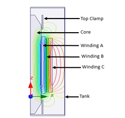 Figure 1: 2D geometry of the DSP plant transformer
2.1. Design based on the International Electrotechnical Commission (IEC) harmonic spectrum
The no-load losses and stray losses in windings and structural parts evaluated at nominal tap position are tabulated in Table 1. In order to compute these losses to account for the presence of harmonics it is necessary to obtain the values of the harmonic loss factors using the IEC 519-2014 [19] standard. Generally, from a manufactures perspective, the case of considering the harmonic spectrum proposed by this standard for a transformer intended to operate in a DSP plant is when there is no full harmonic spectrum supplied by the IPP. The harmonic spectrum recommended by IEC is shown in Figure 2.
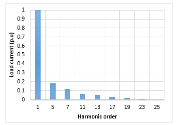 Figure 2: IEC 519-2014 Harmonic spectrum [2]
To estimate the service losses due to this harmonic spectrum, the transformer is initially designed at fundamental frequency to produce the rated losses as shown in Table 1. Thereafter, a harmonic loss factor is computed based on the supplied harmonic spectrum. The authors have presented a detailed computation of the harmonic loss factor in [17] and [18]. The Harmonic factor is in essence intended to predict the increase in the transformer losses under harmonics condition. The resultant service losses that will occur in transformer is as tabulated below.
Table 1: Tabulated loss computation under a harmonic spectrum
| Type of loss | Rated losses (W) | Harmonic factor | Service losses (W) |
| No-load | 0.180 | 1 | 0.180 |
| I2R | 11.041 | 1.055 | 11.654 |
| Winding Eddy | 0.213 | 3.986 | 0.921 |
| Other stray | 1.194 | 1.252 | 1.495 |
| Tank-HV side | 0.249 | 1.252 | 0.312 |
| Tank-LV side | 0.494 | 1.252 | 0.619 |
| Bus-Bar | 0.013 | 1.252 | 0.129 |
| Top yoke Clamp | 0.029 | 1.252 | 0.036 |
| Bottom yoke Clamp | 0.046 | 1.252 | 0.058 |
| Flitch plate | 0.02 | 1.252 | 0.003 |
From both the fundamental and harmonic losses above, it can be noticed that the loss percentage error is higher for winding stray losses. Additionally, the core losses are observed to be constant, indicating that the no-load losses are independent of the harmonic currents. The minimum winding stray losses as a result of axial and radial leakage fields are computed by optimizing the selection of conductor dimensions while maintaining the permissible flux and current density of the winding [20] and [21]. The transformer winding subject to harmonic distortion is designed using continuously transposed cable epoxy (CTCE) with minimum axial and radial dimensions of each conductor to reduce the eddy losses [20] and [21]. The tank is designed using mild steel which hold a nonlinear permeability. The quantity of the magnetic field in the tank walls is evaluated by eliminating the impact of nonlinearity. Thereafter, the losses in the LV and HV tank walls are computed taking into account the effect of nonlinearity through repetitive estimation. The flitch plates are also mild steel type and contain slots at the upper and lower positions. While their loss quantity is low compared to winding eddies and tank losses under harmonic effects, the magnetic field quantity is high which results in the flitch plate being more susceptible to HS temperature.
2.2. Design based on the harmonic studies
The harmonic current level at the PCC is presented in Figure 3. The results are obtained by modelling the DSP plant in DigSILENT Power Factory as a single line diagram which is composed of the DSP plant passive components. The highest harmonic current order corresponds with the measured harmonic data. Notably, this high harmonic order exceeds the recommended IEEE spectrum presented in the last section.
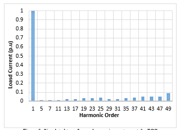 Figure 3: Simulated transformer harmonic spectrum at the PCC
The corresponding results when the design philosophy is tailored with the simulated harmonic spectrum are shown in Table 2. There are extreme differences in the percentage error between fundamental losses and the services losses. The transformer losses are observed to be even more extremely sensitive towards the simulated harmonic spectrum compared to the previous case. At large, these results outline the obligation for IPP’s to conduct harmonic studies in order to provide technical information to manufactures which reflect the actual harmonic distortions that will be realised by the transformer and to design transformers suitable for such extreme conditions.
Table 2: Transformer losses based on actual DSP plant harmonic spectrum
| Type of loss | Rated losses (W) | Harmonic factor | Service losses (W) |
| No-load | 0.180 | 1 | 0.180 |
| I2R | 11.041 | 1.055 | 11.654 |
| Winding Eddy | 0.213 | 3.986 | 0.921 |
| Other stray | 1.194 | 1.252 | 1.495 |
| Tank-HV side | 0.249 | 1.252 | 0.312 |
| Tank-LV side | 0.494 | 1.252 | 0.619 |
| Bus-Bar | 0.013 | 1.252 | 0.129 |
| Top yoke Clamp | 0.029 | 1.252 | 0.036 |
| Bottom yoke Clamp | 0.046 | 1.252 | 0.058 |
| Flitch plate | 0.02 | 1.252 | 0.003 |
To analyse the complete transformer harmonic response (THR), Figure 4 shows the results of the predicted transformer losses by IEC harmonic spectrum and compares them with the simulated harmonic spectrum the transformer is subjected to while in service. The transformer under inspection was designed without the provision of a full harmonic study from the IPP, and judging from the results, the indication is that it was under-designed for the environment it was intended to operate, which would explain the reported high temperature rise and oil gassing patterns. Subsequently, this knowledge gap led to insufficient design of the winding conductor sizes and cooling system for this application.
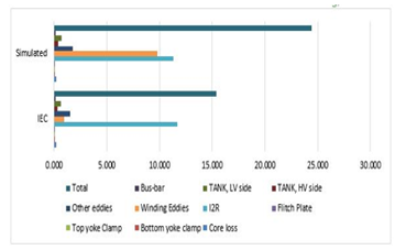 Figure 4: Loss comparison (IEC vs. Simulated Harmonic Spectrum)
In the next section, the temperature rise due to the increase in service losses is presented.
3. Thermal design
At tender stage, the transformer technical specifications supplied by IPP’s to the manufacture generally include information about the permissible top oil, mean winding and HS temperatures. Electrical designers are then challenged to optimize transformer designs such that they adhere to the IEC 60076-2 [22] and IEEE C57.91-1995 [23] standards and to design the thermal and cooling requirements at an ambient temperature. During the manufacturing stage, as part of the Factory Acceptance Tests (FAT’s) for newly manufactured transformers, the temperature rise test is conducted with the intent to demonstrate these temperatures, at full load and specified ambient temperature. The loading capability of the transformer is predominantly regulated by the HS temperature. In accordance with the IEC, the HS temperature is described as the mean winding temperature rise over the mean oil temperature multiply by a HS factor [22] and [23].
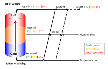 Figure 5: Simulated transformer harmonic spectrum at the PCC
A simplified thermal model of the transformer at fundamental frequency, IEC spectrum and simulated spectrum are shown in Figure 5. In this case, an IEC factor of 1.1 for DSP plant transformers is used in the calculation of the HS temperature. In Figure 5, the temperature rise within the windings is observed to increase linearly from the winding bottom to the top. A constant temperature difference between the oil duct and winding conductor along the winding is also observed. Moreover, the HS temperature is greater than the winding temperature rise as a result of the transformer losses.
The maximum error for the hot spot temperature between the fundamental values against the actual spectrum is 153%. That is 70% more than the HS temperature it was designed for under the IEC spectrum. This outcome clearly indicate that the transformer oil pumped through the winding conductors to execute the required cooling is not sufficient for transformer loading of actual harmonic spectrum. For the cooling system, the transformer oil viscosity and density vary with temperature rise, as such heat affects the fluid-flow sequence. Moreover, the quantity of the thermal fields resulting in such high HS temperature is derived from joule losses as a result of current flow in the windings and increased electromagnetic fields under harmonic conditions.
4. Stray gassing patterns
This section present findings of oil samples taken from the oil-filled hermetic DSP plant transformer under study for laboratory tests. The transformer was suspected to have oil gassing as indicated by the installed Oil Temperature Indicator (OTI). The results of Dissolved Gas Analysis (DGA) are given in Table 3. These results were taken after the transformer was in operation for about 4% of the predicted service life based on the design philosophy considering the IEC 519-2014 [19] to compute the losses, thermal and cooling requirements.
Table 3: DGA oil sample results (ppm)
| Type of gas | Limits | Gas concentration |
| H2 | <100 | 1478 |
| O2 | – | 28899 |
| N2 | – | 72484 |
| CO | <1000 | 28 |
| CO2 | <15 000 | 860 |
| CH4 | <80 | 438 |
| C2H4 | <150 | 36 |
| C2H6 | <35 | 561 |
| C2H2 | <7000 | 18 |
| TCG | <720 | 2541 |
The adverse effect for under-designing this transformer for requirements such as suitable conductor choice and size, and cooling system can be observed from the gas concentration exceeding the permissible IEC limits as shown in red in Table 3. Due to the excessive nature and production rates of hydrogen, a possible solution would be to replace the oil in all the affected units in case there were contaminants in the oil that resulted in the production of the abnormal gassing patterns. If the observed gassing patterns persist after the oil replacement, then a redesign of the transformer units might be needed. A proper harmonic study of the DSP plant as well as the loading conditions should be conducted in order to design for the DSP conditions. For the above case, the oil in the transformer was replaced to counter the abnormal gassing phenomena. As can be seen from Table 4, replacing the oil had a positive impact on the gases in that new DGA results showed that all of the gasses were within the specified limits. This then proved the suspected oil degeneration.
Table 4: DGA oil sample results after oil replacement (ppm)
| Gasses | Limits [23] | Gas concentration |
| H2 | <100 | 150 |
| O2 | – | 19455 |
| N2 | – | 90800 |
| CO | <1000 | 89 |
| CO2 | <15 000 | 2291 |
| CH4 | <80 | 84 |
| C2H4 | <150 | 0 |
| C2H6 | <35 | 222 |
| C2H2 | <7000 | 0 |
| TCG | <720 | 545 |
Air and moisture are generally the main determinants of gas pressure in the transformer oil. The progression of these components are determined by the transformer tank design and loading profile. The above irregular gas bubbling patterns are observed at hot spot temperature [22] far beyond the maximum permissible temperature of 78°C by the IEC. These patterns instigate rapid ageing of oil and cellulose insulation.
5. Findings and possible remedies for stray gassing
Novelty, remedial measures proposed on the current work from a transformer manufacture perspective in addressing stray gassing problems are summarised. These measures are based on collated data from many case studies conducted in the factory. During transformer service, these studies have been found to be linked up to the generation of hydrogen arising from stray gassing, in which stems from severely hydro-treated mineral oil, but is also strenuously affected by transformer thermal aging of polymers, choice of core steel grade, zinc tank walls and vanishes.
5.1. Harmonic spectrum
It was observed that an underestimation of the harmonic spectrum may affect the application of adequate winding design to account for the actual harmonics. Moreover, an improper cooling system is designed for the reduction of the HS temperatures in the windings and structural parts. In addressing these shortcoming, during the design stage, a complete harmonic spectrum of a DSP plant must be provided as it is critical for electrical designers in the computation of transformer load losses. The authors, recommends collaboration between the IPP and the manufactures to carry out in depth harmonic studies. The latter will enable adequate winding design and sufficient cooling system for the generated hotspot temperatures.
The main problems linked up to the tank walls include apertures, bubbling, orange peel and fissures. During the transformer manufacturing assembly line, these problems arises during processes linking up the tanking and painting phase.
5.2. Gummy tracks on the transformer tank walls: After drying out
Gummy tracks on the transformer tank walls arises from the addition of a sluggish drying dissolvent resulting to poor dissipation of the dissolvent and an insufficient hardening agent to the tank walls coating. The gaps among layers have been observed to be deficient when the coating is extremely dense and the coating layer is still wet. Additionally, the gummy tracks on the tank walls has been found to be due to contaminated tanks walls prior to coating.
5.3. Apertures in transformer tank walls
Apertures in tank walls during the assembly line may arise when the tank steel sheets are not cautiously handled. This phenomena has been observed as voids of diameter of about 0.1mm. Additionally, if the coating has not been settled for a certain period, the coating viscosity will be high and potentially the air bubbles have not been cleared. Additionally, prior to the tank welding, shot blasting must not be carried for the spare parts.
An adequate drying dissolvent and hardening agent must be designated and moderately added. The manufacture must also maintain the coated tank walls pollution-free. A best practice might be coating of the top-coat after the undercoating has completely dried out. When the climate is inimical during the assembly line, then the manufacture must ascertain excellent airing. The coating must not be carried out at high temperature and moisture.
6. Conclusion
This work, presents the results of stray gassing results that were carried out on a 2500kV, mineral-oil filled transformer. Particularly, solution oriented on the impact of harmonic currents on the service losses and thermal performance of the studied DSP the plant transformer. Moreover, the observed stray gassing occurrences of the unit as a result of (1) the generation of HS temperatures in the active part components; and (2) the core steel grade, zinc tank wall surface and coating.
In the case of an IPP who is not well informed about the actual harmonic levels occurring in the DSP plant, the authors recommend that manufactures make provision of the harmonic spectrum simulation prior to the electrical design process. In any case if the IEC harmonic spectrum meet the needs of the IPP, there should be a clear written agreement between the IPP and the manufacturer regarding the maximum permissible harmonics being in accordance with the IEC spectrum.
Novelty, findings of this work indicate that the generation of hydrogen arising from stray gassing may stem from severely hydro-treated mineral oil, but is also strenuously affected by transformer thermal aging of polymers, choice of core steel material and tank walls vanishes. The production surplus of methane and ethane are also witnessed in the first years of service and reaches substantial concentration levels. Potentially, these occurrences also arises from the thermal aging of polymers. The authors make some recommendations to utility owners to make a distinction of stray gassing from transformer fault by means of routine inspection aside from DGA value basis withal to the increase in gas diffusion rate. Finally, the authors highlight the need to establish standards that will provide support for transformers intended to operate in DSP applications. At large this work identifies the shortcomings of the design considerations for transformers intended to operate in DSP applications and recommend corrective measures to address these challenges.
The authors make a significant contribution by further recommending procedures that can be employed as remedies during the design phase and manufacturing processes.
Conflict of Interest
The authors declare no conflict of interest.
- Government Gazette,” Integrated Energy Plan (IEP)”, The National Energy Regulator Act, 34, 2008, doi: wp-content/uploads/2017/04/IEP-IRP-gW-ELA-Comment-310317.pdf.
- B. A Thango, D.B Nyandeni, P.M Molepo, “Solar Power Plant Transformer Loss Computation under Harmonic Currents using Finite Element Method”, in 9th CIGRE Southern Africa Regional Conference, 1 – 4, 2019.
- E. Arslan, S. Sakar, M. E. Balci,” On the no-load loss of power transformers under voltages with sub-harmonics”, in IEEE International Energy Conference (ENERGYCON), 228-233, 2014, doi: doi: 10.1109/ENERGYCON.2014.6850433.
- S.V. Kulkarni, S.A. Khaparde,” Stray loss evaluation in power transformers-a review”, IEEE Power Engineering Society Winter Meeting. Conference Proceedings, 3, 2269-2274, 2000, doi: 10.1109/PESW.2000.847708.
- T. D. Kefalas and A. G. Kladas, “Harmonic Impact on Distribution Transformer No-Load Loss,” in IEEE Transactions on Industrial Electronics, 57 (1), 193-200, 2010, doi: 10.1109/TIE.2009.2030207.
- E. So, R. Arseneau and E. Hanique, “No-load loss measurements of power transformers under distorted supply voltage waveform conditions,” in IEEE Transactions on Instrumentation and Measurement, 52(2), 429-432, 2003, doi: 10.1109/TIM.2003.809910.
- B.A. Thango, J. A. Jordaan and A.F. Nnachi, “Service Life Estimation of Photovoltaic Plant Transformers under Non-Linear Loads”, 2020 IEEE PES/IAS PowerAfrica Conference, 1-5, 2020 doi: doi: 10.1109/PowerAfrica49420.2020.9219912.
- A. Elmoudi, M. Lehtonen and H. Nordman, “Effect of harmonics on transformers loss of life,” Conference Record of the 2006 IEEE International Symposium on Electrical Insulation, Toronto, Ont., 408-411, 2006, doi: 10.1109/ELINSL.2006.1665344.
- K. Dursun and N. Rahmanov, “Harmonic load losses in power transformer windings using Finite Element methods,” Eurocon 2013, 1526-1530, 2013, doi: 10.1109/EUROCON.2013.6625180.
- D. M. Said and K. M. Nor, “Effects of harmonics on distribution transformers,” in 2008 Australasian Universities Power Engineering Conference, 1-5, 2008.
- J. Weesmaa, M. Sterner, B. Pahlavanpour, L. Bergeld, J. Nunes and K. Sundkvist, “Study of stray gassing measurements by different methods,” 2013 Annual Report Conference on Electrical Insulation and Dielectric Phenomena, Shenzhen, 184-189, 2013, doi: 10.1109/CEIDP.2013.6748192.
- I. Hohlein, “Unusual cases of gassing in transformers in service,” in IEEE Electrical Insulation Magazine, 22 (1), 24-27, 2006, doi: 10.1109/MEI.2006.1618968.
- D. Martin, N. Lelekakis, J. Wijaya, M. Duval and T. Saha, “Investigations Into the Stray Gassing of Oils in the Fault Diagnosis of Transformers,” in IEEE Transactions on Power Delivery, 29 (5), 2369-2374, 2014, doi: 10.1109/TPWRD.2014.2316501.
- F. Jakob, P. Noble and J. J. Dukarm, “A Thermodynamic Approach to Evaluation of the Severity of Transformer Faults,” in IEEE Transactions on Power Delivery, 27 (2), 554-559, 2012, doi: 10.1109/TPWRD.2011.2175950.
- M. Phoshoko, “Predictive maintenance of transformers through stray gassing studies”, 66th AMEU Convention, 2017, doi: wp-content/uploads/2017/11/Pages-from-AMEU-2017_-46-51.pdf.
- B. A. Thango, J. A. Jordaan and A. F. Nnachi, “Stray Gassing of Transformer Oil in Distributed Solar Photovoltaic (DSPV) Systems,” 2020 6th IEEE International Energy Conference (ENERGYCon), Gammarth, Tunis, Tunisia, 484-488, 2020,doi: 10.1109/ENERGYCon48941.2020.9236522.
- B.A. Thango, J. A. Jordaan, A.F. Nnachi, “Effects of Current Harmonics on Maximum Loading Capability for Solar Power Plant Transformers”, 2020 International SAUPEC/RobMech/PRASA Conference, 1-5, 2020, doi: 10.1109/SAUPEC/RobMech/PRASA48453.2020.9041101.
- B.A. Thango, J.A. Jordaan, A.F. Nnachi, “Step-Up Transformers for PV Plants: Load Loss Estimation under Harmonic Conditions”, 19th International Conference on Harmonics and Quality of Power (ICHQP), 1-5, 2020, doi: 10.1109/ICHQP46026.2020.9177938.
- IEEE 519: 2014, “Recommended practices and requirements for harmonic control in electrical power systems”, 1-29, 2014, doi: 10.1109/IEEESTD.2014.6826459.
- T.V. Oommen, S.R Lindgren,” Bubble evolution from transformer overload”, IEEE/PES Transmission and Distribution Conference and Exposition. Developing New Perspectives (Cat. No.01CH37294), 1, 137-142, 2001, doi: 10.1109/TDC.2001.971223.
- M.C. Hlatshwayo, The computation of winding eddy losses in power transformers using analytical and numerical methods, Masters Thsis, 2013.
- IEC 60076-7, “Power transformers – Part 7: Loading guide for mineral-oil-immersed power transformers”, 2005.
- “IEEE Guide for Loading Mineral-Oil-Immersed Transformers,” in IEEE Std C57.91-1995 , 1-112, 1995, doi: 10.1109/IEEESTD.1995.8684643.