Use of Unmanned Aerial Vehicles in Aircraft Inspection
 , Martin Bugaj 1, Alena Novák Sedláčková 1, Branislav Kandera 1, Anna Stelmach 2, Tomasz Lusiak 3
Adv. Sci. Technol. Eng. Syst. J. 6(3), 182–188 (2021);
 DOI: 10.25046/aj060321
The article further extends the researched issue of the unmanned aircraft use in the pre-flight and post-flight visual check of aircraft. Procedures of pre-flight inspection are fulfilled by the aircraft maintenance certified staff or the crew member before flight. The process is similar for all categories of aircraft, but its implementation differs for individual specific types of aircraft. Therefore, the article will deal only with small training aircraft, which will be used to verify the use of UAV (Unmanned Aerial Vehicle) in normal operation. It identifies and defines the problem of using multiple UAV in swarms and their usage in standard activities in aircraft operation. The outcome should be a reduction of the number of possible failures cause by the human factor with impact on the safety in operations. Proportionately important fact is the desirable minimization in the time necessary to carry out a pre-flight inspection process, which will improve the final indicator of the efficiency in aeroplane operations.
1. Introduction
This article builds on the existing field of research by the authors on the use of UAV by maintenance and training organizations as well as commercial airlines. In this research field, the articles Use of Unmanned Aerial Vehicles in Aircraft Maintenance [1] and Unmanned Aerial Vehicles and Their Use for Aircraft Inspection [2] have been published. In aviation, defined legal regulations and standards are implemented and must be strictly applied. Procedures related to aircraft periodic inspections and checks are performed during aircraft operations by certified organizations, always supervised by the Continuing Airworthiness Management Organization (CAMO). According to Commission Regulation (EU) no. 965/2012 laying down technical requirements and administrative procedures related to air operations pursuant to Regulation of the European Parliament and Council Regulation (EC) No. 216/2008 are aircraft operators at the same time also holders of an Air Operator Certificate (AOC). Aviation companies are obliged to implement a management system in operation with working management of safety risks in whole process of operation (Safety Management System – SMS). On top of that airlines are prior to each flight expected to perform own routine pre-flight inspections. An urge to utilize new technologies and equipment that reflect changing nature of industry was a result of these rapid changes. Similarly, as industry puts an emphasis on the new technologies in accordance with Industry 4.0 principles, so must certified maintenance organizations (MROs) and continuing airworthiness management organizations (CAMOs) follow suit and utilize “Smart Technologies” [3] The collective response of maintenance and aviation industry organisations led to the creation of the concept “Smart Hangar”, which enables CAMOs and MROs to conduct their business with a higher degree of objective accountability in detecting human error.
The UAV operation worldwide is growing in numbers, as are the areas of human activity in which UAV are operated professionally. They are part of all areas of human life and are already an integral part of the equipment of law enforcements and rescue units, photogrammetry, transport, construction, industry, research, logistics, they can furthermore be used for youngsters to play with. [4]. Technology evolves and changes with their increasing use. At the same time a relevant legislation for a safe utilisation should be in line with technological progress. This field must be protected by European legislation and national in a manner that will not restrict freedom [5].
Recently Intel and Airbus have started a cooperation in a bid to further improve this process. Intel delivers UAV equipped with video recording devices that enable recording images or data which can later be used to generate whole three-dimensional models of Airbus aircraft. Airbus Aerial a subsidiary established by Airbus S.A.S provides equipment inspection services in different aviation industry sectors [6]. There are also other similar companies that operate in this market, such as French Ubisense S.A.S, MRO Drone Ltd from Great Britain and Canard Drones from Spain. These have lately developed particular procedures to provide inspection solutions for airports as well as aeroplanes [7], [8].
The goal of our project is to demonstrate the possible use of UAV system for aircraft inspection by a small aviation organization.
2. Definition of Smart Hangar concept
Smart Hangar can be defined as a set of actions including digitization of analytical tools, automation of its environment, smart manufacturing and logistics. If we should specify the concept of “Smart Hangar” in detail, it is necessary for the maintenance organization to expand key areas as they are listed in Figure 1.
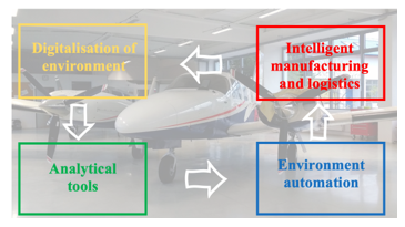 Figure 1: Concept of Smart Hangar for MRO. (Source: authors)
2.1. Digitization of environment and virtualization of tasks
In order to establish a functioning “Smart MRO” all work procedures and management systems that are effective at the moment need to be digitized to form a basic framework of the system. Maintenance organization, a continuing airworthiness management organization, hangar or even an airport that utilizes the electronic (paperless) system are able to achieve higher efficiency of operation. This can be done by online monitoring, assignment and approval of maintenance tasks. An MROs maintenance technician has access to the corporate network, therefore is able to work anytime from any location. Electronic handheld devices enable him to track, compare and record maintenance task [9].
2.2. Analytical tools of intelligent hangar
Digitization enables meaningful data analysis and improvement of internal processes. It also helps airlines optimize activities in cost planning, warehouse management and materials logistics. Employees can foresee errors in aircraft repair and maintenance and better plan their resources (both material and human). This is possible through the advanced analysis that results from data collection. The use of interactive prediction software bots not only enables better control of material logistics and supplies, it also helps to reduce costs in MROs and the amount of supplies [10].
2.3. Robotization and automation of an environment
Introduction of collaborative robots brought increased productivity, work performance efficiency and directly increased work procedures and processes. Utilization of digitized end-to-end workflow monitoring resulted in higher level of safety and quality. After establishment of such innovative work environment unmanned aerial vehicles will be able to perform aircraft visual inspections prior, during or after the maintenance tasks are carried out. Further implementation of Automated Guided Vehicles (AGV) as well as Intelligent cabinet will help in search for and point-to-point transport of tools and aircraft parts from the storage to the place of the maintenance (point-to-use) in real time [9].
2.4. Intelligent manufacturing and logistics
3D printing, free-form fabrication or rapid prototyping are terms used to describe process of additive manufacturing (AM). It describes a process of merging materials in order to create any object/product from 3D model data. Manufacturing aircraft components using additive manufacturing method of 3D Printing (3DP) is eco-friendly and presents an opportunity to optimize the design of components at fraction of costs. Adaptive manufacturing provides range of advantages compared to regular manufacturing. Waiting time when replacing specific low-volume components that need to be replaced as soon as possible can be significantly reduced. It also uses less resources compared to standard manufacturing process. On the other hand, significant engineering and certification experience is required to fully utilize such technology to meet exact requirements of national aviation authorities (or EASA) in order for new parts to be approved for installation.
3. Research on pre-flight inspection process using UAV at University of Žilina (UNIZA)
Organisation and performance of aircraft maintenance at the University of Žilina conforms to the legislation of European Union. UNIZA is an Approved Maintenance Organization (AMO) with the appropriate permits and licence that conform to the requirements of Commission Regulation (EU) No. 1321/2014 under number SK.MF06. It sets out requirements for aircraft (EASA aircraft) that meet the requirements set out in Article 2 (1) of Regulation (EU) No.182/2011 of the European Parliament and of the Council No.1139/2018. Maintenance organizations have to meet the following requirements:
- for complex engine-powered aircraft and aircraft used by air carriers licensed in accordance with Regulation (EC) No 1008/2008 and their components (Part 145).
- for aircraft other than complex engine-powered airplanes and their components (Part-M Subpart F or Part-CAO).
Aircraft at University of Žilina are maintained in line with the certification and according to the latest regulations. Only trained and certified personnel with corresponding technician’s licence is authorized to release aircraft into the service.
Pre-flight aircraft inspection is always performed in line with the approved aircraft manual as well as the organization’s operations manual.
3.1. Pre-flight inspection
PAA34-220T* SENECA* V* is a modern twin-engine aircraft used by University of Žilina for pilot trainings as well as aerial work. We have selected this aircraft for the research purposes. Inspection instructions listed in the following paragraph are extracted from the flight manual of the aircraft. In addition, procedures that are unique for the aircraft type have been also considered. First, it is required to inspect the general state of aircraft. It has to be inspected from outside as well as from inside. In case of winter weather conditions any build-up of snow or even icing on the flight and control surfaces has to be removed. Functionality of all lights and flashlight has to be ensured prior to the planned night flight. Operational manual section of Airplane Flight Manual offers in-depth clarification of information regarding the pre-flight inspection procedures [12]. Inspection process of PA34-220T SENECA* V aircraft must be done in order depicted in figure 2. Aircraft cabin is first on the pre-flight inspection checklist (Figure 2, Point 1). According to the flight manual, correct operation of individual lightning, power supply, navigation and communication elements has to be ensured. In addition, all mechanical and safety elements together with correct fixation of luggage and flight documentation have to be inspected as well.
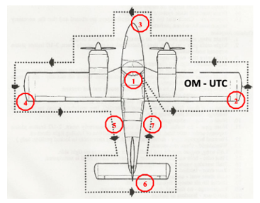 Figure 2: Inspection sequence of PA34-220T Seneca V aircraft. (Source: authors)
After this is completed an exterior inspection follows. Aircraft inspection starts with the check of the starboard wing following with a right engine in a counter clockwise direction. During this inspection every mechanical wing part such as flaps and ailerons are checked. Among other elements that are inspected are engine, propeller, amount of fuel, removal of fuel sludge as well as fuselage elements and chassis of the aircraft; at the front (Figure 2, point 3) we inspect windshield, tires, front landing gear leg, cargo compartment in the nose of aircraft together with landing reflector. While inspecting the top port wing (Figure 2 point 4), every mechanical wing parts such as flaps and ailerons and flaps are checked together with an engine, propeller, fuel quantity, fuel sludge removal, icing indication, pitot tube, chassis control and fuselage parts. Inspection then continues with the fuselage on the left side (Figure 2, point 5). This segment consists of checks of fuselage for the presence of snow and ice, antenna, cargo bay, pitot-static system and side door. Similarly, the rear part of the aircraft is inspected for the presence of any snow or ice residues. It is followed by an inspection of elevator, rudders, air intake system. Moving to the right (Figure 2, point 7) it is required to check the fuselage for the presence of snow and ice. As on the left side of aircraft antennas and pitot-static system must be checked for any debris or dirt that may hamper their operation.
4. Use of UAV in pre-flight inspection
When inspecting an aircraft using a UAV this has to be performed outside. Movement and equipment of the UAV has to meet certain requirements when operating in the Control Zone (CTR) of particular airport. These include propeller cover, outdoor movement sensors and navigation including GNSS navigation. The decisive factor for the use of UAV in an aircraft monitoring and control system is the software and subsequent applications for data evaluation.
4.1. Methodology for aircraft object identification and changes
When performing pre-flight inspection, it is important to correctly recognize and identify the individual components and significant parts of the fuselage, engine and propeller blades to be inspected. Correct identification of individual components is a very important task. The recognition of any objects in general can be expressed by the following sequence of steps:
- “Image acquisition”;
- “Pre-processing”;
- “Segmentation”;
- “Representation”;
- “Classification”.
After obtaining an image from a source (captured by a camera or from video), it is pre-processed, which means the image is prepared into such a form that it is possible to implement algorithms for further processing. This step can include converting a colour image into an image in shades of grey (see Figure 3), or using filters to remove, or suppress noise. Image processing algorithms are deployed in this step. The next step is segmentation, which extracts objects of interest, thus separating the foreground (what interests us) from the background (everything else). In the picture, the objects of interest are rivets on wings, but undesired objects (noise) also got there.
This is a general model, which means that not all blocks may always be followed. Their order may be changed, or the steps may be completely replaced by other procedures or combined into separate blocks. Formally, we can model the image as a continuous (image) function of two variables f(x,y), where f represents the value of brightness and (x,y) represent the coordinates on the surface. In the case of a dynamic image (video), we can also express the image as a function of three variables f(x,y,t), where t means time.
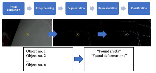 Figure 3: General procedure of object recognition on the example of rivet and deformation recognition. (Source: authors)
“Smart Hangar” solutions depend on partial systems and applications that safeguard the functioning of the whole system. “Model – driven Software Development” (MDSD) (see Figure 4) based on an automatic code generation of system requirements specification, it is typically used to providing specific properties to the whole system [13]. The module “DeRoS” safety specification “DSL” provides a simple and declarative syntax that makes the task of implementing the safety-related requirements accessible to robotics experts with less software engineering expertise. The risk of errors is reduced because the Declarative Robot Safety (DeRoS) declaration controls the automatic generation of all safety-related code. Our model approach directly enables implementation-independent reuse of the safety-relevant part of a robot controller between different versions, since the DeRoS declaration does not need to be changed when the underlying software changes (with the exception that names shared between DeRoS rules and component interfaces must be kept consistent) [14]. Such an approach can be utilized when enforcing safety regulations for unmanned systems or to state and improve system cross-sectional properties, as power unit energy balance, safety and timing or to supervise and organize the behaviour of number of UAV in a fleet system such as UAV swarm when inspecting more than one aircraft for example [15].
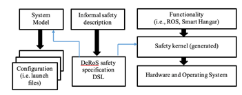 Figure 4: UAV Software platform for MDSD. (Source: authors)
4.2. Design of a model for performing an inspection
PA34-220T Seneca V aircraft pre-flight inspection process has been detailed in chapter 3.1 of this article. If we are to carry out an aircraft pre-flight inspection, input variables and environmental properties, the core elements of the aircraft sensing model that identifies the state of the aircraft, need to be defined first. Next, the UAV flight and scanning trajectory, the time intervals of UAV movement relative to the defined trajectory, and the incremental termination of the scanning process must be defined and established. [16]. In the 3D-space of the proposed model, UAV will be characterised by a material point. We need to establish the start (and end) point of UAV take-off, then the altitude for individual reference points within specified trajectory, the total estimated period of its entire pre-flight inspection in the aircraft scanning phase [17, 18]. However, this describes the initial part of a complete aircraft pre-flight inspection. As soon as possible after the UAV inspection data are captured, they need to be processed and evaluated. Result of this operation should be a comprehensive information regarding the state of the aircraft which is then sent to the pilot. After inspecting the information, pilot decides whether an in-depth personal inspection of the aircraft or its parts that that deviate from the UAV sensing model is required. The pattern furthermore explains certain tasks included in the aircraft pre-flight examination, (see Figure 5) which must be carried out physically in accordance with the prescribed pre-flight inspections in the relevant aircraft documentation.
In order to create a functional model, it has to contain an information about the beginning point of UAV pre-flight inspection procedure. In the essence it surely is an exactly defined point at which the UAV take-off as well as the landing takes place. Such point is created during the planning of flight trajectory model by defining the default position. The flight route must respect the procedure of in-person pre-flight inspection carried out by a pilot as shown on the Figure 2. Model of pre-flight inspection can be seen on the Figure 6.
During the creation process of this functional model, based on the defined field of partial position points X1 to Xn; Y1 to Yn; Z1 to Zn. The initial take-off position of UAV is defined as:
X1 = 0; Y1 = 0; Z1 =0 (1)
The UAV initial position at its start should be identical to its final position after its flight performance. In order to model the entire trajectory (see Figure 6), a sequence of position points must be defined. To ensure the safety of the scanning process and to obtain relevant data, a requirement for the constant altitude of the
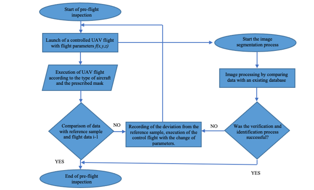 Figure 5: Aircraft inspection flowchart with image classification and evaluation (Source: authors)
UAV during the execution of the aircraft inspection was formulated. The determination of the constant altitude is based on several assumptions, namely:
- dimensions of the aircraft in the z-axis,
- sufficient resolution value of the scanning device,
- security aspect,
- type of information obtained from the UAV.
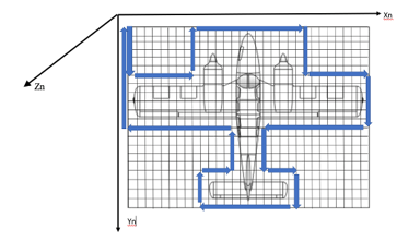 Figure 6: Model of UAV trajectory. (Source: authors)
In order to prevent potentially dangerous contacts with an aircraft it is of a paramount importance to design a so-called restricted no-go zone for UAV. Otherwise, the damage an aircraft may sustain can translate to considerable operational and financial consequences as a Figure 7. The minimum distance from any part of the aircraft has been set at:
![]() This value guarantees a sufficient safe distance from the aircraft even in the event of failures in the operation of the UAV during the pre-flight inspection, as shown in Figure 7. It is based on the assumption that no part of the aircraft exceeds the edge of the aircraft by more than 0.5 m (e.g., rod antenna).
This value guarantees a sufficient safe distance from the aircraft even in the event of failures in the operation of the UAV during the pre-flight inspection, as shown in Figure 7. It is based on the assumption that no part of the aircraft exceeds the edge of the aircraft by more than 0.5 m (e.g., rod antenna).
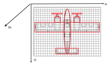 Figure 7: Restricted no-go zones for UAV. (Source: authors)
After the default starting position is defined, other reference points, meaning points where the flight trajectory has to be altered, are programmed. Each point is determined by its position:
B1 (“X1,Y1,Z1”); B2 (“X2,Y2,Z2”); ……. Bn (Xn,Yn,Yn) (3)
Considering that the flight altitude from Z1 to Zn will be constant, the partial trajectories D (distances) between all points can be determined as follows:
![]() Where Xi and Yi determine the i-th point B, Xj and Yj coordinates present position of j-th point B of the set path of movement. The final trajectory is specified by reference coordinates and distances between determined UAV positions. The trajectory must be defined by data describing proposed restricted area around the aircraft. Suggested UAV flight trajectory model stands as:
Where Xi and Yi determine the i-th point B, Xj and Yj coordinates present position of j-th point B of the set path of movement. The final trajectory is specified by reference coordinates and distances between determined UAV positions. The trajectory must be defined by data describing proposed restricted area around the aircraft. Suggested UAV flight trajectory model stands as:
![]() The B points are belonging to red zone (RZ) is described by points with coordinates “Pi” and “Pj” in such form. Model which defines the final UAV trajectory around aircraft is relevant and in such form also applicable in the phase of programming the UAV. Significance of this step lays in the mitigation of the damage that may be caused by a possible clash between the inspected aircraft and the UAV. Data gathered by the UAV during the pre-flight inspection must be processed. The processing takes place in the form of a comparison of the obtained data with an aircraft reference model. The reference model must meet all requirements placed on real flight aircraft condition before each flight inspection begins.
The B points are belonging to red zone (RZ) is described by points with coordinates “Pi” and “Pj” in such form. Model which defines the final UAV trajectory around aircraft is relevant and in such form also applicable in the phase of programming the UAV. Significance of this step lays in the mitigation of the damage that may be caused by a possible clash between the inspected aircraft and the UAV. Data gathered by the UAV during the pre-flight inspection must be processed. The processing takes place in the form of a comparison of the obtained data with an aircraft reference model. The reference model must meet all requirements placed on real flight aircraft condition before each flight inspection begins.
4.3. Discussion
The use of UAV during pre-flight inspection brings benefits in several areas. By eliminating the influence of the human factor, which can reduce the level of safety of the aircraft, it is possible to achieve an increase in safety. The use UAV pre-flight inspection tour around the aircraft following the manufacturer’s checklist. It’s necessary pay special attention to lose or “smoking” rivets (which have a residue around them), the safety of all bolts and nuts, and safety-wired devices. At the same time, it is possible to increase efficiency by introducing automation. UAV application could support both aviation and airport operations, it would decrease the maintenance costs and aircraft inspection procedures. [19]. Like other technologies, UAV bring a wide range of benefits. But besides the benefits, the sad truth about UAV is that there are certain burning flaws like sudden crashes, risks from hacking, and security and privacy issues that plague this part of the technology. [20]
Another aspect of the UAV pre-flight inspection system is the development of a UAV communication system with a hardware-software platform, which will be designed to automate the processes of processing and transfer of information between involved parties so that there are no security risks associated with the transfer and processing of acquired information. Although the use of UAV in any process in air transport is a very complex and lengthy process, its potential benefits are undoubtedly clear.
5. Conclusion
Significant technological developments in the field of UAV have recently caused conditions to be created for their use in specific areas of civil aviation. There are ever more use cases in this area for use of UAV, despite being perceived as a threat to civil aviation. The philosophy of Smart Airport consists of several advanced concepts, one of which is the use of UAV in the process of pre-flight inspections, this was also the subject of the presented article. Firstly, it was crucial to analyse and define technical and operational conditions for the UAV use in pre-flight inspection by detailed analysis of the environment, determining the nature of information that will form a set of input and output information and data and then creating a system to process and evaluate the data. The initial idea of creating this model of UAV application during a pre-flight inspection was to evaluate the overall aircraft condition. Potential threats were also described and a way of solving them was proposed. In the end, advantages of UAV application in the process of pre-flight inspections have been mentioned. Among the most important are the reduction of human factor influence in the performed pre-flight inspection, the time reduction allocated for this activity, which achieves a higher efficiency of the whole process. Further research actions would lead to a detailed definition of aircraft model reference samples for the purpose of obtained records comparison with the reference model. Furthermore, it will be required to develop a swarm model for UAV devices where several devices with diverse types of equipment (mechanical arm, laser scanner, digital camera, etc.) would cooperate with each other. Thanks to the use of modern digital and transmission technologies, it is possible to ensure real-time data comparison. However, it is always necessary to ensure the maximum level of safety of these processes when using UAV during the pre-flight inspection
Upcoming efforts will extend the experimental assessments to UAV simulations and actual flight tests to use probability numbers instead of frequencies which have been used in this case for demonstration purposes. In the author´s opinion and experience it is rather difficult to accomplish the certification and validation processes of safety functions as well as more efficient outcomes. For that reason, our strategy is to verify and validate already functioning safety system to guarantee that the safety system meets functional requirements and is suitable for risk mitigation. Besides, we will investigate how the UAV swarm can be implemented to monitor and ensure a safe flight operation of pre-flight inspection during this specific mission for example in aerodrome apron.
Acknowledgements
This publication was realized with support of Operational Program Integrated Infrastructure 2014 – 2020 of the project: “Intelligent operating and processing systems for UAV, code ITMS 313011V422”, co-financed by the European Regional Development Fund”.
- A. Novák, A. Novák Sedlackova, M. Bugaj, B. Kandera, T. Lusiak, “Use of Unmanned Aerial Vehicles in Aircraft Maintenance”, Transportation Research Procedia, 51, 160-170, 2020, DOI 10.1016/j.trpro.2020.11.018
- M. Bugaj, A. Novák, A. Stelmach, T. Lusiak, “Unmanned Aerial Vehicles and Their Use for Aircraft Inspection,” 2020 New Trends in Civil Aviation (NTCA), Prague, 45-50, 2020. doi: 10.23919/NTCA50409.2020.9290929
- J. Holl, “Hangar of the future Excelling in MRO”, 6. December 2016, Airbus S.A.S Source: https://www.airbus.com/newsroom/news/en/2016/ 12/Hangar-of-the-future.html
- P. Kurdel, A.N. Sedláčková, J, Labun, “UAV flight safety close to the mountain massif”,Transportation Research Procedia, 43, 319-327 2019. doi:10.1016/j.trpro.2019.12.047
- A.N. Sedláčková, P. Kurdel, B. Mrekaj, “Synthesis criterion of ergatic base complex with focus on its reliability”, INFORMATICS 2017 – Proceedings, 318-321, 2018. doi:10.1109/INFORMATICS.2017.8327267
- M. Fendt, “Airbus launches advanced indoor inspection drone to reduce aircraft inspection times and enhance report quality, Commercial Aircraft”, Airbus S.A.S , 2018. (Accessed: 10 April 2021)
- A. Ward, “Ubisense and MRO Drone launch world’s first ‘Smart Hangar’ solution”, Ubisense 18.April 2018 Source: https://ubisense.com/ubisense-and-mro-drone-launch-worlds-first-smart-hangar-solution/
- V. Ažaltovič, I. Škvareková, P. Pecho, B. Kandera, “Calculation of the ground casualty risk during aerial work of unmanned aerial vehicles in the urban environment”, Transportation Research Procedia, 44, 271-275, 2020. doi:10.1016/j.trpro.2020.02.043
- A.N. Sedláčková, P. Kurdel, J. Labun, “Simulation of unmanned aircraft vehicle flight precision”, Transportation Research Procedia, 44, 313-320, 2020. doi:10.1016/j.trpro.2020.02.037
- ST Engenniering: Smart MRO, internet 1.7.2020 https://www.stengg.com/en/aerospace/capabilities/smart-mro/
- Uniting Aviation, “The future of MRO: Emerging Technologies in Aircraft Maintenance”, Uniting Aviation on August 1, 2019. (Source: https://www.unitingaviation.com/amp/news/capacity-efficiency/the-future-of-mro-emerging-technologies-in-aircraft-maintenance/ ) (Accessed: 2 April 2021).
- Piper AIRCRAFT, “Airplane Maintenance Manual, Card 1 of 5, PA34-220T, SENECA III (ALL) and SENECA V (S/N’s 3448038 THRU 3448079), Piper Aircraft Corporation, 2017, April 17, 2007.
- M. Catlos, P. Kurdel, A.N. Sedlakova, J. Labun, M. Ceskovic, “Continual monitoring of precision of aerial transport objects”, Paper presented at the NTAD 2018 – 13th International Scientific Conference – New Trends in Aviation Development, Proceedings, 76-81, 2018. doi:10.1109/NTAD.2018.8551683
- A. Sorin, J. Kjeld, U.Schultz, “Towards Rule-Based Dynamic Safety Monitoring for Mobile Robots”, Journal of Software Egnieering for Robotics, 2016. DOI: 10.6092/JOSER_2016_07_01_P120
- F. Škultéty, B. Badánik, M. Bartoš, B. Kandera, “Design of controllable unmanned rescue parachute wing”, Transportation Research Procedia, 35, 220-229, 2018. doi:10.1016/j.trpro.2018.12.026
- Min Xue “UAV Trajectory Modeling Using Neural Networks”, 17th AIAA Aviation Technology, Integration, and Operations Conference. AIAA 2017-3072, 2017. doi: 10.2514/6.2017-3072
- H. Zhou, H.L. Xiong, Y. Liu, N.D. Tan, L. Chen, “Trajectory Planning Algorithm of UAV Based on System Positioning Accuracy Constraints. Electronics 9, 245-250, 2020. https://doi.org/10.3390/electronics9020250
- L. Tan, J. Wu,X. Yang, S. Song, “Research on Optimal Landing Trajectory Planning Method between an UAV and a Moving Vessel”, Appl. Sci. 2019, 9, 3708, 2019. https://doi.org/10.3390/app9183708
- F. Marcellin, “Positive uses of drones in aviation: UAV changing airports for the better”, Available at: https://www.airport-technology.com/features/positive-uses-of-drones-in-aviation/ (Accessed: 4 April 2021).
- A. Allouch, A. Koubâa, M. Khalgui, T. Abbes, “Qualitative and Quantitative Risk Analysis and Safety Assessment of Unmanned Aerial Vehicles Missions Over the Internet”, IEEE Access, 7, 53392-53410, 2019. doi: 10.1109/ACCESS.2019.2911980.