Microstrip Patch Antenna Designs with Quarter-Circular and Semi-Circular Slots in Patches for Wireless Communication Applications in Frequency Range of 1.2 GHz-4.6 GHz

Adv. Sci. Technol. Eng. Syst. J. 6(3), 257–262 (2021);
 DOI: 10.25046/aj060328
In this study, 6 unique microstrip patch antennas with quarter-circular and semi-circular slots in patches are proposed. It is aimed to investigate the effect of these slots in the designed topologies. The antennas operate for wireless applications including Personal Communication Service (PCS), 3rd Generation (3G), The Standard for Wireless Fidelity (WiFi)/Wireless Local Area Network (WLAN)/Bluetooth, Long Term Evolution (LTE) and Global System for Mobile Communications at 1.8 GHz (GSM-1800). Simulation results for antenna performance parameters such as fractional bandwidth, gain, radiation pattern, radiation efficiency and total efficiency are presented.
1. Introduction
This paper is an extension of work originally presented at 11th International Conference of Electrical and Electronics Engineering [1]. Multi-band feature is often required in wireless communication systems because simultaneous operation of multiple technologies could be desirable. One antenna type that satisfies that feature is microstrip patch antennas. Microstrip patch antennas have been preferred in many wireless communication systems. [2, 3]. Operation in multiple frequency bands can be obtained by placing slots in patches and/or ground planes [4–6]. Various studies report on slotted microstrip patch antenna geometries: In one report [7], a microstrip patch antenna with a slotted rectangular radiating patch and a defected ground plane suitable for Bluetooth, LTE, Universal Mobile Telecommunications System Band II (UMTS-II), Industrial, Scientific and Medical band (ISM), WLAN, Worldwide Interoperability for Microwave Access (WiMAX), RFID, Wireless Broadband (WiBro) and WiFi is examined. In [8], the authors examine a microstrip patch antenna with an air-filled substrate and 3 open slots. The antenna operates between 1.77 GHz – 2.65 GHz. In [9], the authors focus on a dual-band microstrip patch antenna that consist of two layers separated by an air gap, and a triangular ground slot. The structure operates at 1.8 GHz and 2.4 GHz.
In this article, 6 microstrip patch antennas with quarter-circular and semi-circular slots in patches aimed for wireless operations are proposed. Geometry of the antennas are unique. It is intended to investigate the effect of patch truncations in these antenna topologies. The truncations are located symmetrically on the patches. Antenna performance parameters are simulated. Simulations as well as optimizations are carried out by utilizing ANSYS HFSS.
2. Antennas
2.1. Antenna 1
Antenna 1 has 2 identical quarter-circular slots in patch. These slots are located two diagonal patch corners. Radius of quarter-circles is given by r1 (1.50 mm). The antenna is in square shape as all antennas in this article. Its operation range is 1.3905 GHz – 4.5739 GHz with a fractional bandwidth (FB) of 106.74%. Note that a simulation of the slotless configuration yields a resonance at 2.05 GHz using a coaxial probe as a feed located at (7, 9) mm. The frequency operation range is 1.365 GHz – 2.410 GHz with a fractional bandwidth of 55.36%. Operation frequency range is based on -10 dB impedance bandwidth (|S11|<-10 dB). Height of the substrate is 4.30 mm. Its relative permittivity value is 15.5, and loss tangent value is 0.0001. Same substrate material and substrate height are used in all designed antennas. Length of the ground plane and patch without slots are 25 mm and 21.40 mm, respectively, which are the same as those of all designed antennas. Antenna feed is a coaxial probe placed at (8, 8) mm in xy plane where center of the antenna is denoted as (0, 0) mm. All antennas in this article are fed by one coaxial probe. Antenna 1 is illustrated in Figure 1.
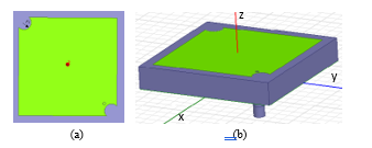 Figure 1: Antenna 1 (a) patch, (b) side view
2.2. Antenna 2
Antenna 2 has 4 identical quarter-circular slots in patch (see Figure 2). These slots are located at all patch corners. Radius of quarter-circles is given by r1. The structure’ s operation range is 1.4101 GHz – 4.5791 GHz (FB=105.82%). Antenna feed is placed at (8, 9) mm.
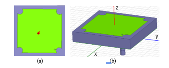 Figure 2: Antenna 2 (a) patch, (b) side view
2.3. Antenna 3
Antenna 3 has 2 identical semi-circular slots in the patch. These slots are located in the middle of two patch edges. The antenna is shown in Figure 3. Semi-circle radius is given by r1. The structure’ s operation range is 1.3287 GHz – 4.0406 GHz (FB=101.02%). Antenna feed is placed at (10, 6) mm.
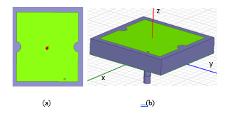 Figure 3: Antenna 3 (a) patch, (b) side view
2.4. Antenna 4
Antenna 4 has 4 identical semi-circular slots in the patch. These slots are located in the middle of all patch edges. The antenna is shown in Figure 4. Semi-circle radius is given by r1. The structure’ s operation ranges are 1.3543 GHz – 2.3231 GHz (FB=52.69%), and 2.8465 GHz – 4.1123 GHz (FB=36.38%). Antenna feed is placed at (7, 9) mm.
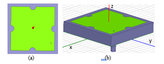 Figure 4: Antenna 4 (a) patch, (b) side view
2.5. Antenna 5
Antenna 5 has 2 identical semi-circular slots in the patch. These slots are located in the middle of two patch edges. The antenna is depicted in Figure 5. Semi-circle radius is given by r2 (5 mm). The structure’ s operation ranges are 1.2659 GHz – 2.1436 GHz (FB=51.49%), and 2.7428 – 4.6657 GHz (FB=51.91%). Antenna feed is placed at (7, 9) mm.
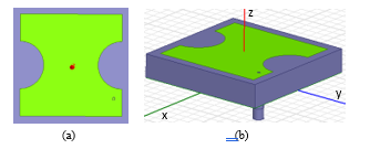 Figure 5: Antenna 5 (a) patch, (b) side view
2.6. Antenna 6
Antenna 6 has 4 identical semi-circular slots in the patch. These slots are located in the middle of all patch edges. The antenna is illustrated in Fig. 6. Semi-circle radius is given by r2. The structure’ s operation range is 1.3465 GHz – 1.8263 GHz (FB=30.24%). Antenna feed is placed at (5.7, 5.3) mm.
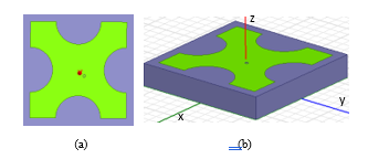 Figure 6: Antenna 6 (a) patch, (b) side view
3. Simulation Results
Simulation results regarding the antenna perormance parameters such as return loss, gain, and radiation pattern are presented for the designed antennas. The return loss and radiation pattern parameters are expressed in dB while the gain values are denoted in dBi. Radiation efficiency and total efficiency values are given in linear scale. Operation frequencies of interest are 1.9 GHz for PCS, 2.1 GHz for 3G, 2.45 GHz for WiFi/WLAN/Bluetooth, 2.6 GHz for LTE and 1.8 GHz for GSM-1800. Table 1 shows the the operations that the antennas are suitable for.
Table 1: Antennas and operations they are suitable for
| Antenna | Operation |
| Antenna 1, 2, 3, 4 | PCS, 3G, WiFi/WLAN/Bluetooth, LTE |
| Antenna 5 | PCS, 3G |
| Antenna 6 | GSM-1800 |
3.1. Results for Antenna 1
Return loss of antenna 1 is given in Figure 7. Maximum gains at 1.9 GHz, 2.1 GHz, 2.45 GHz and 2.6 GHz are 0.087 dBi, 0.055 dBi, 0.052 dBi and 0.058 dBi, respectively. Radiation efficieny values for the same frequencies (in order) are 0.982, 0.975, 0.964 and 0.967, respectively. Total efficiency values for the same frequencies (in order) are 0.923, 0.934, 0.882 and 0.871, respectively.
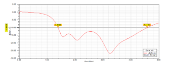 Figure 7: Return loss of antenna 1
Simulated radiation patterns for antenna 1 are shown in Figure 8. Note that radiation pattern plots represent the radiation intensity for all antennas.
3.2. Results for Antenna 2
Return loss of antenna 2 is given in Figure 9. Maximum gains at 1.9 GHz, 2.1 GHz, 2.45 GHz and 2.6 GHz are 0.097 dBi, 0.059 dBi, 0.044 dBi and 0.045 dBi, respectively. Radiation efficieny values for the same frequencies (in order) are 0.985, 0.981, 0.973 and 0.970, respectively. Total efficiency for the same frequencies (in order) are 0.924, 0.885, 0.842 and 0.856, respectively. Simulated radiation pattern plots are depicted in Figure 10.
3.3. Results for Antenna 3
Return loss of antenna 3 is given in Figure 11. Maximum gains at 1.9 GHz, 2.1 GHz, 2.45 GHz and 2.6 GHz are 0.085, 0.042, 0.047 and 0.066 dBi, respectively. Radiation efficieny values for the same frequencies (in order) are 0.968, 0.989, 0.982 and 0.974, respectively. Total efficiency values for the same frequencies (in order) are 0.911, 0.940, 0.881 and 0.872, respectively. Simulated radiation pattern plots are shown in Figure 12.
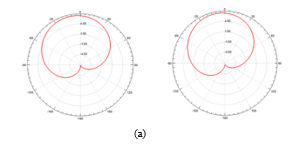
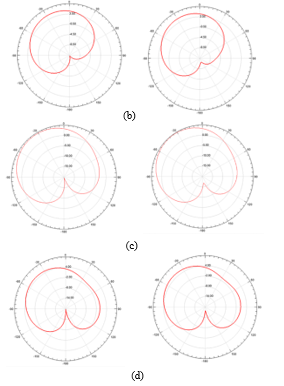 Figure 8: Antenna 1 radiation patterns of ϕ=0ᴼ (left), and ϕ=90ᴼ (right): (a) f=1.9 GHz, (b) f=2.1 GHz, (c) f=2.45 GHz, (d) f=2.6 GHz
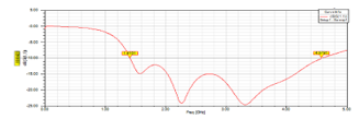 Figure 9: Return loss of antenna 2
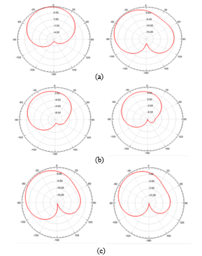
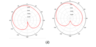 Figure 10: Antenna 2 radiation patterns of ϕ=0ᴼ (left), and ϕ=90ᴼ (right): (a) f=1.9 GHz, (b) f=2.1 GHz, (c) f=2.45 GHz, (d) f=2.6 GHz
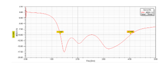 Figure 11: Return loss of antenna 3
3.4. Results for Antenna 4
Return loss of antenna 4 is given in Figure 13. Maximum gains at 1.9 GHz, 2.1 GHz, 2.45 GHz and 2.6 GHz are 0.074, 0.079, 0.082 and 0.087 dBi, respectively. Radiation efficiency values for the same frequencies (in order) are 0.978, 0.988, 0.974 and 0.982, respectively. Total efficiency values for the same frequencies (in order) are 0.935, 0.948, 0.847 and 0.841, respectively. Simulated radiation pattern plots are illustrated in Figure 14.
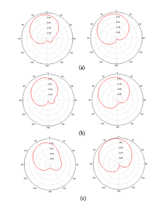
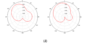 Figure 12: Antenna 3 radiation patterns of ϕ=0ᴼ (left), and ϕ=90ᴼ (right): (a) f=1.9 GHz, (b) f=2.1 GHz, (c) f=2.45 GHz, (d) f=2.6 GHz.
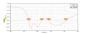 Figure 13: Return loss of antenna 4
3.5. Results for Antenna 5
Return loss of antenna 5 is given in Fig. 15. Maximum gains at 1.9 GHz and 2.1 GHz are 0.053 and 0.062, respectively. Radiation efficiency values for the same frequencies (in order) are 0.984 and 0.997, respectively. Total efficiency values for the same frequencies (in order) are 0.958 and 0.910, respectively. Simulated radiation pattern plots are given in Fig. 16.
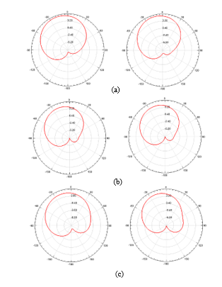
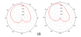 Figure 14: Antenna 4 radiation patterns of ϕ=0ᴼ (left), and ϕ=90ᴼ (right): (a) f=1.9 GHz, (b) f=2.1 GHz, (c) f=2.45 GHz, (d) f=2.6 GHz
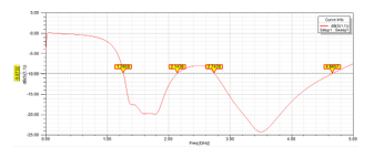 Figure 15. Return loss of antenna 5
3.6. Results for Antenna 6
Return loss of antenna 6 is given in Figure 17. Radiation efficiency and total efficiency values at 1.8 GHz are 0.985 and 0.912, respectively. Simulated radiation pattern plots are illustrated in Figure 18.
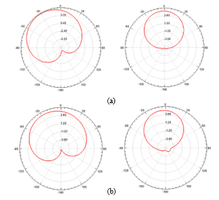 Figure 16: Antenna 5 radiation patterns of ϕ=0ᴼ (left), and ϕ=90ᴼ (right): (a) f=1.9 GHz, (b) f=2.1 GHz
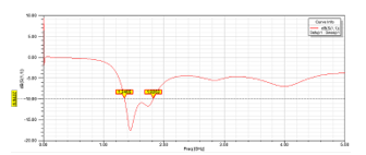 Figure 17: Return loss of antenna 6
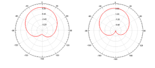 Figure 18: Antenna 6 radiation patterns at f=1.8 GHz: ϕ=0ᴼ (left), and ϕ=90ᴼ (right)
4. Discussion
Considering the designed antennas, antenna 1, antenna 2, antenna 3 and antenna 4 are suitable for PCS, 3G, WiFi/WLAN/Bluetooth and LTE. Antenna 5 cannot be used for WiFi/WLAN/Bluetooth and LTE operations due to the related frequency bands. Likewise, antenna 6 is only suitable for GSM-1800 operation. Highest fractional bandwidth (106.74%) is obtained for antenna 1. Operation frequency band of antenna 2 is shifted upward compared to that of antenna 1. Similarly, an upward band shift is clear by taking into account the frequency band of antenna 3 as well as the lower and upper frequency ends of antenna 4. Also, an increase in the lower end of frequency band is clear by comparing antenna 5 and antenna 6 frequency values. This occurs because the antenna capacitance decreases as the slot dimension increases, which yields larger resonant frequencies. Note that as the antenna capacitance decreases, the resonant frequency increases. Maximum gains for all cases are similar. The case for PCS operation of antenna 2 has the highest maximum gain (0.097 dBi). Directional radiation patterns are obtained for all cases. Maximum radiation occurs in boresight for PCS operation of antenna 6. We have the highest radiation levels for PCS operation of antenna 2. Radiation efficiency and total efficiency values are relatively high indicating that the usage of a substrate with a high dielectric constant does not significantly lower the efficiencies. Simulations of surface current distribution on the antenna patches for different phase angles at all application frequencies reveal multiple current paths, which yield resonances. Note that the resonance occurs when the path length of the current equals to half of the resonant wavelength in the dielectric material. More information on current path length and resonant frequency analysis can be found in [10]. In order to verify the reliability of the simulation tool HFSS, following procedure is performed: Based on the theoretical calculations of patch width and patch length by using a resonant frequency [11], a reverse computation is carried out for the slotless microstrip patch antenna: The resonant frequency is analytically computed as 2.088 GHz by using the known values of the width and relative dielectric constant. Then, the length of the patch is computed as 15.48 mm by utilizing the calculations of effective length and extension length. Analytically computed values of the resonant frequency and the patch length are consistent with the simulated values. Note that a simulated resonant frequency for the slotless microstrip patch antenna is found to be 2.05 GHz.
5. Conclusion
Six square microstrip patch antennas with slots in patch are designed. Impact of quarter-circular and semi-circular patch truncations on the antenna performance parameters is examined. Results regarding the simulations of return loss, maximum gain, radiation pattern, radiation efficiency and total efficiency are presented. Optimizations are carried out in order to improve impedance matching.
- C. Dogusgen Erbas, B. Demirbas, C. Yaman and A. Okatan, “Design and comparison of microstrip patch antennas with different patch shapes for wireless communications” in 11th International Conference of Electrical and Electronics Engineering, 646-650, 2019, doi: 10.23919/ELECO47770.2019.8990499.
- M. Kumar, V. Nath, “Introducing multiband a wideband microstrip patch antennas using fractal geometries: development in last dacade”, Wireless Pers. Commun., 98, 2079-2105, 2018, doi: 10.1007/s11277-017-4965-x.
- C. A. Balanis, “Antenna theory: analysis and design”, Wiley, 2012.
- G. Sami, M. Mohanna, M. L. Rabeh, “Tri-band microstrip antenna design for wireless communication applications”, NRIAG Journal of Astronomy and Geophysics, 2, 39-44, 2013, doi: 10.1016/j.nrjag.2013.06.007.
- M. R. Ahsan, M. T. Islam, M. H. Ullah “A microstrip-fed reformed rectangular shape slotted patch for simultaneous operation in GPS and WLAN bands”, Microwave and Optical Technology Letters, 57, 2204-2207, 2015, doi: 10.1002/mop.29290.
- C. Y. D. Sim, B. H. Yang, “A single layer dual-band CP microstrip antenna for GPS and DSRC applications”, Journal of Electromagnetic Waves and Applications, 22, 529-539, 2008, 10.1163/156939308784150308.
- J. Kaur, Nitika and R. Panwar, “Design and optimization of a dual-band slotted microstrip patch antenna using Differential Evolution Algorithm with improved cross polarization characteristics for wireless applications”, Journal of Electromagnetic Waves and Applications, 33, 1427-1442, 2019, doi: 10.1080/09205071.2019.1612283.
- W. W. Li, Q. H. Li, Y. Meng, J. Y. Wang, et. al. , “A broadband microstrip patch antenna with multiple open slots”, Microw. Opt. Technol. Lett., 61, 626-632, 2018, doi: 10.1002/mop.31646.
- N. Hassan, Z. Zakaria, W. Y. Sam, I. N. M. Hanapiah, “Design of dual-band microstrip patch antenna with right-angle triangular aperture slot for energy transfer application”, International Journal of RF and Microwave Computer-Aided Engineering, 29, 1-11, 2018, doi: 10.1002/mmce.21666.
- R. Varma, J. Ghosh and R. Bhattacharya, “A compact dual frequency double U-slot rectangular microstrip patch antenna for WiFi/WiMAX”, 59, 2174-2179, 2017, doi: 10.1002/mop.30705.
- C. A. Balanis, “Antenna Theory: Analysis and Design”, Wiley, 2005.