Dry Sliding Wear Behaviour of ZA27/ MoS2 Metal Matrix Composite

Adv. Sci. Technol. Eng. Syst. J. 6(3), 263–270 (2021);
 DOI: 10.25046/aj060329
The Present work is to investigate effect of dry sliding wear behaviour of ZA27 base alloy, after reinforcing it with Molybdenum Di Sulphide (MoS2) particles from 0% to 4% in five steps. To examine the wear behaviour of both reinforced and un-reinforced material, dry or unlubricated pin on disc tests were conducted. These tests were conducted at varying speeds and loads of 1.5m/s,3m/s, 4.6m/s, 6.15 m/s and 5N, 10N, 20N and 25Nrespectively with a constant sliding distance of 1000m. The results revealed that, MoS2 reinforced ZA27 alloy showed less wear loss as compared to base ZA27 alloy. Delamination, abrasion, and adhesive wear were observed at high speed and load. Worn surface of tested specimen were analysed and examined through Scanning Electron Microscope (SEM). To confirm presence of Molybdenum disulphide in prepared material, Energy Dispersion X-ray (EDX) test is carried out for 4% of Molybdenum disulphide reinforced ZA-27 material.
1. Introduction
From the last few decades, metal matrix composite has played a vital role in the improvement of physical and mechanical properties of traditional materials. Also, it plays a significant impact from an economic point of view due to its wide range of application in engineering material. It will always be a choice of many researchers to further improve its performance through changing or varying its composition[1]-[5]. Maximum work was done on the various Aluminium series in the field of non-ferrous metal. In comparison with aluminium less scope is given to other non-ferrous metal like brass, copper, magnesium, and zinc.
Pure zinc cannot compete with other non-ferrous material. But zinc when reinforced with the various proportion of aluminium, at certain composition, it can be observed that zinc properties improved to such level that it can be easily compete with other traditional non-ferrous material such as copper, brass, bronze, aluminium and also cast iron in the field of moderate load, medium speed and moderate operating temperature, generally ZA 27 applied for bearing and tribo material [6]-[9]. Many researchers have experienced that 27% of aluminium reinforcement shows good mechanical and physical properties compared to other percentages. ZA27 stands for zinc containing 27 percentage of aluminium.ZA27 possesses tribo-mechanical properties, eco-friendly, excellent fluidity and foundry castability as well as low initial cost. Resistance to corrosion and high mechanical strength at room temperature are other admirable properties of ZA27 alloy [10]-[12]. These exceptional properties have motivated the researchers to further enhance its mechanical and tribological properties through reinforcing ZA 27alloy with a different metal, non-metal and ceramics with varying current alloy composition or changing method of casting. As a result, author [10],studied wearing of ZA 27 after Reinforcing with 2% graphite. In [13], reinforced graphite with ZA 27, varying its size and percentages to study it’s mechanical properties. In [14], ZA 27is experimented with zircon by its varying percentage. Author [7] , reinforced small quantity of Manganese (Mn) with a weight range of 0.1% to 0.7% in ZA27 metal using the normal casting method. In paper [15], tribological test is conducted after reinforcing Mn content with ZA27 alloy. In paper [16], Za27 with 2% Magnesium (Mg) material is tested. Author [12], presented the paper on results of tribological investigations of composites with substrate made of the ZA-27 alloy reinforced by the Al2O3. Author [17], studied combined effect of reinforcement both 5% SiC and 1% Graphite particle in Za27 alloy. The combined effect of silicon, Silicon Carbide, graphite and copper with various percentage on ZA27 alloy is studied in another researcher [6] . Author [9], worked on reinforcing glass fibers of weight 1% to 5% in ZA27 alloy using the compo-casting method. In [18] ,examined the effect of various composition of titanium on ZA 27 alloy. Author [19], fabricated ZA27 alloy with 2% of TiB2 particulates. In such a way, researchers have experimented with various reinforced materials and various method to improve the mechanical and tribological properties of ZA 27 alloy.
Molybdenum disulphide is an inorganic compound which is used as a solid lubricant, it is used in relatively high temperature when compared to graphite [20]. It has experimented with polymer and other organic material in the field of polymer matrix composite. It has also been observed that addition of Molybdenum disulphide has improved the tribological properties of high density poly ethylene and Polyetherether ketone (PEEK) composite in vacuum [21], it is also experimented with Phenolic resin to improve its mechanical and tribological properties [22], but rare literatures are found, in which Molybdenum disulphide was used as reinforcement material with Zinc Aluminium 27 (ZA -27) Metal Matrix composite. Since ZA 27 alloy is also applied in tribo material like bearing and bushing, which is subjected to frictional heat, MoS2 is possess good lubricating property, generally it is used externally, to remove frictional heat between contact surface. Till now with mentioned composition of ZA 27 (Sn 1-2%,Cu 0.5%, 27% Al, balance zinc), no literature is found in which MoS2 is used as reinforced material with ZA27 .
2. Experimentation
2.1. Material
The metal matrix selected for the present work is Zinc Aluminium alloy in which the proportion of Aluminium is 27%. The importance of ZA 27 alloy has already been discussed in the introduction. Composition of ZA27 is, Tin between 1% to 2%, Copper 0.5%, Aluminium 27% and remaining is zinc. Molybdenum disulphide (MoS2) particle is used as reinforcement component which has particle size 40 micron with the average density of 5.6gm/mm3. MoS2 fabricated with base ZA27 alloy with increasing proportion from 0 to 4% with an increment step of 1 %. Steel crucible is used in an electric heating furnace to melt alloy. A stirrer is attached with an adjustable speed motor which is used for stirring purpose. Skum powder or cleaning powder added to the molten metal in order to remove slag and flux.
2.2. Preparation of Specimen
Specimen for wear testing has prepared with the help of the stir casting method [23]. Based on the furnace’s crucible size, a calculated amount of ZA 27 is weighed and placed in the crucible. Heating of crucible is carried out at a constant temperature of 600oC until the solid ZA27 is converted into a liquid phase. The molten matrix is cooled to a mixing temperature of 490oC, at which stirring of molten metal was carried out with the help of a stirrer, which operates at the speed of 1 to 500 rpm. Based on the weight of molten ZA27, 1% MoS2 particle was weighed and then poured in stirring liquid which is operated at speed of 200 rpm. Gradually speed of the stirrer is increased to a range of 320 to 350 rpm after mixing of reinforcement material. The Stirring of molten metal is continued for 5 minutes. Before pouring molten metal into a mould, a circular mould that is made of cast iron is heated. Heated molten metal is poured into the pre-heated mould. The same procedure is repeated for reinforcement of 2,3and 4 percentage of MoS2 particle. Mould is allowed to cool at room temperature, as a result, the molten metal inside the mould is solidified. Casted metal from the mould was removed and machined according to ASTM G99 standard size. Tested specimen of diameter (d) 10 mm and length of 1.5d to 2d is prepared. The end surface of the specimen is polished and flattened with the help of an emery sheet of 1000 size. Finally mirror polished surface at the end of the specimen is obtained for wear testing.
2.3. Wear testing of specimen.
Pin on disc apparatus (as shown in Figure 1:) is used to investigate the dry sliding wear behaviour of flatted end, mirror polished ZA27, ZA27/1%MoS2 ZA27/2%MoS2, ZA27/3%MoS2 and ZA27/4%MoS2 specimens. Load, sliding distance, and sliding speed are parameters considered for present wear testing. The selected value for loads is 5N, 10N, 20N and 25N. Sliding distance are 1.53m/s,3m/s, 4.6m/s and 6.15m/s with constant sliding distance of 1000m is maintained for both parameters. All tests is conducted at room temperature; details are shown in Table 2.1. During the test, the initial weight of the composite is measured using a weighing machine having the least count of 0.0001g. The testing pin is applied with a defined load, against the EN32 steel disc. The pin is pressed against the rotating disc at a track diameter of 98 mm at a specific speed, and a constant sliding distance of 1000m. The disc is rotated for prescribed speed, after running at a specific sliding distance, the rotating disc is stopped and tested specimen taken out from the setup. The final weight of the worn-out specimen is measured. The procedure is repeated to all specimen. Each specimen has experimented with three times and the average weight loss of each specimen is taken for wear analyse. Graph of the average wear loss of tested specimen vs. varying load and speed were plotted to examine the overall behaviour of all specimens. During testing, the specimen projected its particle on countersurface, as a result, a circular thin track of specimen is formed on the rotating disc due to the relative motion and difference of hardness between countersurface and specimen. As the specimen was softer than the rotating disc, the worn particles of a specimen are projected on the rotating disc. This analyses the counter-surface which is shown in Figure 2.
Table 1: Wear testing parameter
| Pin material | ZA-27 with 0%, 1%, 2%, 3%and 4% MoS2 |
| Disc Material ( rotating) | EN32 steel Disc usedas counter-body ( 65 HRC) |
| Track diameter | 98mm |
| Sliding speed m/s | 1.53, 3, 4..6,6.15 |
| Load (N) | 5,10,20 and 25 |
| Sliding distance | 1000m |
| Temperature | Room temperature |
3. Experimental Results
3.1. Effect of Applied Load on Wear Loss
Prepared specimens of various compositions are tested at different loads of 5N, 10N, 20N and 25N at a constant sliding distance of 1000m and a constant sliding speed of 4.6m/s. The difference between the initial and final weight of each specimen was tabulated. Using obtained value graph of Wear loss in milligram (mg) versus various load in newton has generated as shown in Figure 3. It has been observed from the graph (Figure 3) that, as the load on the specimen is increased, the rate of wear is also increased for both molybdenum disulphide reinforced and unreinforced material. It has also been noticed from the above graph that unreinforced materials lost their maximum weight during the wear test when compared to reinforced material. At a lower load of 5N, mild wear was observed for reinforced material compared to a little high degree of wear was observed for unreinforced material. This trend of increasing weight loss due to wearing continues for the load of 10N and 15N, to mild weight loss to medium weight loss. The specimen was tested up to a load of 25 N, significant results have been seen at a higher load of 25N for the unreinforced material. Worn surface of specimen deformed. Worn material comes out and attached at the circular end of the specimen. Simultaneously when observed the behaviour of various reinforced materials, all reinforced composition showed the better results when compared to unreinforced specimen. Among composite specimen, 4% and 3% of the reinforced specimen showed good wear resistant compared to 1 % and 2% of the reinforced composite and also 3% and 4% of reinforced composite showed nearly repeated result and simultaneous experienced higher wear resistance as compared to unreinforced ZA27 and ZA27 contains lower composition MoS2 like 1% and 2 %.From figure 3 it can be observed that there is an increase in wear-resistant as increased in the composition of MoS2 in ZA 27, but There is slight breakage of trend that can be seen at an applied load of 25N, speed of 4.6 m/s and sliding distance of 1000m. The mixed result is observed for 3% and 4% reinforced composite at a higher load of 25N.
3.2. Effect of sliding speed on wear loss
After various load parameters, tests are conducted based on the sliding speed parameter. Prepared specimens of various compositions of 0%, 1%, 3% and 4% of molybdenum disulphide are tested at various sliding speed of 1.5m/s, 3m/s, 4.6 m/s 6.1m/s at constant sliding distance of 1000m and constant load of 20N. The difference between the initial and final weight of each specimen is tabulated. Using obtained value, the graph of wear loss in milligram versus various sliding speed in meter per second is generated as shown in Figure 4. It has been observed from the graph (Figure 4) that, as the sliding speed of the specimen is increased, the rate of wear is also increased for both molybdenum disulphide reinforced and unreinforced material. It has been noticed from the above graph that, unreinforced material lost its maximum weight during the wear test when compared to reinforced material up to a speed of 4.6m/s. But after 4.6m/s speed, remarkable results were noticed that 4% and unreinforced material was worn out much compared to both 3% and 1% of reinforced molybdenum disulphide materials at speed of 6.15m/s. From the above results and graphs of both varying speed and varying load, it can be concluded that addition of molybdenum disulphide is not more than 3 % percentage for higher speed of 6.15m/s and medium speed of 4.6m/s, 3 to 4 percentage of molybdenum disulphide can be used as reinforced material. Somewhat similar results have been found during varying load from 5N to 25 N. At low speed of 1.5m/s mild wear were observed for both molybdenum disulphide reinforced and unreinforced specimens. However, as the sliding speed increased proportionally wear rate has also increased and weight loss due to wear also increased. At a higher speed of 6.15m/s, the high degree of wear and tear is observed, as a result, the worn surface smeared and highly deformed than the actual dimension of the specimen. During the process, heavy vibration and noise noticed. Transfers of pin material on contact disc were also observed during testing of all specimens. It can be seen from both the graph of Figure 2 and Figure 3, 3% of percentage reinforced molybdenum disulphide has a more positive effect on the base metal ZA27 when compared with unreinforced as well as various reinforced material when tested for a parameter of varying load and varying speed.
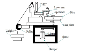 Figure 1: Schematic diagram of the dry sliding wear testing apparatus
 Figure 2: Analyses of countersurface during wear
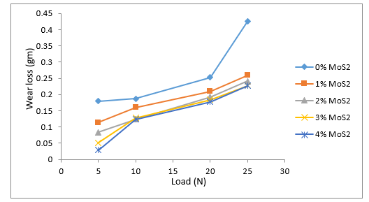 Figure 3: Variation of wear loss with varying applied Load for constant sliding of 1000m and sliding speed of 4.6m/s.
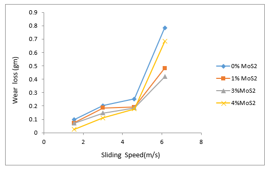 Figure 4: Variation of wear loss with varying Sliding speed for constant sliding distance of 1000m and load of 20N
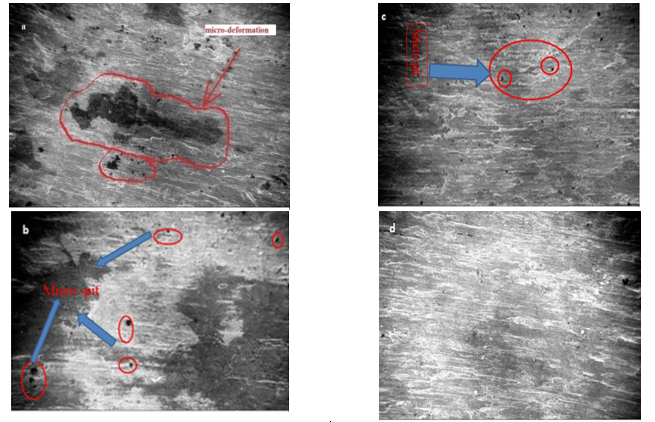 Figure 5: SEM image (100 μm size) of worn surface for the specimen for varying sliding speed of 4.6 m/s constant load of 20N and sliding distance of 1000m. a) 0% MoS2 Figure b)1%MoS2,Figure c)3%MoS2Figure d)4%MoS2
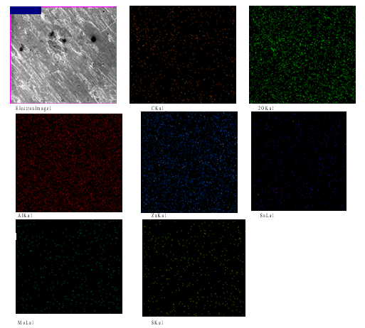
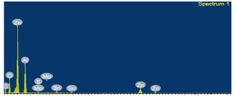 Figure 6: Energy Dispersion X-ray (EDX) report for 4% MoS2 reinforced ZA-27 material
3.3. SEM Analyses of worn surface
Scanning electron microscope (SEM) image of the worn surface was taken for molybdenum disulphide reinforced and unreinforced ZA27 specimen, for a load of 20 N, speed of 4.6 m/s and distance of 1000 m. Interesting results are observed from Figure 3, for varying speed of 4.6m/s, at that speed, 4% MoS2 reinforced specimen shows better results when compared to 3% MoS2 and 1% MoS2 reinforced material as well as unreinforced material. As a result, at that point, SEM analyses were carried out. As sliding speed increases wear rate also increases, this is already explained in the previous section. But after observing all four SEM images distinct changes can be seen between unreinforced and reinforced ZA27 base metal. From graph 2 and 3, it can be observed, unreinforced specimen exhibits poor wear performance compared to all reinforced specimen. Figure 5 a) shows SEM image of unreinforced material is not smooth. Micro debris appeared during operation between the rotating steel disc and tested specimen. During cyclic rotation of the disc, the micro-debris appeared between contact surface that leads to abrasive wear occur. As a result, due to brittle fracture, micro deformation can be seen in Figure 5(a), due to expelled of microchips from the worn surface and also minute damage was observed for the unreinforced specimen, from the SEM image shown in Figure 5(a). As the percentage of MoS2 was increased in base metal, the level of damage is reduced which can be seen from SEM image of 1%MoS2 in Figure 5(b), 3% MoS2 in Figure 5(c) and 4% MoS2 in Figure 4(d) for the speed of 4.6m/s. But crushed micro debris attached to the worn surface of both reinforced and unreinforced material during rotation of the disc. As the percentage of MoS2 increased, wear rate in composite specimen up to load of 20 N, speed of 4.6 m/s and distance of 1000m decreased repeatedly for all MoS2 reinforced specimens compared to the unreinforced specimen and each specimen was tested thrice to get repeatability of the result. This attributed to the presence of MoS2 particle which acted as a lubricating agent which is projected out from worn specimen that reduces heating effect which occurred due to friction between pin and disc, similar findings were observed for Graphite from other researchers [24][10][1]. A similar observation can be seen from SEM image that, with the addition of reinforced material, comparatively more refined image, relatively lesser micro-deformation, and minimization of extraction micro-flake from the worn surface due to friction and heat can be observed. Comparing Figure 5(a) and Figure 5(b) , variation in size of damage in the form of micro-pit is observed at some portion of the surface as a result of the detachment of micro particles from the specimen during testing due to abrasive wear.Interestingly, the size of the micro-pit and the number of micro-pits is reduced for 1% MoS2 reinforced specimen when compared to the unreinforced specimen as shown in the SEM image, which can be observed from Figure 5 (b) and 5(a). Both sizes of pits are marked with the help of a circle in Figure 5(a) and Figure 5(b). Further increase in the proportion of MoS2, further reduced in size and the number of micro-pits that is shown in Figure 4 (c). When observed for 4% of MoS2 reinforced image, a more refined surface can be seen in Figure 4(d) as compared to all remaining 3 images as shown in Figure 5(a), 5(b) and 5(c). The observed portion of the micro-deformed surface in Figure 5(a) and pits surface in Figure 5(b) and 5(c) are marked with the help of the ellipse in the SEM image.
3.4 EDX Analyses
To confirm, the presence of Molybdenum disulphide in ZA 27 based metal, energy dispersion X-ray (EDX) image taken for one of the reinforced specimens. For that 4%, Molybdenum disulphide reinforced ZA 27 used. The EDX image of 4 percentage of MoS2 reinforced specimen can be seen in Figure 6. From the image, it can be seen that molybdenum and sulphide are distributed in the same orientation and location. It can also be concluded that there is no separation occur between Molybdenum particle and sulphur particle during casting due to high temperature. From electron image, it is observed that for 700 micro-meter sizes of worn surface more molybdenum was confirmed when compared to tin element.
4. Discussion
The graphs of applied load and sliding speed vs. weight loss due to wearing are plotted as shown in Figure 3 and Figure 4 respectively. In both graphs, it can be seen that, as applied load and sliding speed increases, the wear rate also increases. MoS2 reinforced specimen shows a different level of wear rate depending upon the quantity of its reinforced alloy. However, interestingly, it has been observed that, up to some limit, at a sliding speed of 4.6m/s, reinforced material revealed less wear rate when compared to unreinforced material. Tests were conducted with increasing level of the parameter for applied load from 5N to 25N and sliding speed from 1.56 m/s to 6.15m/s. The end surface area of the stationary pin completely contacts with a rotating steel disc. Due to the difference in hardness and strength as well as relative motion between pin and disc, frictional heat generation was observed when a heated pin is taken out from the wearing machine after running it for a specific time. During operation, heavy noise and vibration were observed, which increased with increasing applied load and sliding speed of the pin for both molybdenum disulphide reinforced and unreinforced specimen. A similar situation was reported by other researchers [25]. During the low applied load of 5N and low sliding speed of 1.56 m/s, at a constant sliding distance of 1000m, the smooth polished surface of the pin turned to rough scratches. Micro or powder-like particles appeared from the pin during rotation of the disc, which are in contact with each other due to wear and friction. These particles are attached and smeared, abraded surface and spread over the track on which pin rotates during each cycle of revolution. Generally, abrasive type of wear occurred, as a result, weight of prepared specimen was reduced due to abrasive wear mechanism. But from both varying applied load and sliding speed graphs, composite material revealed better result when compared to unreinforced ZA 27 alloy for all parameter of speed and load. This can be attributed to the presence of Molybdenum disulphide particles. During operation, micro-particles were projected out from the specimen due to continuous shearing of surface on steel disc, simultaneously frictional heat was generated due to relative motion. In addition, it has observed that, at higher sliding speed and applied load, the material come out in the form of macro-debris and flakes faster rate than lower applied load and sliding speed, which caused a decrease in a final weight of the specimen. But the decrease in wear rate observed from the mentioned graph 3 and graph 4 for molybdenum disulphide reinforced ZA27 material compared to unreinforced ZA 27 material. During the testing, materials were projected out from the specimen, in the form of minute flakes or chips or small particles or debris depending upon the degree of applied load and sliding distance.
During the projection, in the case of a reinforced specimen, molybdenum disulphide was present, also come out from the specimen transform to the rotational track of the disc. As a result, molybdenum disulphide acts as a lubricating agent, which minimizes frictional heat, generated due to the relative motion between rotating disc and pin. Molybdenum disulphide smeared on the abraded surface, which projected out from the rotating pin, which is pressed against rotating disc due to applied load. It acts as a tribo-layer between rotating disc and pin, meaning the projected molybdenum disulphide will enter between stationary pin, which is compressed against the disc, which reduces the level of heat generation, which has not occurred for unreinforced ZA27 base alloy [27]. Similar findings are reported from other researchers regarding the reinforcement of graphite [10][1][26]. Similarly, it can also be seen from Scanning Electron Microscope (SEM) images from Figure 5 (a) to 5 (d). Where unreinforced specimen is shown in Figure 5 (a) observed more damage and cloud-like surface(marked in red colour), when compared to the other images that are shown in Figure 5 (b) for 1%MoS2 reinforced ZA-27, Figure 5 (c) for 3% MoS2 reinforced ZA-27,and Figure 5 (d) for 4% MoS2reinforced ZA-27. After observing the images from Figure 5, it can be seen that, when the percentage of molybdenum disulphide increased, the size of the damage is reduced, fewer pits generated due to debris when compared to images shown in Figure 5(b), less uneven surface was observed in Figure 5 (c) and Figure 5(d) which was having reinforcement percentage 3% and 4% of molybdenum disulphide respectively compared to the unreinforced ZA-27 base alloy that is shown in Figure 5 (a) and 1% Molybdenum disulphide reinforced ZA 27 alloy shown in Figure 5(b). To confirm the presence of Molybdenum disulphide in reinforced ZA 27 alloy, one of the reinforced specimens was tested with Energy Dispersion X-ray (EDX) test. Energy Dispersion X-ray test was carried out for ZA27 alloy which was reinforced with 4% molybdenum disulphide. The image of the test as shown in Figure 6 confirmed the presence of MoS2 in reinforced metal. It has also been observed that Molybdenum and sulphur are present at the same location. During operation, minute pits were generated due to interaction of specimen with projected debris which resulted in that shear stress will occur and that pit nucleates during rotation of the disc. Simultaneously, subsurface cracks are occurred in some specimen due to the removal layer in the form of flacks or chips as a result, severe abrasive wear was observed after the sliding speed of 4.6 m/s, at a constant sliding distance of 1000m and an applied load of 20N. Unambiguous results were observed after the speed of 4.6 m/s. Interestingly, at the speed of 6.15m/s, 3 % reinforced Molybdenum disulphide ZA 27 specimen showed the good result when compared to the unreinforced ZA 27 base alloy and similarly when the same composition is tested for varying load of 5N to 25N, 3% reinforced Molybdenum disulphide showed the better result at a higher applied load of 25N, when compared to unreinforced ZA 27 base alloy and some Molybdenum disulphide reinforced specimen for a constant sliding distance of 1000m and sliding speed of 4.6m/s. At a higher speed of 6.15m/s more noise and vibration occurred and more frictional heat was generated due to the relative motion between the pin and rotating steel disc. Due to frictional heat, applied pressure as well as surface contact area increases due to plastic deformation. As a result, attached debris and particles cluster are accumulated at the circular edge of the tested pin.
5. Conclusion
Present work, the investigation has been done on dry sliding wear behavior of ZA 27 base metal and ZA 27/MoS2 reinforced metal under varying applied load and sliding speed conditions. It is also observed from the above-mentioned result that, MoS2 reinforced ZA27 specimen having more wear resistant as compared to the unreinforced ZA27 specimen in both varying load and speed. Up to 3% MoS2 reinforced ZA 27 showed good wear resistant as compared to other percentages of reinforcement. But increasing in MoS2 content beyond 4% for the higher load of 25N and the speed of 6.25m/s at a constant sliding distance of 1000m, there is a decrease in wear resistant is observed as compared to other reinforcement percentages, still better than unreinforced ZA27 alloy. Addition of molybdenum disulphide decrease wear rate of reinforced ZA 27 metal through smearing Molybdenum disulphide coat at the interface between the pin and the counter face. During medium load and speed, abrasion wear observed while at high speed, Delamination wear occurred due to nucleation of subsurface crack.
Acknowledgement
I thank all who directly and indirectly helped me in casting, testing of specimens and guided me to write a research article, particularly my father in law M.H.R.Khasimi who supported morally, ethically and continuously encouraged me to do research work.
Conflict Of Interest
“On behalf of all authors, the corresponding author states that there is no conflict of interest”
- S. Basavarajappa, G. Chandramohan, K. Mukund, M. Ashwin, M. Prabu, “Dry Sliding Wear Behavior of Al 2219 / SiCp-Gr Hybrid Metal Matrix Composites,” Journal of Materials Engineering and Performanc, 15(December), 668–674, 2006, doi:10.1361/105994906X150803.
- F. Gul, M. Acilar, “Effect of the reinforcement volume fraction on the dry sliding wear behaviour of Al-10Si/SiCp composites produced by vacuum infiltration technique,” Composites Science and Technology, 64(13–14), 1959–1970, 2004, doi:10.1016/j.compscitech.2004.02.013.
- A.M. Davidson, D. Regener, “A comparison of aluminium-based metal-matrix composites reinforced with coated and uncoated particulate silicon carbide,” Composites Science and Technology, 60, 865–869, 2000, doi:10.1016/S0266-3538(99)00151-7.
- B. Venkataraman, G. Sundararajan, “Correlation between the characteristics of the mechanically mixed layer and wear behaviour of aluminium, Al-7075 alloy and Al-MMCs,” Wear, 245(1–2), 22–38, 2000, doi:10.1016/S0043-1648(00)00463-4.
- Y. Iwai, T. Honda, T. Miyajima, Y. Iwasaki, M.K. Surappa, “Dry sliding wear behavior of Al 2 O 3 Fiber reinforced aluminum composites,” Composites Science and Technology, 60, 1781–1789, 2000, doi:doi: org/10.1016/S0266-3538(00)00068-3.
- R. Auras, C. Schvezov, “Wear Behavior , Microstructure , and Dimensional Stability of As-Cast Zinc-Aluminum / SIC ( Metal Matrix Composites ) Alloys,” 35(May), 1579–1590, 2004.
- C. Domínguez, M. V. Moreno López, D. Ríos-Jara, “The influence of manganese on the microstructure and the strength of a ZA-27 alloy,” Journal of Materials Science, 37(23), 5123–5127, 2002, doi:10.1023/A:1021016522586.
- B.M.S. SC. Sharma , B.M. Girish, Rathnakar Kamath, “Graphite particles reinforced ZA-27 alloy composite materials for journal bearing application,” Wear, 219, 162–168, 1998, doi:org/10.1016/S0043-1648(98)00188-4.
- S.C. Sharma, B.M. Girish, B.M. Satish, R. Kamath, “Mechanical properties of as-cast and heat-treated ZA-27 alloy/short glass fiber composites,” Journal of Materials Engineering and Performance, 7(1), 93–99, 1998, doi:10.1361/105994998770348098.
- M. Babic, M. Slobodan, D. Džunic, B. Jeremic, B. Ilija, “Tribological behavior of composites based on ZA-27 alloy reinforced with graphite particles,” Tribology Letters, 37(2), 401–410, 2010, doi:10.1007/s11249-009-9535-2.
- M. Babi?, S. Mitrovi?, R. Ninkovi?, “Tribological potencial of zinc-Aluminium alloys improvement,” Tribology in Industry, 31(1–2), 15–28, 2009.
- S. Mitrovi?, M. Babi?, I. Bobi?, “ZA-27 alloy composites reinforced with Al2O3 particles,” Tribology in Industry, 29(3–4), 35–41, 2007.
- K.H.W. Seah, “Mechanical particulate properties composites of cast ZA 27 / graphite,” 16(5), 1–5, 1995.
- S.C. Sharma, B.M. Girish, D.R. Somashekar, B.M. Satish, R. Kamath, “Sliding wear behaviour of zircon particles reinforced ZA-27 alloy composite materials,” Wear, 224, 89–94, 1999.
- V. Algur, V.R. Kabadi, S.M. Ganechari, V. Rao, “Influence of Mn Content on Tribological Wear Behaviour of ZA-27 Alloy,” Materials Today: Proceedings, 4(10), 10927–10934, 2017, doi:10.1016/j.matpr.2017.08.048.
- T.J. Chen, Y. Hao, J. Sun, Y.D. Li, “Effects of Mg and RE additions on the semi-solid microstructure of a zinc alloy ZA27,” Science and Technology of Advanced Materials, 4(6), 495–502, 2003, doi:10.1016/j.stam.2004.01.002.
- K.H.W. Seah, S.C. Sharma, P.R. Rao, B.M. Girish, “Mechanical properties of as-cast and ZA-27 / silicon carbide particulate compositea,” Materials & Design, 16(5), 277–281, 1996, doi:org/10.1016/0261-3069(96)00008-8.
- W. Krajewski, “The Effect of Ti Addition on Properties of Selected Zn-A1 Alloys,” Phys. Stat. Sol, 145, 389–399, 1995.
- Z.G. Li, “Fabrication of in situ TiB 2 particulates reinforced zinc alloy matrix composite,” 121, 1–4, 2014, doi:10.1016/j.matlet.2014.01.050.
- J.P.G. Farr, “Molybdenum disulphide in lubrication. a review,” Wear, 35, 1–22, 1975, doi:10.1016/0043-1648(75)90137-4.
- G. Theiler, T. Gradt, “Friction and wear of PEEK composites in vacuum environment,” Wear, 269, 278–284, 2010, doi:10.1016/j.wear.2010.04.007.
- G. Yi, F. Yan, “Mechanical and tribological properties of phenolic resin-based friction composites filled with several inorganic fillers,” Wear, 262, 121–129, 2007, doi:10.1016/j.wear.2006.04.004.
- S. Amirkhanlou, B. Niroumand, “Synthesis and characterization of 356-SiC p composites by stir casting and compocasting methods,” Transactions of Nonferrous Metals Society of China, 20, 788–793, 2010, doi:10.1016/S1003-6326(10)60582-1.
- B.K. Prasad, “Abrasive wear characteristics of a zinc-based alloy and zinc-alloy / SiC composite,” Wear, 252, 250–263, 2002, doi:org/10.1016/S0043-1648(01)00872-9.
- A.C. S. BASAVARAJAPPA, G. CHANDRAMOHAN, R. SUBRAMANIAN, “Dry sliding wear behaviour of Al 2219 / SiC metal matrix composites,” Materials Science-Poland, 24(2), 356–366, 2006.
- K.C. Wong, X. Lu, J. Cotter, D.T. Eadie, P.C. Wong, K.A.R. Mitchell, “Surface and friction characterization of MoS 2 and WS 2 third body thin films under simulated wheel / rail rolling – sliding contact,” Wear, 264, 526–534, 2008, doi:10.1016/j.wear.2007.04.004.
- P. Senthil Kumar, K. Manisekar, E. Subramanian, R. Narayanasamy, “Dry Sliding Friction and Wear Characteristics of Cu-Sn Alloy Containing Molybdenum Disulfide,” Tribology Transactions, 56(5), 857–866, 2013, doi:10.1080/10402004.2013.806685.