A Novel De-rating Practice for Distributed Photovoltaic Power (DPVP) Generation Transformers

Adv. Sci. Technol. Eng. Syst. J. 6(4), 154–160 (2021);
 DOI: 10.25046/aj060418
Transformers are habitually designed and manufactured for operation at a fundamental frequency of 50Hz and sinusoidal load current. Transformers are susceptible to non-linear loads. The inception of switching action characterises Non-linear loads and consequently nonsinusoidal load current which brings about higher transformer service losses, hotspot temperature rise, and degradation of cellulosic and liquid insulation, and consequently untimely failure of transformers during service. This phenomenon yield current with different components that are multiples of the fundamental frequency of the distributed photovoltaic power (DPVP) generation system. In order to obviate these challenges, the continuous power rating of the transformer, which is intended to facilitate non-linear loads must be minimised using procedure ascribed by the standards as de-rating. This work, an extension of previous work, proposes a novel procedure by means of Finite Element Method (FEM) for the de-rating of DPVP transformers serving non-linear loads during their service life. The proposed procedure considers parameters such as skin effect, proximity effect, and the magnetic flux leakage on the windings that were not included in the IEEE recommended de-rating procedure. The theoretical examination is substantiated on a 500kVA, three-phase, oil-filled transformer.
1. Introduction
In this day and age, distributed photovoltaic power (DPVP) generation producers are apprehensive concerning allotting of power ratings for transformers that are projected to operate in harmonically contaminated environment. The use of regular distribution transformers has so far proven to be impotent in handling the operational requirements of DPVP generation during service. To pledge future reliability of DPVP generation, transformers facilitating this application must embed these requirements, in which includes sporadic loading cycle, harmonic and distortion and de-rating in the design philosophy. Relying on conventional regular distribution transformer design philosophies can result in conditions where surged voltages and current could abbreviate a DPVP transformer’s service life. Owing to the economic status of competitive rates for DPVP projects and since transformers are ordinarily not operated at rated loading, there is a tendency to de-rate the transformer. There may even be a propensity to oversize the transformers to increase the winding Eddy losses due to harmonic currents seen by the transformer during service. Considering that DPVP transformers are not rated at regular distribution transformer ratings, effort to adjust it to the standard kVA rating is laborious. Standard DPVP generating ratings generally lie between standard distributing transformer ratings, so there appears to be an inclination to select the nearest in spite of the power being de-rated.
Studies that consider the de-rating of transformer ratings when supplying harmonic currents are prevalent in the publications [1] – [7]. These publications are based on case studies of measured results and analytical formulations. The approach on this study have a similar downside of not accounting for significant parameters suchlike skin effect, proximity effect, and the magnetic flux leakage on the windings at fundamental and under harmonic conditions.
A configuration of a DPVP plant is demonstrated in figure 1 [8] and comprises of a cluster of PV generation inverter schemes, in which the generated power is collected by the power retrieval system into a 35kV bus. In the PV generation inverter schemes, two PV arrays are connected with PV inverters and into a 500kVA transformer through a LCL filter and then accessible to the station PV energy retrieval system. The generated energy is fed into the national grid through a high voltage (HV) transmission line.
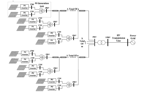 Figure 1: Configuration of a DPVP plant.
In view of the intermittent nature of the DPVP plant and the switching action of inverters, in case the harmonic current output of an individual PV generation inverter scheme is minimal, the output harmonic current of the cluster of PV generation inverter schemes has the potential to exceed the limitations recommended by the standard [9].
In [10], transformer losses that occur when facilitating solar PV farm environment were investigated based on seasons. The study in particular draw attention to the injection of harmonics and distortion using the IEEE Std. C57.110-2018 recommended practice. This work, an extension of the previous work in [10], examines the influence of harmonics and distortion on transformers during their service lifetime. The work further review the de-rating procedure recommended by IEEE for transformers under harmonic conditions. The work then proposes a novel procedure for de-rating transformers using the computational power of FEM. The proposed procedure takes into account of parameters suchlike skin effect, proximity effect, and the magnetic flux leakage that the analytical method (AM) recommended by the IEEE fails to take into consideration.
2. Effect of harmonic currents
During service the total transformer losses ( are comprised of the no-load loss ( and the load losses ( as expressed in eq. (1) below.
![]() The service no-load losses are as a result of the core excitation when the transformer is connected to the supply voltage and is independent of the loading profile. Under harmonic conditions, the harmonic current passing through resistance and leakage reactance of the transformer may deform the output voltage. Practical experience has demonstrated that the rise in temperature in the core is not a factor limiting the evaluation of the permissible current under harmonic conditions. Evidently, the C57.110-2018 [11] recommended practice for establishing transformer capability under harmonic conditions does not take the account the no-load losses under such conditions.
The service no-load losses are as a result of the core excitation when the transformer is connected to the supply voltage and is independent of the loading profile. Under harmonic conditions, the harmonic current passing through resistance and leakage reactance of the transformer may deform the output voltage. Practical experience has demonstrated that the rise in temperature in the core is not a factor limiting the evaluation of the permissible current under harmonic conditions. Evidently, the C57.110-2018 [11] recommended practice for establishing transformer capability under harmonic conditions does not take the account the no-load losses under such conditions.
The load losses ( ) are comprised of the copper losses ( and the winding stray losses in which are constituted by the winding Eddy losses ( and stray loss in structural parts ( as expressed in eq. (2) below [11].
![]() The copper losses signifies the heat dissipated by the load current in the transformer winding conductors. Under harmonic conditions if the load current increases, then the copper losses will also experience an increase. During the factory acceptance testing of a transformer there is no methodology available for the testing of the winding stray losses. Although, the impedance test can be employed to ascertain the total transformer losses. Then the winding stray losses can be acquired by deducting the copper losses from total transformer losses. In the event that the rated winding Eddy loss of a transformer is known, then this loss under harmonic conditions can be evaluated as expressed in in eq. (3) [11].
The copper losses signifies the heat dissipated by the load current in the transformer winding conductors. Under harmonic conditions if the load current increases, then the copper losses will also experience an increase. During the factory acceptance testing of a transformer there is no methodology available for the testing of the winding stray losses. Although, the impedance test can be employed to ascertain the total transformer losses. Then the winding stray losses can be acquired by deducting the copper losses from total transformer losses. In the event that the rated winding Eddy loss of a transformer is known, then this loss under harmonic conditions can be evaluated as expressed in in eq. (3) [11].
![]() The stray loss in structural parts can be evaluated for harmonic conditions by applying a similar procedure. In the 4th edition of the UL 1561 standard published in 2011[12], the Factor-K for de-rating a transformer is specified as expressed in eq. (4) below.
The stray loss in structural parts can be evaluated for harmonic conditions by applying a similar procedure. In the 4th edition of the UL 1561 standard published in 2011[12], the Factor-K for de-rating a transformer is specified as expressed in eq. (4) below.
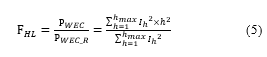
![]() The Factor-K indicates the effect of harmonic conditions upon the increase in the winding Eddy losses of the transformer. In the C57.110-2018 standard [11], the harmonic loss factor to account for the increase in the winding Eddy losses is expressed as follows in eq. (5).
The Factor-K indicates the effect of harmonic conditions upon the increase in the winding Eddy losses of the transformer. In the C57.110-2018 standard [11], the harmonic loss factor to account for the increase in the winding Eddy losses is expressed as follows in eq. (5).
 On the empirical studies conducted in [13], for evaluating the winding Eddy losses, eq. (6) and eq. (7) are established.
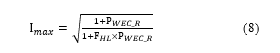
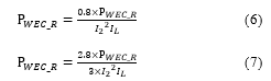 The maximum allowable harmonic load current formula recommended by the C57.110-2018 standard [11] of a transformer is the current whereupon the maximum winding Eddy loss ratio as expressed in eq. (8) below.
 3. Case scenario
In this case scenario, the technical characteristics of the studied 500kVA, three-phase, oil-immersed, DPVP transformer are presented in Table 1. The objective herein is to investigate the operational performance of the studied transformer that facilitate a harmonically distorted load current during service.
Table 1: Technical specification
| Item | Value |
| kVA rating | 500kVA |
| HV Voltage/HV Current | 11kV/1.44A |
| LV Voltage/LV Current | 400V/79.2A |
| Load Losses (@75% loading) | 1375W |
| HV winding resistance | 121.5 ohms |
| LC winding resistance | 0.03 ohms |
The corresponding harmonic load current considered in the analysis is presented in Figure 2. Further, the de-rating information of the studied transformer according to the analytical method and the proposed FEM procedure will be computed based upon the supplied harmonic load current.
In preparation to shed light on the concept of skin effect on the winding conductors at the fundamental frequency and under harmonic conditions, the two simulations with a round cross-section were investigated. These simulations substantiate the behaviour of the load current due to the applied frequency. At fundamental frequency, the effect of the skin effect upon the winding conductors will be as presented in Figure 3.
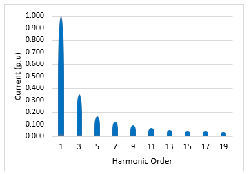 Figure 2: Harmonic spectrum.
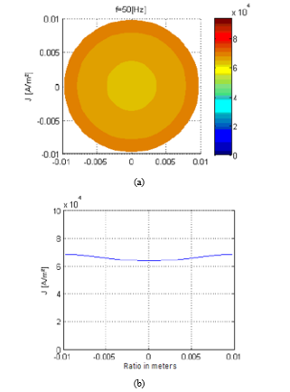 Figure 3: Winding conductor’s skin effect at a fundamental frequency
As anticipated, Figure 3 (a) illustrate a uniform dispersion through the winding conductor. The graphical representation of this effect is shown in Figure 3 (b). The 5th order of the supplied harmonic profile was investigated and the corresponding results in Fig. 4 demonstrate a concentration of the current upon the surface of the winding conductor as demonstrated by Figure 4(a). The graphical representation of this effect is also presented in Figure 4 (b).
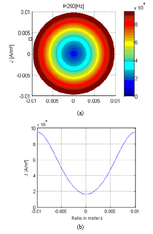 Figure 4: Winding conductor’s skin effect at 5th harmonic order
4. Results
In this section, the results for de-rating a transformer to facilitate the supplied harmonic load current using the analytical method and the proposed 3D FEM procedure.
4.1. Classical Approach: Analytical method
The winding Eddy losses at fundamental and under harmonic conditions are acquired by the difference between the total transformer losses and copper losses as:
The peak ratio of the winding Eddy losses is evaluated in p.u using eq. (6) given that the studied unit is within the category up to 650kVA.
In order to attain the Factor- K, the supplied harmonic load current is applied, as shown in Table 2.
Table 2: K-factor estimation
| h | (A) | (A) | (A) | |
| 1 | 1,000 | 1,000 | 1,000 | 1,000 |
| 3 | 0,350 | 0,123 | 9,000 | 1,103 |
| 5 | 0,170 | 0,029 | 25,000 | 0,723 |
| 7 | 0,120 | 0,014 | 49,000 | 0,706 |
| 9 | 0,092 | 0,008 | 81,000 | 0,686 |
| 11 | 0,071 | 0,005 | 121,000 | 0,610 |
| 13 | 0,051 | 0,003 | 169,000 | 0,440 |
| 15 | 0,043 | 0,002 | 225,000 | 0,416 |
| 17 | 0,040 | 0,002 | 289,000 | 0,462 |
| 19 | 0,039 | 0,002 | 324,000 | 0,493 |
| Ʃ | 1,187 | 6,637 |
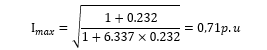
The maximum allowable current of the studied transformer based in eq. (8) is evaluated as follows:
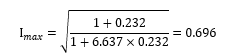 The maximum allowable load current in Ampere (A) is evaluated as:
![]() The continuous kVA rating of the transformer during service is evaluated as:
The continuous kVA rating of the transformer during service is evaluated as:
![]() During service, this equivalent kVA is the valuation of the continuous power rating the transformer will be operating on under the supplied harmonic spectrum. In the event the utility owner changes the harmonic loading seen by the transformer, the kVA must be re-evaluated
During service, this equivalent kVA is the valuation of the continuous power rating the transformer will be operating on under the supplied harmonic spectrum. In the event the utility owner changes the harmonic loading seen by the transformer, the kVA must be re-evaluated
4.2. Finite Element Method: Proposed Procedure
In the development of the proposed procedure, Ansys Maxwell, an electromagnetic field simulation software, is employed. A 3D cross-section of the three-phase, oil-immersed, DPVP transformer is developed for the finite element software. The short circuit test of the transformer is evaluated using the circuit model at fundamental and under harmonic conditions. The superposition property of the winding Eddy losses is employed in the event when the winding conductor dimensions are not more than the skin and proximity effect as well as when the flux degree is lesser than the saturation level. At large, the superposition property is employed to evaluate the transformer load losses under harmonic conditions. This loss is thereby the arithmetic sum of the losses due to different harmonic load current and harmonic orders. For the proposed FEM procedure, the windings’ leakage flux and resistance are used to calculate the different loss components.
In Figure 5, the 3D FEM cross-section of the studied transformer is presented. The model takes into account the actual geometries, material properties and the supplied harmonic spectrum. Undoubtedly, the finer meshing of the geometries takes an extended processing time but leads to the most optimised solution. Consequently, in the assessment of the various harmonic orders, a concession has been formed between the optimised solution and extended processing time.
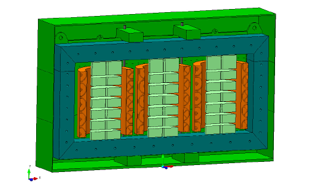 Figure 5: Proposed 2D FEM model
For the purpose of obtaining the results of the proposed 3D FEM procedure, the following steps are carried out on the transformer model:
- Excitation of the windings by the harmonic load current of each harmonic order,
- The corresponding flux density distribution in the active components are then calculated,
- The triggered currents generated by the distributed flux along with the material core, are determined, and
- The resistances of the windings are then presented to the geometries and the winding Eddy losses are then computed premised on the copper.
In the event the transformer under study is operating at a fundamental frequency, the load losses by employing the proposed FEM procedure are tabulated as shown in Table 3.
Table 3: Technical specification
| Loss component | Value |
| HV load loss (Watts) | 879,16 |
| LV Load loss (Watts) | 455,45 |
| Total Load loss (Watts) | 1334,59 |
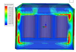 Figure 6: Magnetic flux leakage distribution.
In the magnetic circuit of the studied transformer, the distribution of the magnetic flux density is illustrated in Figure 6. At loading condition during service, the short circuit phenomena of the transformer may be presumed and the amplitude of the magnetisation current and leakage flux are minimal. As a result of the short circuit of the winding phases, significant density seeps through the windings. The latter presents a crucial factor in this condition. Under the supplied harmonic spectrum supplied in Figure 2, the total transformer losses are calculated as illustrated in Table 4 below.
The services load losses for each harmonic order is attained and tabulated as shown in Table 4 as 1410.53W.
Table 4: K-factor estimation
| h | (A) | (W) | (W) | (W) |
| 1 | 1,000 | 668,09 | 346,10 | 1014,19 |
| 3 | 0,350 | 167,02 | 86,53 | 253,55 |
| 5 | 0,170 | 58,28 | 29,68 | 87,95 |
| 7 | 0,120 | 20,05 | 11,49 | 31,54 |
| 9 | 0,092 | 6,68 | 2,87 | 9,56 |
| 11 | 0,071 | 5,51 | 2,83 | 8,34 |
| 13 | 0,051 | 1,82 | 0,74 | 2,56 |
| 15 | 0,043 | 0,61 | 0,49 | 1,10 |
| 17 | 0,040 | 0,81 | 0,39 | 1,20 |
| 19 | 0,039 | 0,37 | 0,18 | 0,55 |
| Ʃ | 929,24 | 481,29 | 1410,53 |
The winding Eddy losses at fundamental and under harmonic conditions are acquired by the difference between the total transformer losses and copper losses. The overall load current is at both conditions is presumed to be 1 p.u. The winding copper losses at a fundamental frequency and current as evaluated as:
![]() The winding Eddy losses at fundamental frequency are evaluated as:
The winding Eddy losses at fundamental frequency are evaluated as:
![]() The winding Eddy losses under harmonic conditions is evaluated as:
The winding Eddy losses under harmonic conditions is evaluated as:
![]() By employing eq. (5), the harmonic loss factor is the ratio of the winding Eddy losses under harmonic conditions and at fundamental frequency.
By employing eq. (5), the harmonic loss factor is the ratio of the winding Eddy losses under harmonic conditions and at fundamental frequency.
![]() Given that harmonic load current is equivalent to the rated current of the studied transformer (i.e. 1 p.u), the harmonic factor for the proposed FEM procedure is equal to the K-Factor as 6.337.
Given that harmonic load current is equivalent to the rated current of the studied transformer (i.e. 1 p.u), the harmonic factor for the proposed FEM procedure is equal to the K-Factor as 6.337.
4.3. Method Comparison
The most significant outcomes of de-rating the transformer under study are presented in this sub-section. To critically evaluate the performance of the analytical method and the proposed FEM procedure, the harmonic loss factors under the supplied harmonic spectrum are compared.
Table 5: Harmonic loss factor comparison
| Method | |
| AM | 6,693 |
| PFEM | 6,337 |
Comparatively, the proposed 3D FEM procedure envisage a lower harmonic loss factor than the analytical method as evidenced in Table 5. The assumption by the analytical method on the direct proportion between the winding Eddy losses and the harmonic load current is glitch, which then yield hidebound results. The maximum allowable current of the studied transformer based in eq. (8) is evaluated as follows:
 The maximum allowable load current in Ampere (A) is evaluated as:
![]() The equivalent power rating (in kVA) of the transformer using the proposed FEM procedure is:
The equivalent power rating (in kVA) of the transformer using the proposed FEM procedure is:
![]() The performance of the analytical procedure recommended by the C57.110-2018 standard and the proposed 3D FEM procedure are compare and tabulated as shown in Table 6. Comparatively, the results indicate that the two methods are close, regardless of the fact that the classical analytical procedure is hidebound.
The performance of the analytical procedure recommended by the C57.110-2018 standard and the proposed 3D FEM procedure are compare and tabulated as shown in Table 6. Comparatively, the results indicate that the two methods are close, regardless of the fact that the classical analytical procedure is hidebound.
Table 6: Transformer rating comparison
| Method | kVA | (A) |
| AM | 347,26 | 55,01 |
| PFEM | 353,10 | 55,93 |
A further look into the results indicates that since the analytical method cannot consider parameters such as skin effect, proximity effect, and the magnetic flux leakage on the windings, it can underestimate the equivalent kVA and maximum allowable current. Based on practical perspective during service, this unit may experience issues such as stray gassing. The authors presented the work related to this phenomenon in the publications [14] and [15]. The embedding of FEM into the design philosophy proves to have enhanced results. The authors herein have also presented additional work on this application in [16] and [17].
5. Conclusion
In this work, an extension of previous work [10], the impact of harmonics and distortion upon a DPVP transformer predicated on the classical method has been investigated with the ambition to examine its de-rating capability. A 3D FEM procedure has been proposed to evaluate the equivalent power rating and maximum allowable load current of a 500kVA, three-phase, oil-immersed, DPVP transformer. The following conclusions can be drawn from the case scenario and the practical experience of the transformer under study:
- The most crucial impact of the harmonics load current upon transformers planned for the DPVP application is the service winding Eddy losses and the load losses.
- A surge in the transformer service losses under harmonic conditions carries off premature insulation materials and designed transformer service lifetime. The power rating (kVA) of a DPVP transformer must consequently be de-rated under harmonic conditions.
- The conservative assumption of the C57.110-2018 standard of the direct proportion between the winding Eddy losses and the harmonic load current is a glitch as it does not take into account parameters suchlike skin effect, proximity effect, and the magnetic flux leakage on the windings
The proposed 3D FEM procedure as a highly accurate procedure for evaluating the transformer service losses under harmonic conditions as it takes into account parameters that cannot be captured by the procedure proposed by the C57.110-2018 standard may be employed in the final design stage for de-rating.
Conflict of Interest
The authors declare no conflict of interest.
- E. Cazacu, L. Petrescu and V. Ionita, “Derating of power distribution transformers serving nonlinear industrial loads,” in 2017 International Conference on Optimization of Electrical and Electronic Equipment (OPTIM) & 2017 Intl Aegean Conference on Electrical Machines and Power Electronics (ACEMP), Brasov, 90-95, 2017, doi: 10.1109/OPTIM.2017.7974953.
- D. Yildirim and E. F. Fuchs, “Measured transformer derating and comparison with harmonic loss factor (F/sub HL/) approach,” in IEEE Transactions on Power Delivery, 15 (1), 186-191, 2000, doi: 10.1109/61.847249.
- E. Cherian and G. R. Bindu, “Minimizing Harmonics and Transformer Derating in Low Voltage Distribution Networks by DC Distribution,” in 2018 International Conference on Emerging Trends and Innovations In Engineering And Technological Research (ICETIETR), Ernakulam, 2018, 1-6, doi: 10.1109/ICETIETR.2018.8529063.
- B. P. Das and Z. Radakovic, “Is Transformer kVA Derating Always Required Under Harmonics? A Manufacturer’s Perspective,” in IEEE Transactions on Power Delivery, 33 (6), 2693-2699, 2018, doi: 10.1109/TPWRD.2018.2815901.
- D. W. Egolf and A. J. Flechsig, “Harmonics-transformer derating,” in Proceedings of Industrial and Commercial Power Systems Conference, Irvine, CA, USA, 79-84, 1994, doi: 10.1109/ICPS.1994.303557.
- E. Cazacu and L. Petrescu, “On-site derating of in-service power distribution transformers supplying nolinear loads“, Revue Roumaine des Sciences Techniques – Serie Électrotechnique et Énergétique 59(3), 259-268, 2014, doi: 18845326 .
- A.Y Shklyarskiy and A I Bardanov , “Test of the method for calculation of derating of workshop transformers on engineering plants”, IOP Conf. Series: Materials Science and Engineering, 177, 012054, 2017, doi:10.1088/1757-899X/177/1/012054.
- N. Xie, A. Luo, Fujun Ma, et al., “Harmonic interaction between large-scale photovoltaic power stations and grid”, Proceedings of the Chinese Society of Electrical Engineering, 33(34), 9-16, 2013, doi: 288752772.
- IEEE Recommended Practices and Requirements for Harmonic Control in Electrical Power Systems,” in IEEE Std 519-1992 ,1-112, 1993, doi: 10.1109/IEEESTD.1993.114370.
- B. A. Thango, J. A. Jordaan and A. F. Nnachi, “Contemplation of Harmonic Currents Loading on Large-Scale Photovoltaic Transformers,” in 2020 6th IEEE International Energy Conference (ENERGYCon), Gammarth, Tunis, Tunisia, 2020, 479-483, doi: 10.1109/ENERGYCon48941.2020.9236514.
- IEEE Recommended Practice for Establishing Liquid-Immersed and Dry-Type Power and Distribution Transformer Capability When Supplying Nonsinusoidal Load Currents,” in IEEE Std C57.110™-2018 (Revision of IEEE Std C57.110-2008), 1-68, 2018, doi: 10.1109/IEEESTD.2018.8511103.
- UL 1561, UL Standard for Safety Dry-Type General Purpose and Power Transformer, 4th Edition, 2011, doi: 00096942.
- J. Faiz, M.B.B Sharifian, S.A. Fakheri , “Research report on effect of non-linear loads upon distribution transformers and correction factor estimation for optimal operation of transformer-Part I”, (in Persian), Azarbaijan Regional Electricity Company, Tabriz, Iran, 2001.
- D.B. Nyandeni, M. Phoshoko (Pr. Eng.), R. Murray, B.A. Thango, “Transformer Oil Degradation on PV Plants – A Case Study”, 8th South Africa regional conference, 14-17, 2017, doi: 10.1109/MEI.2014.6749569.
- B. A. Thango, Jacobus A. Jordaan and Agha F. Nnachi, “Stray Gassing of Transformer Oil in Distributed Solar Photovoltaic (DSPV) Systems” 6th IEEE R8 International ENERGY Conference, 13-16, 2020, doi: 10.1109/ENERGYCon48941.2020.9236522.
- B.A Thango, J.A Jordaan, A.F Nnachi, D.B Nyandeni “Solar Power Plant Transformer Loss Calculation under Harmonic Currents using Field Element Method”, 9th CIGRE Southern Africa Regional Conference, 1st – 4th October 2019, doi: 10.1109/MEI.2014.6749569.
- B. A. Thango, J.A. Jordaan, A. F. Nnachi, “Step-Up Transformers for PV Plants: Load Loss Estimation under Harmonic Conditions”, 19th International Conference on Harmonics and Quality of Power (ICHQP), 2020, doi: 10.1109/ICHQP46026.2020.9177938.