Performance of Vertical Axis Wind Turbine Type of Slant Straight Blades

Adv. Sci. Technol. Eng. Syst. J. 6(4), 292–297 (2021);
 DOI: 10.25046/aj060432
There is no doubt that energy is one of the most important requirements of life, and its importance increases with the passage of time, and this is what make countries to harness the capabilities and scientists in developing energy systems of all kinds, one of the most important energy systems these days is what is known as vertical axis wind turbines. If we compare this type of system with horizontal axis wind turbines, it is characterized by a relatively lower manufacturing cost. But on the other hand, it suffers from less efficiency in addition to the problem of starting the self-movement. The idea of this research revolves around the use of an engineering design for the vertical axis wind rotor that is very rarely used in the field of wind energy. This design takes the geometric shape of two inverted trapezoids. Within the framework of this study, the term “slant straight-blade vertical axis wind turbine” (SS-VAWT) was assigned to the wind rotor. Amendments have been made to the mathematical model of Multi stream tube to make it suitable for application and work on (SS-VAWT), where, it is known that the multi-stream tube model uses primarily and only for the original Darrieus and the H-Darrieus rotors. In order to prove the efficacy of the software used, the results obtained from it were compared with the practical results of previous studies, as it proved its effectiveness in obtaining the satisfactory results that were intended for this analysis. The analyzes and investigations that were conducted on the improved SS design included changing the geometry by changing some of its dimensional parameters represented in rotor height, rotor diameter, number of rotor blades, rotor blade section length, rotor blade section type and rotor blades inclination angle on the horizontal plane. Within the scope of the case studies that were worked on in this research, the results showed that the best efficiency of the SS rotor was achieved in the range of height to radius ratio (0.66 to 1), cord line length to radius ratio about 0.12 The angle of inclination of the blades is between 45- and 65-degrees Degree. In these ranges, the value of Max power factors has reached its turn, and the energetic range of the rotor has increased as a function of the peripheral relative velocity, in addition to a relatively large solution to the problem of starting self-movement, which appears through the highest-power factor values to move away from the limits of negative values in the range Terminal forgetfulness from 1 to 3. In addition, the effect of changing Raynaud’s number on the turbine aerodynamic performance has been investigated. The results showed that the higher the Reynolds value, the higher the power factor value, the higher the energy range and the lessening the problem of starting the self-movement.
1. Introduction
This paper is an extension work originally presented in “2020 IEEE International Conference on Environment and Electrical Engineering and 2020 IEEE Industrial and Commercial Power Systems Europe (EEEIC / I&CPS Europe)” [1]. Due to the increase in the costs of electric energy consumption with the progression of time, we have called for the need to focus on renewable energies and invest them in order to meet the needs of humanity in terms of energy, because of the advantages of renewable energies such as their presence in nature permanently, inexhaustible, clean, multi-source and free of charge in nature. Where you need systems to harness and convert it into electrical energy. The most important types of wind energy and solar energy. [2], [3]. When the wind passes according to the “cut in speed Vc” of the vertical axis wind rotor, the air rotor acquires a rotational speed around the rotor shaft to make q angle from 00 to 3600, and thus the ends of the rotor blades acquire a continuous terminal speed in wr, which there is a difference in the values and proportionality between the wind speed V in contact with the rotor, this leads to the formation of what is known relative velocity W, which make the angle of attack a with the direction of the wr, therefore there is a strong relationship between the angle of attack a and the Tip Speed Ratio l0 or (wR/V1). In the science of aerodynamics, specifically in the field of wings and blades, it is known that the angle of attack a has a direct and strong effect on the forces of lift L and Drag D, meaning that it has an effect on the ratio (L/D). Accordingly, the link between the terminal relative velocity and the ratio (L/D) becomes clear. Linking to the above, in order to achieve optimal efficiency to the rotor, must be sure, that the values of each wR/V1, a, q and L/D are consistent [4]-[7]. With the aim of developing the efficiency of VAWT’s, many different engineering designs have emerged that compete with each other in terms of high performance and lower manufacturing cost [8]-[12]. Following some instances from VAWT’s engineering designs. Original Darrieus-VAWT, its engineering shape is a parabolic, it gains its rotational movement from the lift force generated on its blades as a result of aerodynamics. On the other hand, this system suffers from a low coefficient of performance Cp, which does not exceed 35%. It also vibrates severely when rotating, which makes its manufacturing cost high due to the increase in structural supports to reduce vibrations [13]-[16]. Darrieus was developed so that his rotary shape became in the form of H, so it was called H-Darrieus, The H-Darrieus is nearly as efficient as the original Darrieus, but has lower manufacturing costs due to its straight blades [17]-[21]. The Helical-turbine is one of the most important developments of vertical axis wind turbines. It is characterized by its aerodynamic equilibrium during its rotation, as well as overcoming structural problems such as bending stress and vibrations. While its efficiency is slightly lower than other types. [22], [23]. All types of vertical axis air fans that were mentioned above and that were not mentioned also, suffer from the inability of the air rotor to start rotating. This problem is relatively addressed by adding a secondary system that relies in its rotation on obstruction to make the air rotor easier to start rotating. But this solution did not completely solve the self-starting problem [24]-[27]. All VAWT’s models of vertical axis wind turbines were produced and attempted to be sold globally as HAWT’s, but with little traction [28], [29]. The originality of this research appears in its geometric design, which takes the form of two inverted parabolas, and the modification of the famous mathematical method “Multi-Stream Tubes” MST so that it becomes appropriate to apply it to this design. The objective of this improved design is to increase the power factor and reduce the problem of starting movement compared to other types of VAWT’s. Figure 1 illustrates the developed design of this research. The work methodology was completed so that twelve geometric shapes of the rotor SS-VAWT were selected, different among them in terms of rotor height 2H, rotor diameter 2R, number of rotor blades N, length of rotor blade cross section C or rotor blade inclination angle b. Subsequently, several analyzes were conducted with the aim of verifying the effect of SS-VAWT rotor geometry variables on its performance. Through the results of the analyses conducted by a software specially designed for this research, the optimum engineering design of the SS-VAWT rotor was reached, which was moved to other stages of this research, including analyzes by Ansys Fluent, manufacturing a prototype and testing it in a wind tunnel. This is a comprehensive research that started with a developed idea that came based on an extensive review of many previous studies and research, this paper shows theoretical aspects that have an applied research extension that is being implemented now through the manufacturing processes of a prototype which will be shown by the experiments that will be conducted on it in subsequent papers in the future.
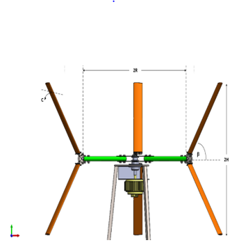 Figure 1: Geometry shape of SS-VAWT model by Solidworks
2. Method
The Multi-Stream Tube is mathematical method used in this work with certain adjustments to be optimal for apply to SS-VAWT and this model is preferred because it has a strong predictability for overall power production of the rotor and is also distinguished by efficiency and ease of use in the study of the influence of geometrical shape parameters on performance of wind rotor. With relation to details provided in [30], a brief overview of this model is offered. The rotor is substituted by the named “imaginary actuator disk.” This disk was blocked by a sequence of “stream-tubes.” It is an imagined tubs, the top of which consists of a stream-line, and thus the velocity vector is tangent everywhere on its surface. The velocity of the air across the disk differs from one stream-tube to another, much as the velocity of the air during the stream-tube shifts from its “free velocity” value V1 in front of the disk to its air velocity value “V” at the disk stage and even to its velocity “V2” at the wake area behind the disk. This continuous variation in disk velocity happens when part of the kinetic energy in the flow from which it passes is extracted [31]. Previous experimental data obtained in a wind tunnel was used to evaluate the software. The program was created to evaluate three different kinds of vertical axis wind turbines: original Darrieus rotor (Darrieus-VAWT), straight blades Darrieus rotor (H-VAWT), and slant straight blades rotor (SS-VAWT), the latter of which is the subject of this study. Figure 2 depicts the program approach in detail. Table 1 lists the twelve different SS-VAWT designs that have been examined and their efficiency characteristics evaluated. The aerodynamic efficiency under the control of geometrical variables like blade inclination angle (b), wind rotor height (2H), wind rotor diameter (2R), number of rotor blades (N), and airfoil chord line was expressed using power factor curves derived from the analysis phase of the twelve configurations (C). For the presentation of the results in the shape of the Cp curves, the data for the rotor output are typically shown in non-dimensional formats, which allows such data to be utilized irrespective of the wind rotor scale while preserving geometric continuity across rotors in various dimensions. As a result, power coefficient curves as a characteristic of tip speed ratio are popular. The following diagram depicts the presentation of many important equations in the utilized model.
Table 1: Twelve configurations of SS-VAWT
| “H” change configurations | ||||||
| N | R | H | C | |||
| 3 | 1 | 0.5 | 0.12 | |||
| 3 | 1 | 1 | 0.12 | |||
| 3 | 1 | 1.5 | 0.12 | |||
| “R” change configurations | ||||||
| N | R | H | C | |||
| 3 | 0.5 | 1 | 0.12 | |||
| 3 | 1 | 1 | 0.12 | |||
| 3 | 1.5 | 1 | 0.12 | |||
| “N” change configurations | ||||||
| N | R | H | C | |||
| 2 | 1 | 1 | 0.12 | |||
| 3 | 1 | 1 | 0.12 | |||
| 4 | 1 | 1 | 0.12 | |||
| “C” change configurations | ||||||
| N | R | H | C | |||
| 3 | 1 | 1 | 0.06 | |||
| 3 | 1 | 1 | 0.12 | |||
| 3 | 1 | 1 | 0.18 | |||
2.1. Mathematical Expressions
- following SS-VAWT geometry expression was created for this research:
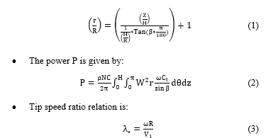
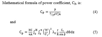
 Figure 2: Flowchart of the software utilized
3. Results and Discussion
3.1. (b) Effect at Variable Values of H
The design group specialized in studying the effect of H change with b change is shown in Figure 3. The results are divided into four classes of curves, each group representing a different b angle, where we have four different angles as discussed above. In the same way, each category contains three curves that resulted from three different H values. The influence of the b angle on the Cp at three different values of H can be expressed as follows: at an angle of 85 degrees, the curves pattern did not vary much and there was a severe convergence between them, suggesting that there is no major effect of H value difference at this angle. The rotation began with a value of The value of CpM approached 0.3 at a value of l0 of around 3.8, and the values of the power factor appeared in a small l0 range between 3 and 5, indicating that the turbine is inefficient in this case due to the low value of CpM, the narrow range of l0, and the magnitude of the self-starting issue. When b is equivalent to 65, the turbine’s output increases when opposed to the situation where the angle is 85 degrees. In this scenario, the original l0 value is between 2 and 2.6, and the CpM at a comparable l0 value of 3.2 is calculated to be about 0.36. Furthermore, the value of l0 has improved, now varying between 2.2 and 4.8. As a consequence, these circumstances culminated in a relative dominance of 85 over the b. In comparison to the previous two cases of b equal to 85 and 65 degrees, the efficiency excellence of the third party described by b equal to 45 degrees is apparent. As the turbine rotation range increased from l0 (approximately 1.2) to l (approximately 4 and 5), the turbine rotation range also grew. Furthermore, the CpM values have been improved to approximately 0.36 and 0.42. To be more precise, the wind turbine in this case offered more control, a longer operating range, and a solution to the self-starting dilemma. When the b is equivalent to 25 degrees, the output of the SS-VAWT is investigated, the curves reveal that the turbine works poorly and is unsuitable for electrical energy generation. Where the power factor CpM highest value varied from 0.16 to 0.27.
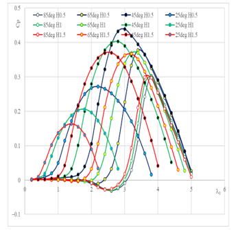 Figure 3: Power factor curves for twelve geometric shapes with change in height and angle of inclination of the blades.
3.2. (b) Effect at variable values of R
As seen in Figure 4 changing the angle and rotor radius values results in different Cp curve action. The engineering configurations that performed best were (b = 85, R = 1.5), (b = 65, R = 1.5, 1), and (b = 45, R = 1.5, 1), with CpM values ranging from 0.36 to 0.45. However, in terms of the energy continuum, (b = 65 degrees, R =1.5) and (b = 45 degrees, R =1.5) is preferred, with the rotor (b= 45 degrees, R =1.5) marked by an early start of rotational speed at the value of = 1.6. The bulk of the instances in Figure 4 had a relatively narrow energy range and a very low Cp, which led to poor performance.
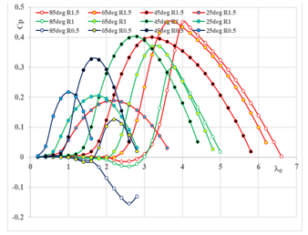 Figure 4: Power factor curves for twelve geometric shapes with change in diameter and angle of inclination of the blades.
3.3. (b) Effect at variable values of N
The three classes of curves in Figure 5 each show a specified N as 2, 3, or 4 and each include four curve angles = 85, 65, 45, and 25 degrees. It’s readily evident in each category where N remains unaltered that the value of CpM increases, then falls, with the peak of CpM occurring at angles of 65 and 45 degrees. If we define the curves in another way, dividing them into four classes, each with a different fixed angle and vector N, we can see that when the beta 85 decreases dramatically, the value of the CpM decreases sharply as well, and the value of the energy spectrum decreases as well. It is obvious that modifying the conduct of curves at = 65 degrees is equivalent to changing attitudes at = 85 degrees in the preceding example. In the case of = 45 degrees, changing the value of N has no effect on the value of CpM, where It ranged between 0.37 and 0.40 in both situations, and it is balanced by values varying between 2.4 and 3, and the energy spectrum seems broad as compared to other sample cases. Finally, in the case of 25, the value of CpM rises with increasing N, but it does not surpass 0.24, considering the fact that the energy spectrum stays very small despite the shift in N.
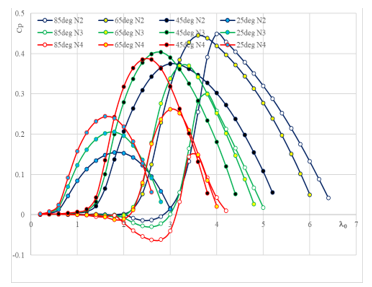 Figure 5: Power factor curves for twelve geometric shapes with change in number of blades and angle of inclination of the blades.
3.4. (b) Effect at variable values of C
Figure 6 expresses the effect of changing the blade section length on the SS-VAWT rotor in terms of power factor curves patterns. It is clear that there is a great similarity in the patterns of the Figure 6 curves with the patterns of the Figure 5 curves in paragraph 3.3. Thus, the ratio N/C can be used instead of N separately and C separately to check the efficiency of the SS-VAWT as a shortening of the analysis time.
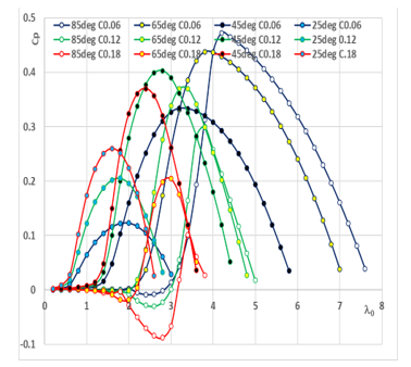 Figure 6: Power factor curves for twelve geometric shapes with change in cord line length and angle of inclination of the blades
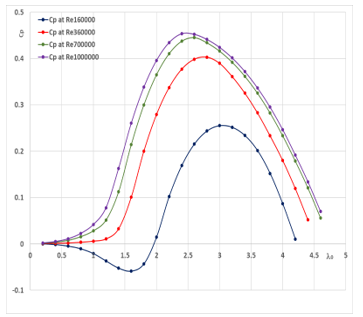 Figure 7: Influence of Reynolds Number on performance of SS-VAWT
3.5. Effect Reynolds Number on power factor of SS-VAWT
Figure 7. shows the change in the power factor values by changing the Reynolds number values. The values are 160000, 360000, 700000 and 1000000 [32]. It can be seen that in the case Reynolds number is equal to 160,000 the value of CpM is 0.25 and corresponding to l0 equal to 3. When Reynolds number is equal to 360,000, the CpM value is 0.4 and corresponding to l0 is 2.8. As for the Reynolds number equal to 700000, the CpM value is 0.44 and occurred at l0 equals 2.6. Finally, the Reynold Number 1000000 yielded CpM is 0.46 corresponding to a l0 of 2.4 value. Power factor curves also show that the power range ranges from 2 to 4.2 when the Re is 160,000, and 1.7 – 4.4 for Re equal to 360,000, and when Re = 700,000 shows the power range from 1.4 to 4.6, while at Re =1000000 the power range is 1.2 -4.7.
4. Conclusion
Within the scope of this research, the computer program achieved its objectives, as it predicted with high accuracy the power factor of the SS-VAWT rotor in many different study cases. By comparing with a previous study case that was harnessed for comparison only, the program is in great agreement with the practical results. The most important results extracted from this research are that the highest CpM values and the widest energetic range are achieved at angles of inclination of the blades between 45° and 65°. Regarding the problem of initiation of movement of the rotor, the satisfactory results were in the research cases in which the angles of inclination of the blades are between 25° and 45°. Regarding the effect of the Reynolds number on the performance of the SS-VAWT rotor, when Re value increase, the CP values increase, and consequently the CpM values increase. Moreover, as the Re values rise, the power range rises over the l0 values. Also, the problem of the self-starting appeared to diminish as the Re values accented.
Conflict of Interest
The authors declare no conflict of interest.
- H. Abusannuga and M. Özkaymak, “Towards Evaluating the Performance of Vertical Axis Wind Turbine Consist of Slant Straight Blades,” in 2020 IEEE International Conference on Environment and Electrical Engineering and 2020 IEEE Industrial and Commercial Power Systems Europe (EEEIC / I&CPS Europe), Madrid, 2020.
- A. Kulshrestha, O. Mahela, M. Gupta, N. Gupta, N. Patel, T. Senjyu, M. Danish and M. Khosravy, “A Hybrid Fault Recognition Algorithm Using Stockwell Transform and Wigner Distribution Function for Power System Network with Solar Energy Penetration,” Energies, (13), 2020. https://doi.org/10.3390/en13143519.
- A. Faramarz, T. Shiro, N. Tsutomu, N. Tomokazu, M.R. Asharif, ” Analysis of Non-linear Adaptive Friction and Pitch Angle Control of Small-Scaled Wind Turbine System,” (eds) Control and Automation, and Energy System Engineering. Communications in Computer and Information Science, (256), 2011. https://doi.org/10.1007/978-3-642-26010-0_4
- B. F. Blackwell, “The Vertical-Axis Wind Turbine “How It Works”,” Sandia Laboratories, Albuquerque, New Mexico, 1974.
- R. Templin, “Aerodynamic Performance Theory for the NRC Vertical-Axis Wind Turbine,” National Aeronautical Establishment, LTR-LA-160, Canada, 1974.
- M.J. Ralph, S.V. Maria and D. J. Ray, “Theoretical Performance Of Cross-Wind Axis Turbines With Results For A Catenary Vertical Axis Configuration,” NASA Langley Research Center, Virginia, 1975.
- P. N. Shankar, “On The Aerodynamic Performance of a Class of Vertical Shaft Windmills,” Proceedings of the Royal Society of London. Series A, Mathematical and Physical Sciences, 349(1656), 35-51, 1976.
- E. Sheldahl, B.F. Blackwell, “Free-Air Performance Tests of a 5-Metre-Diameter Darrieus Turbine,” Sandia Laboratories, New Mexico, 1977.
- I.Paraschivoiu, “Double-Multiple Streamtube Model For Darrieus Wind Turbines,” in Institut de Recherche de l’Hydro-Quebec, Quebec, 1981.
- P.M. Kumar, K. Sivalingam, S. Narasimalu, T.C. Lim, S. Ramakrishna and H. Wei “A Review on the Evolution of Darrieus Vertical Axis Wind Turbine: Small Wind Turbines,” Journal of Power and Energy Engineering, (7), 27-44, 2019.
- B. Muhammad, H. Nasir, F. Ahmed, A. Zain, J. Sh. Rehan and H. Zahid, “Vertical Axis Wind Turbine – A Review of Various Configurations And Design Techniques,” Renewable and Sustainable Energy Reviews, 16(4), 1926-1939, 2012.
- T. Dang, “Introduction, History, And Theory of Wind Power,” in 41st North American Power Symposium, Starkville, MS, 2009.
- W. Tjiu, T. Marnoto, M. Sohif, H. Ruslan and K. Sopian, “Darrieus Vertical Axis Wind Turbine For Power Generation I: Assessment Of Darrieus VAWT Configurations,” Renewable Energy, (75), 50–67, 2015.
- A.D. Thomas, L.M. Timothy, “Developments in Blade Shape Design for a Darrieus Vertical Axis Wind Turbine,” Sandia National Laboratories, Albuquerque, New Mexico, 1986.
- K.G. Emil, “Characteristics of Future Vertical Axis Wind Turbines,” Sandia National Laboratories, Albuquerque, New Mexico, 1982.
- W. Tjiu, T. Marnoto, M. Sohif, H. Ruslan, K. Sopian, “Darrieus vertical axis wind turbine for power generation II: Challenges in HAWT and the opportunity of multi-megawatt Darrieus VAWT development,” Renewable Energy, (75), 560-571, 2015.
- W. S. Bannister, “Aerodynamic Studies Of A Straight-Bladed Vertical-Axis Wind Turbine,” in 1St. B.W.E.A Wind Energy Workshop, Springfield, VA, 1979.
- W. S. Bannister, “A Theoretical Analysis Of Small Vertical Axis Wind Turbines,” in International Synposium on “Applications of Fluid Mechanics and Heat Transfer to Energy and Environmental Problems, Greece, 1981.
- Y. Hara., N. Horita, S. Yoshida, H. Akimoto, T. Sumi, “Numerical Analysis of Effects of Arms with Different Cross-Sections on Straight-Bladed Vertical Axis Wind Turbine,” Energies, 12(11), 2019, https://doi.org/10.3390/en12112106
- J. Fadil, Soedibyo, M. Ashari, “Performance Analysis Of Vertical Axis Wind Turbine With Variable Swept Area,”, International Seminar on Intelligent Technology and Its Applications (ISITIA), Surabaya, 2017.
- A. Gorlov, “Development of the Helical Reaction Hydraulic Turbine,” Northeastern University, Boston, 1998.
- D. Han, Y. Heo, N. Choi, S. Nam, K. Choi, K. Kim, “Design, Fabrication, and Performance Test of a 100-W Helical-Blade Vertical-Axis Wind Turbine at Low Tip-Speed Ratio,” Energies, 11(6), 2018.
- M. Rahman, T. Salyers, , A. Mahbub, A. ElShahat, V. Soloiu, and M. Emile, “Investigation of Aerodynamic Performance of Helical Shape Vertical-Axis Wind Turbine Models With Various Number of Blades Using Wind Tunnel Testing and Computational Fluid Dynamics,”, International Mechanical Engineering Congress and Exposition, Phoenix, Arizona, 2016.
- R. Dominy, P. Lunt, A. Bickerdyke, J. Dominy, “Self-Starting Capability Of A Darrieus Turbine,” Journal of Power and Energy, 221(1), 111–120, 2007.
- J. Zhu, H. Huang, & H. Shen, “Self-Starting Aerodynamics Analysis Of Vertical Axis Wind Turbine,” Advances in Mechanical Engineering, 7(12), 2015.
- M.S. Omar, I.A. Ahmed, E.A. Ahmed, A.A. Amr, A. M. Elbaz, “Numerical Investigation Of Darrieus Wind Turbine With Slotted Airfoil Blades,” Energy Conversion and Management: X, 5, 100026, 2020.
- J. Krishnaraj, Sivakumar Ellappan, M. Anil Kumar, “Additive Manufacturing of a Gorlov Helical Type Vertical Axis Wind Turbine,” International Journal of Engineering and Advanced Technology (IJEAT), 9(2), 2019.
- IRENA, “Future of wind: Deployment, investment, technology, grid integration and socio-economic aspects,” International Renewable Energy Agency (IRENA), Abu Dhabi, 2019.
- J. Damota, I. Lamas, A. Couce, J. Rodríguez, “Vertical Axis Wind Turbines: Current Technologies and Future Trends,” in International Conference on Renewable Energies and Power Quality (ICREPQ’15), Coruna, 2015.
- H.J. Strickland, “The Darrieus Turbine: A Performance Prediction Model Using Multiple Streamtubes,” Sandia Laboratories, Albuquerque, New Mexico, 1975.
- N. Batista, R. Melício, V. Mendes, J. Figueiredo, A. Reis, “Darrieus Wind Turbine Performance Prediction: Computational Modeling,”, 4th Doctoral Conference on Computing, Electrical and Industrial, Costa de Caparica, 2013.
- R. E. Sheldahl, Klimas, P C, “Aerodynamic Characteristics of Seven Symmetrical Airfoil Sections Through 180-Degree Angle of Attack for Use in Aerodynamic Analysis of Vertical Axis Wind Turbines,” Sandia National Laboratories, United States, 1981.
No related articles were found.