Modelling and Simulation of Fuzzy-based Coordination of Trajectory Planning and Obstacle Avoiding for RRP-Typed SCARA Robots

Adv. Sci. Technol. Eng. Syst. J. 6(4), 348–354 (2021);
 DOI: 10.25046/aj060439
In this article, a fuzzy-based solution of coordination between behaviors of trajectory planning and obstacle avoiding in a RRP-typed SCARA robot control is presented. The first idea of the proposed solution is to divide a robot’s complex behavior into simpler parallel behaviors. The second key idea is a fuzzy-based coordination between these behaviors to make smooth robot motions without collision. The modelling and simulation on Matlab are executed to test the performance of the proposed solutions under basic circumstances.
1. Introduction
The Selective Compliance Assembly Robot Arm (SCARA robot) was firstly invented in 1978 [1]. Since then, SCARA robot has been developed for different Degree of Freedom (DoF) such as 3-DoF [2], [3], 4-DoF [4], 5-DoF [5,6], and 6-DoF [7], [8]. In particular, SCARA robot with 3-DoF has become one of the most applied industrial robots due to its simple and basic kinematic structures.
In the basic group of 3-DoF industrial robots, there are many different categories of kinematic structures including articulated manipulators [9], Spherical manipulators [10], SCARA manipulators [11], cylinder manipulators [12], cartesian manipulators [13]. Among these categories, RRP-typed SCARA robots have been strongly invested because of flexible trajectory planning solutions with rapidly exploring random algorithms.
Fuzzy logic is an intelligent control tool that simplifies the complexity of nonlinear control through IF-THEN rules. Thanks to this advantage, many fuzzy logic solutions are proposed for controlling 3-DoF SCARA robot such as trajectory tracking control [2], position control [14], path planning control [15], obstacle avoidance [16], [17]. The Matlab simulation results of [2] show that it is possible to apply fuzzy logic for the RRP-typed SCARA controller to reduce the loop trajectory errors. From the result in [14], it is proven that the designed fuzzy logic controller help the RRP SCARA robot move smoother for tracking trajectory but without obstacle avoidance. Similarly, the proposed design in [15] confirms that fuzzy logic application makes the RRP-typed SCARA robot movement faster than the conventional PD controller in path planning. Furthermore, [16] and [17] proposed fuzzy-based solutions for obstacle avoidance of the robotic manipulators. The simulation results demonstrate that fuzzy-based obstacle avoidance provides SCARA robots better solutions of local planning without any collisions. The computational complexity, however, increases due to the repeated use of the nonlinear functions of the fuzzy logic.
Different to the above-mentioned results, in [18] a fuzzy-based basic solution is proposed for coordinating obstacle avoidance and path planning behaviors of 6-DoF humanoid mobile robots. The main ideas of the solution is to divide a complex robot behavior into simpler behaviors and organize the behaviors in a hierarchical chart so that an upper class behavior consists of some behaviors in the lower class. The main ideas in [18] is reused in this research but for a 3-DoF robot to reduce the computational complexity of the robot control system. The proposed fuzzy-based coordination between parallel behaviors makes the robot movement smooth according to the changing obstacle distance. The article is presented as follows: First, the kinematic structure of RRP-typed SCARA robot is introduced. Then, a hierarchical chart of behaviors of trajectory planning and obstacle avoidance are analyzed. After that, a modular diagram of SCARA robot control system is given with the separable modules for trajectory planning and collision avoidance and fuzzy-based coordination. Finally, the Matlab simulations are analyzed to test the system performance.
2. Kinematics
2.1. Kinematic structure
The structure of RRP-typed SCARA robot with 3-DoF includes 2 revolute (R) (or rotating joints) and one prismatic (P) (or translating joint) as shown on the left side in Fig.1.
These joints are operated by 3 independent actuators to control the pose (including position and direction) of the End-Effector (E) following a desired trajectory.
The basic structure of RRT-typed SCARA robot consists of 4 parts: Base B0, revolute joint R1, revolute joint R2 and prismatic joint P3 as shown on the right side in Fig. 1.
The kinematic parameters in Fig. 2 are defined as follows:
+ d0 is the height from base B0 to joint R1 along Z0 axis;
+ a1 and a2 are the lengths of the arms 1 and 2 along axes X1 and X2, respectively;
+ θ1 and θ2 are the rotation angles of joints R1 and R2 around axes Z1 and Z2, respectively;
+ d3 is the distance from joint P3 to the end-effector E.
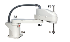 Figure 1: Basic structure of RRT-typed SCARA robot
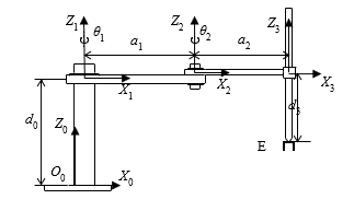 Figure 2: Kinematic structure of the SCARA robot
2.2. Homogeneous transformation
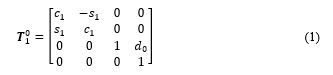
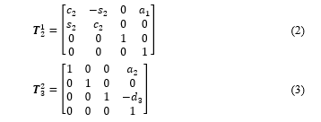
According to the Denavit-Hartenberg (D-H) of homogeneous transformation rules in [19], the D-H parameters of the SCARA robot can be setup in the table shown in Table 1. Using the D-H parameter table, the transformation matrices are as follows:
 where:
– , , are respectively matrices of homogeneous transformation between the coordinate systems from to , from to , and from to .
– , , , are respectively the symbols of , , , .
To calculate the homogeneous transformation matrix from the origin to the end-effector E, we perform the matrix multiplication as follows:
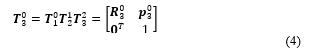 The detail computation of equation (4) is carried out as follows:
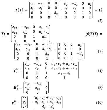 Table 1: Denavit-Hartenberg parameters of the SCARA robot
| Joint | ||||
| 1 | 0 | 0 | ||
| 2 | 0 | 0 | ||
| 3 | 0 | 0 | ||
| * means variable | ||||
where
– are transformation matrix, orientation matrix, and position matrix of the end-effector E in comparison with base B0.
– , notes for , , respectively.
– are respectively the coordinates of the end-effector E projected on the axes X, Y, Z of .
2.3. Inverse kinematic computation
According to [20], the inverse kinematics problem consists of the determination of the joint variables corresponding to a given end-effector position and orientation. The solution to this problem is of fundamental importance in order to transform the motion specifications, assigned to the end-effector in the operational space, in to the corresponding joint space motions that allow an execution of the desired motion.
In this study, the inverse kinematics problem requires to find out the 2 joint variables concerning angles and the displacement d3 based on the given pose of the end-effector E, that means and are known.
To solve this problem, the top-viewed projections of the SCARA robot, as shown in Figure 3, allows formula (10) to mathematically express in a different way as follows:
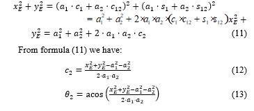
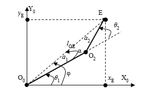 Figure 3: Top-viewed Projections on plane OXYZ0
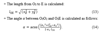
To calculate angle , the geometric calculation method can be used under the projections on the plane OXYZ0 as follows:
Let consider triangle O0O2E and use mathematic computations:
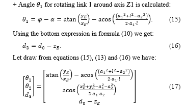 In summary, based on formula (17) it is possible to simulate RRT-typed SCARA robot movement by giving the coordinates of waypoints (or path points) to form a desired trajectory.
In the next section, the calculation based on these waypoints for planning trajectory is presented. After that, the calculation for avoiding obstacle is analyzed. Based on these calculations, both kinds of behaviors concerning planning trajectory and avoiding obstacle are organized in a hierarchical chart before applying fuzzy logic for coordinating them.
3. Planning trajectory and avoiding obstacle
3.1. Planning trajectory
According to [19], to reduce the complexity of motion control, a complex path can be replaced with a sequence of n waypoints to ensure motion along the desired trajectory .
To travel over all n waypoints at certain instants of time, it should be better to compute the actuating commands for tracking each segment of the desired trajectory between two adjacent waypoints by assigning the initial and final velocities.
Let briefly depict the computation by interpolating polynomials in a segment of trajectory between two adjacent waypoints at two instants of time ti and tj as follows:
It is noticed that, if the order of interpolating polynomials increase, the nature of the desired trajectories is reduced and the numerical accuracy for computation polynomial coefficients decreases. For this reason, cubic polynomials are chosen in the following computation.
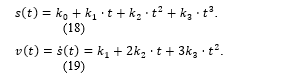
The generic equation of interpolating polynomials with velocity constraints at the two waypoints are:
 where
where
+ s(t) is a cubic polynomial of the path;
+ v(t) is a cubic polynomial velocity respected to s(t);
+ ki, i = 0…3, are polynomial coefficients depended on the arbitrary motion parameters at the two considering waypoints.
To solve the polynomials, the user has to specify the desired velocities at each points as follows:
+ at the initial time ti at : the position value is given ; the velocity value is given ;
+ at the final time tj at : the position value is given ; the velocity value is given .
Equations (18) and (19) are defined as follows:
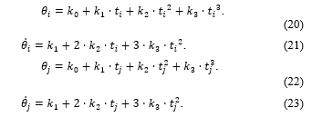 Expressing equations from (20) to (23) in a matrix form, we have the following matrix:
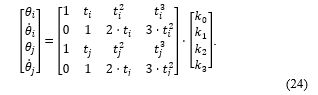 To determine the polynomial coefficients ki, equation (24) can be changed into the following matrix:
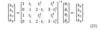 Equation (25) enables the control system planning the desired trajectory independently in pairs of waypoints. The computed velocity command at the waypoints has the following form:
![]() where
where
– is linear velocity for tracking the planned trajectory.
– is angular velocity for tracking the planned trajectory.
The detail calculation of the velocities at the given waypoints can be seen in [20].
3.2. Avoiding obstacle
In the scope of educational goal, let consider an obstacle with a cylinder shape shown in Figure 4. The obstacle stays in segment of path assuming . In this situation, the obstacle have to be avoided by following an additional path to make a suitable curvature in segment .
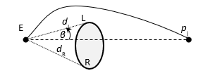 Figure 4: Additional path for avoiding obstacle
Let note the distance to the left obstacle edge L be dL, the distance to the right edge R be dR. and the angle deviation β from the direction to pj to the nearest obstacle edge.
The actuating command for avoiding obstacle are follows:
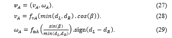 where
where
– and are linear velocity and angular velocity for avoiding obstacle, respectively.
– and are user-defined non-linear functions related to , and for calculating the linear velocity and angular velocity, respectively.
4. Modelling the system with fuzzy-based coordination
Let call the behaviors be planning trajectory PT and avoiding obstacle AO. Then, the AO behavior is divided into 2 simpler behaviors Turning-Left (TL) and Turning-Right (TR) to control the end-effector avoiding a collision by moving to the left or the right edge, respectively. These behaviors are organized in a hierarchical chart shown in Figure 5 and the robot control system can be designed in modules as the block diagram shown in Figure6.
Module PT defines a behavior for planning trajectory and provides a motion command vT to module FC.
Module AO selects a suitable behavior between behavior TL and TR based on the results of obstacle detection and measurement in module DM. Then, an actuating command vA for avoiding obstacle is computed and sent to module FC.
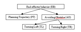 Figure 5: Hierarchical chart for the end-effector behavior
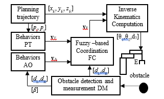 Figure 6: Block diagram of the control system with fuzzy-based coordination
Module FC carries out a fuzzy-based coordination between two behaviors vT and vA to give a suitable actuating command so that the end-effector can avoid the obstacle and reach to path point pj.
The fuzzy-based behavioral coordination mechanism is computed as follows:
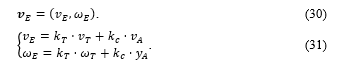 where kT and kC are weights of tracking trajectory and avoiding collision, which are determined by the fuzzy rules as in Table 2.
Table 2: Fuzzy-based estimation of kT and kC
| Fuzzy-based values of kT and kC | β | |||
| small | medium | big | ||
| min (dL,dR) |
Far | kT big,
kC big |
kT big,
kC medium |
kT big,
kC small |
| Middle | kT medium,
kC big |
kT medium,
kC medium |
kT medium,
kC small |
|
| Near | kT small,
kC big |
kT small,
kC medium |
kT small,
kC small |
|
In the next section, the simulations on Matlab are executed under the guide in [21] and [22] to test the control system with the fuzzy-based coordination.
5. Simulation
5.1. GUI interface of simulation
The robot system is tested by a simulation on Matlab. The robot’s motions concerning trajectory and obstacle are tracked and displayed on the GUI interface shown in Figure7.
The left area on the GUI interface displays the coordinates of the three joints concerning the motion and obstacle parameters relative to position and dimensions of height h, long diameter r1 and short diameter r2. The middle area of the GUI interface is a 3D illustration of a truth-based trajectory. The right area is a 2D view of the robot’s workspace and control buttons.
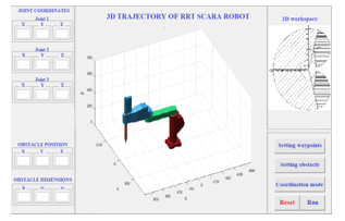 Figure 7: GUI interface of the simulation on Matlab
The five control functions are:
+ “Setting waypoints” button is used for setting the coordinates of each waypoint.
+ “Setting obstacle” button is used for setting the position and dimensions of the obstacle.
+ “Coordination mode” button is used for selecting a coordination mode including conventional coordination without fuzzy logic rules and fuzzy-based coordination.
+ “Reset” button is used for resetting all parameters.
+ “Run” button is used for starting the program.
5.2. Simulation goals and results
Two simulation goals are to test the conventional coordination without fuzzy rules to avoid obstacles and to test the capability of obstacle avoidance under the fuzzy-based coordination.
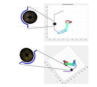 Figure 8: Avoiding obstacle without fuzzy-based coordination
The first simulation results are shown in Figure 8. During following the given waypoints, the robot avoids the obstacle without fuzzy-based coordination. The second simulation results are shown in Figure 9. During following the given waypoints, the robot avoids the obstacle without fuzzy-based coordination.
It is noticed that, the recoded trajectories in Figure 8 are not smooth at the points for changing from a behavior of trajectory planning to a behavior of obstacle avoiding. Otherwise, the recoded ones in Figure 9 become smooth at the points for changing from a behavior of trajectory planning to a behavior of obstacle avoiding due to the fuzzy-based coordination.
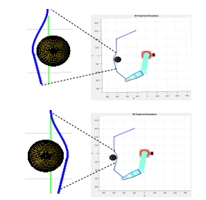 Figure 9: Avoiding obstacle with fuzzy-based coordination
The simulation results in Figure 9 prove that the fuzzy-based coordination make the robot motions non-stop before avoiding obstacle. That means the singularity problem of robotic manipulators can be avoided.
6. Conclusion
The proposed fuzzy-based coordination help the robot safely move and avoid the singularity problem of robotic manipulators.
Matlab simulations are performed to test the performance of the proposed system. Simulation results demonstrate that fuzzy-based coordination helps the robot move more smoothly to eliminate singularity that may appear at dead-points.
In further research, the proposed solution will be tested on a real robot to evaluate the accuracy of trajectory planning after applying the fuzzy-based coordination.
Conflict of Interest
The author declares that there are no conflicts of interest.
- K. Yamafuji, “Development of SCARA robots,” Journal of Robotics and Mechatronics, 31(1), 10–15, 2019, doi:10.20965/jrm.2019.p0010.
- S.M. Raafat, S.M. Mahdi, “Improved Trajectory Tracking Control for a Three Axis SCARA Robot Using Fuzzy Logic,” In IJCCCE, 16(January), 11–19, 2016.
- I.S. Karem, T.A.J. A.Wahabt, M.J. Yahyh, “Design and Implementation for 3-DoF SCARA Robot based PLC,” Al-Khwarizmi Engineering Journal, 13(2), 40–50, 2017, doi:10.22153/kej.2017.01.002.
- U.T. Nasional, C. Engineering, “Design and development of 4-DoF SCARA robot for educational purposes,” Teknologi, 54(1), 193–215, 2011, doi:10.11113/jt.v54.810.
- F. Cao, J. Liu, C. Zhou, Y. Zhao, Z. Fu, W. Yan, “A Novel 5-DOF Welding Robot Based on SCARA,” in in 10th IEEE Conference on Industrial Electronics and Applications (ICIEA), 2016–2019, 2016, doi:10.1109/ICIEA.2015.7334444.
- M. Abu Qassem, I. Abuhadrous, H. Elaydi, “Simulation and Interfacing of 5 DOF Educational Robot Arm,” in Proceedings – 2nd IEEE International Conference on Advanced Computer Control, ICACC 2010, 569–574, 2010, doi:10.1109/ICACC.2010.5487136.
- N.A. Mai, X.B. Duong, “Algorithm for improving feeding rates of industrial welding robot TA 1400 in combination with a turntable frame,” Computer Science and Cybernetics, 3(3), 285–294, 2020, doi:10.15625/1813-9663/36/3/14968.
- N.A. Mai, X.B. Duong, “Voice Recognition and Inverse Kinematics Control for a Redundant Manipulator Based on a Multilayer Artificial,” Hindawi Robotics, 2021, 1–10, 2021, doi:10.1155/2021/5805232.
- E.C. Agbaraji, H.C. Inyiama, C.C. Okezie, “Dynamic Modeling of a 3-DOF Articulated Robotic Manipulator Based on Independent Joint Scheme,” Physical Science International Journal, 15(1), 1–10, 2017, doi:10.9734/PSIJ/2017/33578.
- T. Taunyazov, M. Rubagotti, A. Shintemirov, “Constrained Orientation Control of a Spherical Parallel Manipulator via Online Convex Optimization,” IEEE/ASME Transactions on Mechatronics, 23(1), 252–261, 2018.
- K. Wei, B. Ren, “A Method on Dynamic Path Planning for Robotic Manipulator Autonomous Obstacle Avoidance Based on an Improved RRT Algorithm,” MDPI Special Issue Smart Sensors for Mechatronic and Robotic Systems, 18(2), 571–585, 2018, doi:10.3390/s18020571.
- A. Prasad, B. Sharma, J. Vanualailai, “Motion Control of a Pair of Cylindrical Manipulators in a Constrained 3-dimensional Workspace,” in 4th Asia-Pacific World Congress on Computer Science and Engineering (APWC on CSE), 75–81, 2017, doi:10.1109/APWConCSE.2017.00022.
- A. Suarez, M. Perez, G. Heredia, “Cartesian Aerial Manipulator with Compliant Arm,” MDPI Special Issue Aerial Robotics for Inspection and Maintenance, 11(3), 1001–1020, 2021.
- M.Z.A.- Faiz, A.M. Abbass, “Design and Implementation of Fuzzy Logic Controller for IVAX SCARA Robot Using Real Time Window Target,” JCSET, 3(10), 373–381, 2013.
- D. Prabu;, S. Kumar;, R. Prasad, “Dynamic Control of Three-Link SCARA Manipulator using Adaptive Neuro Fuzzy Inference System,” in 2008 IEEE International Conference on Networking, Sensing and Control, 1609–1614, 2008.
- P.G.. Zavlangas, S.G. Tzafestas, “Industrial Robot Navigation and Obstacle Avoidance Employing Fuzzy Logic,” Intelligent & Robotic Systems, 27(1), 85–97, 2000, doi:10.1023/A:1008150113712.
- Y. Chen, Y. Wang, “Obstacle avoidance path planning strategy for robot arm based on fuzzy logic,” in 12th International Conference on Control Automation Robotics & Vision (ICARCV), 5–7, 2012, doi:10.1109/ICARCV.2012.6485438.
- H.C. Nguyen, H.X. Nguyen, N.A. Mai, L.B. Dang, H.M. Pham, “A Modular Design Process for Developing Humanoid Mobile Robot Viebot,” Advances in Science, Technology and Engineering Systems Journal (ASTES), 3(4), 230–235, 2018.
- R.M. Murray, A Mathematical Introduction to Robotic Manipulation, CRC press, 1994.
- L. Sciavicco, B. Siciliano, Modelling and Control of Robot Manipulators, Springer, 2000.
- S. Shrivastava, “Matlab guide for forward kinematic calculation of 3 to 6 DoF SCARA robots,” IJRET, 6(8), 46–52, 2017, doi:10.15623/ijret.2017.0609009.
- M.F. Aly, A.T. Abbas, “Simulation of obstacles ’ effect on industrial robots ’ working space using genetic algorithm,” King Saud University – Engineering Sciences, 26, 132–143, 2014, doi:10.1016/j.jksues.2012.12.005.
No related articles were found.