Service Lifetime Loss Evaluation Method for Transformers Exclusively Serving Solar Power Plants

Adv. Sci. Technol. Eng. Syst. J. 6(6), 22–28 (2021);
 DOI: 10.25046/aj060604
In the last decade, South Africa has attracted and attained more investment by means of the Renewable Energy Independent Power Producer Procurement Programme (REI4P), which is, a structured invitation to Independent Power Producers (IPPs) to submit a bid to generate and supply power to the electrical grid. In spite of REI4P’s undeniable triumph, a much-discussed drawback has been the related service lifetime cost of equipment that facilitate the renewable energy technologies. The description of the service lifetime loss method (SLLM) gets more complex in the new dawn of decarbonized electricity market. The SLLM must be modified for determining the total ownership cost of transformers facilitating Sustainable Energy Systems (SES’s) in the decentralized energy market. The main focus of this work is to indicatively formulate a fundamental advancement upon the conventional service lifetime losses evaluation formula to contemplate the service lifetime loss evaluation method for transformers exclusively of service to solar power plants in South Africa. The distinct operational features of a solar plant have been embedded in the formulated service lifetime loss evaluation formula by way of the plants’ Generation (GM) and Non-Generation Mode (NGM). Further, a levelized cost of energy supplied per unit of time by the solar plant is employed to determine the energy cost of the no-load and load losses that will be consumed by the studied transformers during their service life. Ultimately, the premier findings of this study indicate that the annual solar potential has an effect on the transformer service lifetime loss factors and the conventional method is not suitable thereof for this application. This is a characteristic that should be precisely considered, as it may influence the tender adjudication process to purchase a transformer based on the total ownership cost offers of various transformer manufacturers.
1. Introduction
The rapidly escalating cost of energy from coal power generation in South Africa has aroused a substantial demand for feasible recourse energy sources. In spite of the fact that at present it contributes to only a small proportion of South Africa’s power generation, deployment of solar power plants (SPPs) is rapidly increasing for both utility-scale and distribute generation power generation systems (DPGS). Reduction of the energy tariffs are impelled by the technological advances, proportionate saving in costs gained by an increased level of production in manufacturing, and novelties in finance has introduced solar power at arm’s length of grid parity in an increasing renewable energy markets. Ongoing advances and additional cost savings will broaden these window of opportunities especially in South Africa where opportune solar conditions prevail. The energy tariffs for renewable energy technologies has been incessantly plummeting since the inception of the Integrated Resource Plan (IRP) [1] and [2]. Figure 1 shows the annualized cost of energy (ACOE) for wind and solar [3]. Wind and solar photovoltaic (PV) are observed to cost about 0.91 ZAR/kW and 0.755 ZAR/kW while coal-based energy cost about 1.03 ZAR/kW [3].
Meanwhile the rapid increase of the South African energy mix has been attended by an observed uneven proficiency revealed the new dawn of renewable energy market. For instance, the energy mix in South Africa by the vertically-integrated utility and Independent Power Producers (IPP’s) exist together at the same time but have distinctive methodologies of evaluating their capital expenses, network expenditures and load curves. Therefore, the processes for the transformer loss capitalization must be distinctive. The methods available in the literature straggle the proficiency to appropriately unbundle the loading and energy components of the cost transformer losses in the concerned entities. This will significantly guarantee that each loss component is apportioned to suitable stakeholders in decentralized energy markets with regards to who is accountable to insure the losses of the transformer.
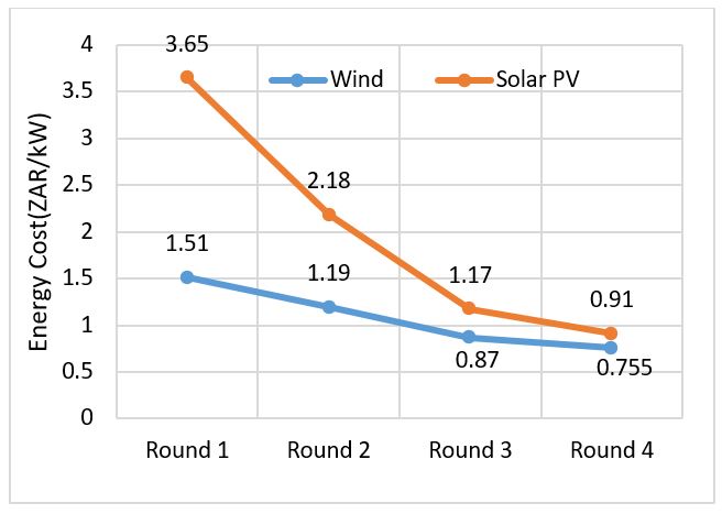 Figure 1: Energy tariffs for Wind and Solar in South Africa
Transformers are often anticipated to be in service between 25-30 years [4]. The jurisdiction procedure by utility owners for purchasing a transformer should therefore not only be based on the initial purchase cost but also the operating and maintenance costs. The total ownership cost (TOC) method [5] take into consideration the purchase cost, operational cost and maintenance costs over the transformer designed service lifetime. It has become possible for utility owners to compute the most technical and economic choice between competing transformer designs over its designed service lifetime through the TOC method. The TOC method also incorporates other cost related parameters such as annualized cost of electricity (ACOE), discount rates, tax rates et cetera. Considering that the TOC method comprises of the cost of service losses, in which will materialize in the future, there is a need to discount these losses to equalize them to current day South African rand (ZAR) value. The capitalization values cost of no-load loss (CNLL) and cost of load losses (CLL) in ZAR⁄kW studied by authors in [6 – 10] derive the cost of service losses. Transformer manufacturers submit a technical and commercial offer in a competitive bid and if the capitalization values are provided, then the manufactures should be grounded on these values in all cases. The service no-load losses are reliant on the core steel grade and are unvarying for a transformer during service [11] and [12]. The service load losses on the other side are dependent on the loading profile of the transformer [13] and [14]. Significant service losses of a transformer during service can potentially culminate in excessive heating and consequently degradation of insulation of materials due to overloading and presence of harmonics especially in renewable energy technologies suchlike wind and solar [15] – [20]. As a result, a low-loss transformer would practically be in service for a longer duration with minimum potential for premature failure. Additionally, a low-loss transformer discounts the amount of electrical energy necessitated to supply the service losses.
Firstly, this work presents classical SLLM for transformers that are intended to be in service for 8760 hours annually and from a single utility energy source. This method is based on transformer loss data supplied by the manufacturers and the utility characteristics.
Nevertheless, the understanding of the SLLM becomes knotty within the bounds of transformers intended to be of service to renewable energy application. A SLLM for solar power plants is then proposed in this work. This method corrected the classical method intended for transformers intended to be in service for 8760 hours annually and from a single utility energy source. In the case of solar power plants, during the non-generating period, the solar plant will be feeding-off the electric grid with coal power generation
2. Transformer cost analysis
In order to bestow the surged energy demand, the excessive loading of transformers during service and related remaining service lifetime on account of the hotspot temperature rise is structural components must be cautiously estimated in opposition to the replacement of transformers or supplementing existing unit with new transformer. IPP’s generally ascertain definitely the size of suitable units for service based on current loading cycle, forecasted load growth and other sound engineering acumen. Additionally, IPP’s determine the economic effect of service losses of the transformer over its planned service lifetime and the initial purchase price prior to procuring new transformers. The classical Total Ownership Cost (TOC) procedure provides a comprehensive analysis for the economic planning aspects of investing in purchasing and operating a transformer
2.1. Service lifetime loss method: Classical Method
The purchasing of transformers by SLLM is predominantly employed based on the premise of a lowest TOC amongst competing offers of various transformer manufacturers. This method provide details on the cost of transformer service losses and the initial purchasing price of the unit. The service lifetime of the unit is presumed to be even irrespective of the MVA rating. Various transformer loading guides suggest a normal operating service lifetime of 30 years [4]. The aspect of investing in purchasing a transformer is determined to reflect an annual cost of the service no-load and load losses inclusive of the demand rate. The total revenue needed is treated by the ratio of the annual cost of these losses to the fixed charge rate (FCR). The FCR illustrates all the incurred charges in the utility independent of energy (kWh) traded, suchlike depreciation, tax, insurance and service maintenance.
For each unit of kilowatt (kW) of the service no-load and load losses, there is an inclusion of the demand cost (DC) portion derived from capital cost of the transformer. Consequently, there is an inclusion of the component for the energy cost (EC) in kilowatt-hour (kWh) by the utility. The cost of service losses (CSL) are hence computed as follows in (1).
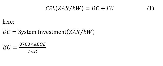 System investment (SI) illustrates the acquisition in the bulk movement of electrical energy from a generating site to distribution facilities essential to deliver supplementary energy demand arising from transformer service losses at the system peak. There are essentially two approaches to assessing the SI rate in ZAR/kW. The first one is classical and is based on the established costs of constructing a generating site and related distribution facilities. The second approach is based on a scenario where the power utility does not self-generate power and instead purchase power. The SI rate can be ascertained by ratio of the DC (ZAR/kW-yr.) and the FCR.
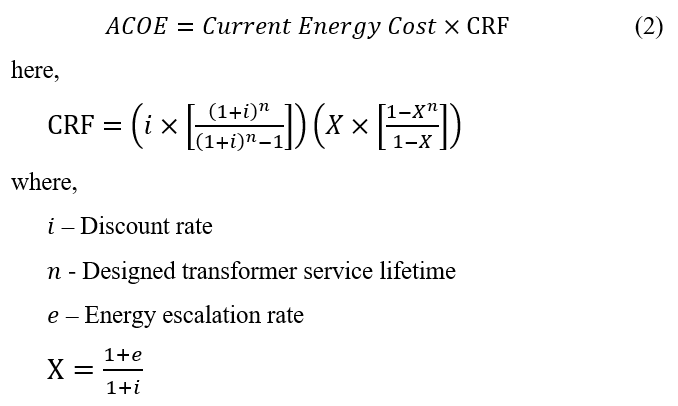
Consequently, the ACOE is evaluated by forecasting and weighting the annual inflated cost of energy by means of capital recovery factor (CRF). Analytically, the latter can be expressed as shown in (2).
 It follows that the cost of losses can be expressed as follows in (3). This equation is handily feasible for power utilities with their own electricity generation.
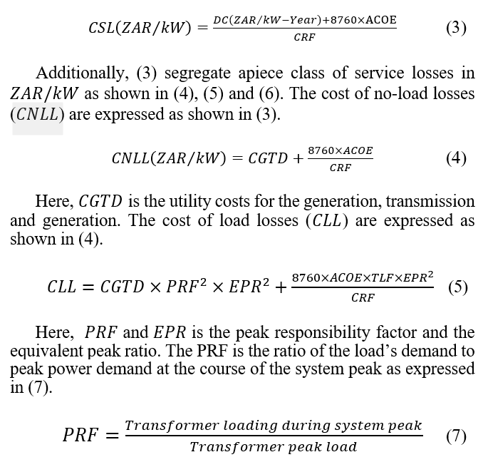
The PRF can be implemented to unique customer classes. Needless to say that a loading with a PRF of one peaks concurrently with the overall system. The electrical loading of particular customer classes have a propensity to fluctuate at a similar fashion. For instance in South Africa, commercial electrical load are at peak from about 08:00AM in the morning to about 18:00PM in the evenings while residential electrical loads peak from around 18:00PM in the evenings. Inevitably, the weather has a direct impact on the loading extent. In the winter for instance, electrical heaters increase the demand and lower the variety among loads. At the distribution transformer level, the loading factors are largely ranging from about 0.4 to 0.9 with 0.75 being common [6 – 8] and [10]. The standard values of PRF can vary from 1.0 to about 0.35. Given that PRF is a ratio based on the loading (kVA), the services losses are a function of based on transformer manufacturers empirical survey. The most common values of the PRF for various transformers is tabulated in Table 1.
Table 1: PRF values for various transformer classes
| Power System Level | PRF |
| Generator Step-Up | 1 |
| Transmission Substation | 0.9 |
| Distribution Substation | 0.8 |
| Distribution | 0.35 |
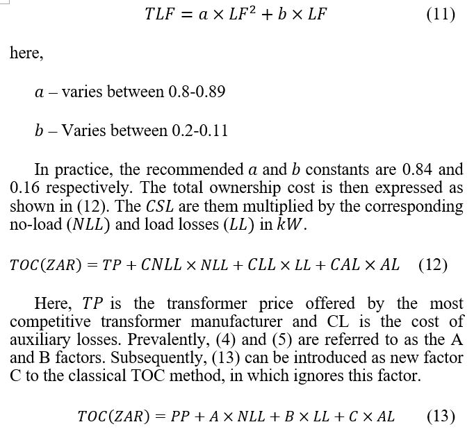
The interrelation between the service losses and the rated transformer loading is described by the peak ratio. The latter can be expressed analytically as follows in (8).
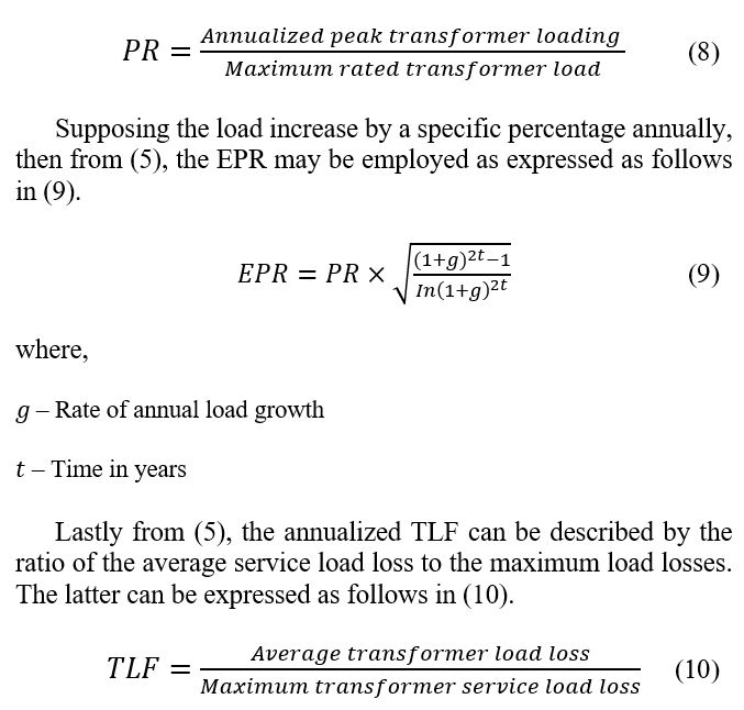
If the power utility provides the annual loading cycle data, then the services load losses can be evaluated from this data. Nevertheless, the utility owners endeavour to link up the transformer service loss factor with a more easily accessible information viz. the load factor (LF). The determination of the TLF is dependable on some empirical data and can then be evaluated as expressed in (11) [11].
2.2. Service lifetime loss method: Proposed Method
A majority of SPP’s in South Africa are owned by the Independent Power Producers (IPP’s). The plant consists of an array of solar photovoltaics modules connected in series and thereupon connected to an inverter that carries out the direct current (DC) to alternating current (AC) conversion. Furthermore, a step-up transformer is connected to the inverter output to increase the voltage to the desired transmission voltage level. Transformers in SPP’s are connected on a permanent basis to the electric grid to guarantee the plant is fed with power to fulfil its auxiliary losses during non-generating mode (NGM). The energy cost of the coal power generation ( ) will be affected in this regard. Conversely, during SPPs generation mode ( ) the solar irradiation is available and the solar modules can harvest power. Only, the energy cost of the solar PV ( ) in kWh will be affected.
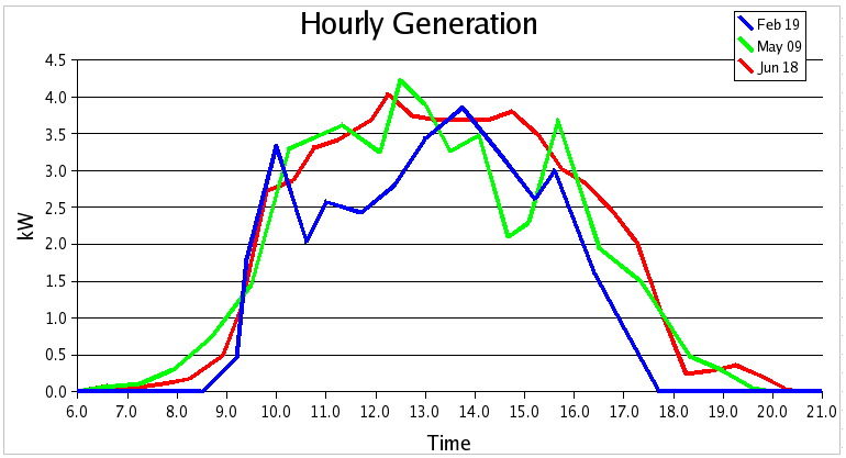 Figure 2: SPP generation profile in South Africa
Figure 2 demonstrate a solar PV generation profile of a SPP as acquired by field measurements and the data is collected over the period of five months. It should be noted that the SPP profile is reliant on the effective average daily solar radiation profile on the surface area of the solar PV modules and corresponding solar PV technology. As demonstrated in Figure 2, the GM of the SPP can be described by the affective area under the curve between the period 08:30AM to about 18:30PM
The generation modes of the SPP generation profile is then tabulated as shown in Table 2. A 24-hours generation state is considered in the analysis and about 14 hours the solar radiation will be available for the solar modules to harvest power (GM) while bout 10hours of that time the sun will be down (NGM). The ratios of GM and NGM against the 24-hours daily generation state result in the generating (FGM) and non-generation factors (FNGM)
It is reaffirmed that the proposed SLLM proposed in this work is relevant to Independent Photovoltaic Power Producers
Table 2: Generation modes: solar power plant
| Generating State | 24 hours |
| GM (Hours) | 14 |
| NGM (Hours) | 10 |
| FGM | 0,583 |
| FNGM | 0,417 |
(I3P) supplying electricity to the electric grid by means of step-up transformer. The critical element in capitalizing the service losses in these transformers is the correct definition of the energy component of the cost of service no-load ( ) and load losses ( ). The energy component is the current energy tariff that will be utilised by a unit kilowatt (kW) of each service loss over the course of designed service lifetime of the SPP. In (14), the proposed method to evaluate the for transformer intended to operate in SPP. Over the course of the day, the SPP has a greater likelihood to operate GM and NGM. Whenever, the SPP is operating in GM, then it is solely accountable to generate, solely supply of energy and service loss demands as well as transmission of energy to the electric grid. Conversely, during the course of NGM, the SPP purchase energy in a South African context from a coal power generation utility in order to supply its auxiliary requirements and losses. The latter is expressed by (14).
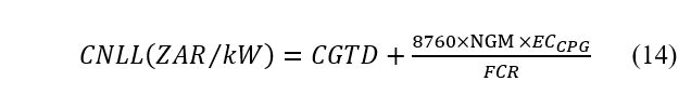 In this case, the energy tariff of the coal power generation utility ( ) applies. Moreover, the annual operating hours are weighted in accordance with the availability of the solar radiation. In (15), the case of the evaluating for the cost of service load losses for transformers intended for SPP is also demonstrated by improving (5) from the previous section. The energy tariff of the SPP ( ) and corresponding generating factor is considered when the plant is generating its power.
 Additionally, NGM component is added into the formulation to take into account for the when the transformer is operated in reverse as a step-down transformer to supply the auxiliary and loss requirements of the SSP from the grid supply.
3. Case Study: 1500KVA oil-immersed transformer
In this section, the data in Table 3 is considered to conduct the service lifetime loss evaluation. The data is intended to make a substantiated decision to purchase a 1500kVA oil-immersed transformer with 65 ℃ mean winding temperature. Transformer designs from three distinct manufactures will be considered in this case study. Each design attempt to attain coveted specifications with cost-effective materials, minimum dimensions and lowest overall cost of transformer ownership. In South Africa, increasingly in South Africa, utility owners now purchasing transformers on the basis of the transformer TOC over its intended service lifetime, than just the purchasing price.
Table 3: Service lifetime parameters
| Parameter | Value |
| Designed Service Lifetime | 30 years |
| No. of service hours per year | 8760 |
| Annualized Energy Cost | 0,61 ZAR/kW |
| Fixed Charge Rate (FCR) | 0,192 |
| System Investment (SI) | 23000 ZAR/kW |
| Discount Rate (i) | 10,00% |
| Energy Escalation rate (i) | 2,00% |
| Load Factor (LF) | 0,6 |
| TLF | 0,3984 |
| EPR | 0,97 |
| Peak Responsibility Factor (PRF) | 0,6 |
| Peak Ratio (PR) | 0,7 |
| Load Growth Rate (LGR) | 2,00% |
| Coal | 1,03 ZAR/kW |
In Table 4, a design comparison (A, B and C) of the service losses, selling prices and respective cost of service losses and TOC is presented for three different competing transformer manufacturers. This information is useful in the jurisdiction of the more technically and economically suitable transformer. Design A is the highest loss design of the three offers. Design B and C are lower loss designs. Manufacturer B and C on that account have used better grades of core steel, optimized conductor dimensions and improved cooling medium and procedures
Table 4: Service lifetime loss analysis: classical method
| Mn | NLL | LL | SP | CLL | TOC |
| A | 6 | 25 | R460,839 | R970 966 | R1,431,806 |
| B | 5 | 20 | R510,215 | R789 677 | R1,299,892 |
| C | 5 | 16 | R559,591 | R696 260 | R1,255,851 |
In Table 4, the classical TOC method has been employed to evaluate the SLLM. This method makes the assumption that the transformer will be in service for 8760 days annually over its designed service lifetime. This premise does not however hold true for renewable energy applications considering the spasmodic nature of renewable energy sources. In Table 5, the proposed solar power plant procedure for evaluating the SLLM is presented. This method takes into consideration the GM and NGM of the plant over the designed transformer service lifetime as described in the previous section. Design C is observed to have lower service losses in comparison to manufacturer B and C even though the selling price of the manufacturer is higher. It follows that the TOC of the unit is also lower over the normal operating service lifetime
Table 5: Service lifetime loss analysis: solar PV method
| Mn | NLL | LL | SP | CLL | TOC |
| A | 6 | 25 | R460,839 | R737,986 | R1,198,825 |
| B | 5 | 20 | R510,215 | R597,308 | R1,107,523 |
| C | 5 | 16 | R559,591 | R512,443 | R1,072,033 |
The case studies in Table 4 and Table 5 illustrate that cost of the transformer service losses over the transformer designed lifetime are critical to evaluate over just the purchase price.
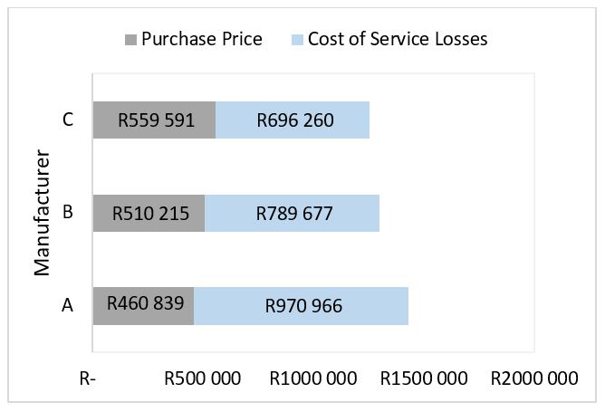 Figure 3: TOC of the transformer manufacturers: Classical method
The results in Figure 3 indicate that manufacturer C has the highest purchase price in comparison to manufacturer B and C by 9% and 18 % respectively. Additionally, the CSL for manufacturer C is lower by 13% and 39% respectively over the designed service lifetime. By employing the classical method, this results indicate that over the designed service lifetime of the transformer under study the IPP can purchase the most expensive transformer while keeping a relatively lower cost of service losses over the intended transformer lifetime. Alternatively, the IPP can choose the cheapest transformer offer with significantly higher service losses over the designed lifetime. However, from a maintenance perspective of the IPPP the later will not be economical.
Results of the proposed SLLM for the three transformer offers are presented in Figure 4. As indicated earlier, throughout the day the SPP will undoubtedly operate in two modes. When the plant is operating in GM, the SSP is accountable to supply its own energy and losses in addition to supplying power to the electric grid. When the SSP is operating on the NGM, then auxiliary requirements of the SSP will be supplied by the electric grid, that is to say that the SPP will purchase power from the coal power generation utility and their energy tariffs will apply.
Figure 4, the results indicate that manufacturer A has the cheapest purchase price and highest CSL. Manufacturer B is the second cheapest offer while manufacturer C is more expensive. The CSL is cheaper by 44% and 17% in comparison to manufacturer A and B respectively. In this regard, the most techno-economical purchase decision for the IPP will be that of manufacturer C.
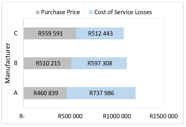 Figure 4: TOC of the transformer manufacturers: Solar power plants
In order to demonstrate the differences between the classical and proposed SPP SLLMs, Figure 5 is presented. It can be observed from Figure 3 and Figure 4 that the transformer offers from each respective method that manufacturer C has a significantly higher selling price but is more economical over the 30 years designed service lifetime.
Manufacturer B and C have managed to optimise their no-load losses by 17% in comparison to manufacturer A. in practice, this loss is minimised by four methods:
- Enhancement of the core steel construction
- Enhanced cutting of the core laminations and employing step-lapped joints as they interleave the core laminations that connect the joint gap.
- Enhancement of the core laminations stacking; and
- Computational modelling of the no-load losses.
The use of amorphous steel in the transformer design also plays a critical role and can minimise the no-load loss by 70-80% as opposed to silicon graded core steel.
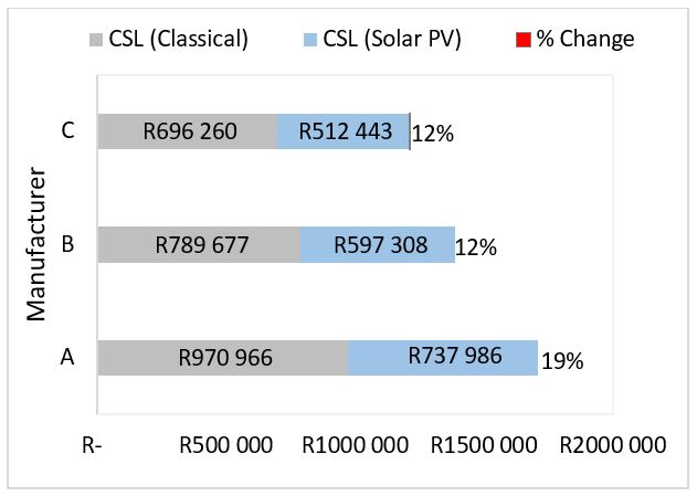 Figure 5: TOC of the transformer manufacturers: Comparison
Overall, manufacturer C has managed to optimise the service load losses by 56% and 25% in comparison to manufacturer A and B respectively. In practice, the service load losses is instrumental to the efficiency of the transformer during service. It therefore critical to reduce these losses for the purpose of enhancing and achieving the most optimal service performance. Reduction of the load loss is treated by the selection of large conductor dimensions in the interest of minimizing the resistance per unit length of winding conductors. A comparison of the CSL between manufacturer A and B is 12% while between manufacturer A and manufacturer C it is 19%.
The results presented in Figure 5, show some benefits of using the proposed method over the classical method. Taking into consideration the generation modes of the SPP and the ACOE has some techno-economic benefits for the IPP.
4. Conclusion
This work proposes a holistic SLLM to compute the TOC of transformers designed to be of service to solar power plants. These transformers are predominantly owned by IPP’s in South Africa. More notably, the proposed method acknowledge precisely how the cost of the service no-load and load losses should be calculated, taking into consideration the TOC of the transformer in relation to the operational requirements of solar power plants they operate in. The distinct operational features of a SPP have been incorporated in the classical SLLM by means of the two generating modes (GM and NGM). Additionally, the proposed SLLM for the transformer under study is influenced by the reality that this transformer will exclusively facilitate the SSP, as distinguished from another generation utility. As a result the ACOE for SPP in South Africa is employed to evaluate the CSL that will be consumed by the transformer under study during service. At large, it is shown that the solar irradiation plays a pivotal role on the calculation of the CNLL and CLL. This is a property of the SPP that should be cautiously covered, as it may influence the tender jurisdiction criterion to choose the lowest TOC of a transformer over its designed service lifetime.
The insights gained in this work indicate that most economical transformer purchase choice for SPP owners is a high purchase price and low-cost transformer over low-purchase price and high-loss transformer.
Conflict of Interest
The authors declare no conflict of interest.
- Department of Energy, “Executive Summary of the Draft Integrated Electricity Resource Plan for South Africa – 2010 to 2030 IRP 2010,” in Department of Energy, 2010, doi: executive-summary-draft-integrated-electricity-resource-plan-south-africa-2010-2030-irp
- Department of Energy, “Integrated Resource Plan 2019, in Department of Mineral Resources and Energy, 2019, doi: IRP/2019/IRP-2019.pdf.
- J. Calitz, C. Mushwana and T. Bischof-Niemz, “Statistics of utility-scale solar PV, wind and CSP in South Africa in 2016,” in CSIR Energy Centre, 2017.
- K.S. Takayuki, K.T. Kobayashi, “How Transformers Age,” in T&D World, 2019, doi: substations/article/20972255/how-transformers-age.
- A. Indarto, I. Garniwa, R. Setiabudy and C. Hudaya, “Total cost of ownership analysis of 60 MVA 150/120 kV power transformer,” 2017 15th International Conference on Quality in Research (QiR) : International Symposium on Electrical and Computer Engineering, Nusa Dua, 291-295, 2017, doi: 10.1109/QIR.2017.8168499.
- A. L. Lazari and C. A. Charalambous, “Life-cycle loss evaluation of power transformers serving large photovoltaic plants in vertically integrated and decentralised systems,” in IET Generation, Transmission & Distribution, 9 (8), 759-766, 2015, doi: 10.1049/iet-gtd.2014.0465.
- T. Knutson, “Conducting Distribution Transformer Evaluations Using the Total Ownership Cost Method,” 2015 IEEE Rural Electric Power Conference, Asheville, NC, 97-101, 2015, doi: 10.1109/REPC.2015.14.
- C. A. Charalambous, A. Milidonis, S. Hirodontis and A. Lazari, “Loss Evaluation and Total Ownership Cost of Power Transformers—Part II: Application of Method and Numerical Results,” in IEEE Transactions on Power Delivery, 28 (3), 1881-1889, 2013, doi: 10.1109/TPWRD.2013.2262507.
- A. Eliasson, H. Elvfing and V. R. Ramanan, “Amorphous Metal core material shows economic and environmental benefits when pre-existing transformers are to be replaced within Vattenfall Group´s distribution network,” 2010 IEEE PES Innovative Smart Grid Technologies Conference Europe (ISGT Europe), Gothenberg, 1-7, 2010, doi: 10.1109/ISGTEUROPE.2010.5638963.
- A. L. Lazari and C. A. Charalambous, “Probabilistic Total Ownership Cost of Power Transformers Serving Large-Scale Wind Plants in Liberalized Electricity Markets,” in IEEE Transactions on Power Delivery, 30 (4), 1923-1930, 2015, doi: 10.1109/TPWRD.2014.2365832.
- IEEE Guide for Transformer Loss Measurement – Redline,” in IEEE Std. C57.123-2019 (Revision of IEEE Std C57.123-2010) – Redline, 1-86, 2020, doi: 10.1109/IEEESTD.2010.5954117.
- J. Wojtkun, B. Bródka and D. Stachowiak, “The influence of core geometry on no-load losses of medium power transformers,” 2018 International Interdisciplinary PhD Workshop (IIPhDW), Swinouj?cie, 123-127, 2018, doi: 10.1109/IIPHDW.2018.8388339.
- P. Tandeaw, C. Manop and N. Jirasuwankul, “Design and Testing of Low Loss Distribution Transformer for Non-Linear Loading Current,” 2018 International Electrical Engineering Congress (iEECON), Krabi, Thailand, 1-4, 2018, doi: 10.1109/IEECON.2018.8712270.
- S. Taheri, H. Taheri, I. Fofana, H. Hemmatjou and A. Gholami, “Effect of power system harmonics on transformer loading capability and hot spot temperature,” 2012 25th IEEE Canadian Conference on Electrical and Computer Engineering (CCECE), Montreal, QC, 1-4, 2012, doi: 10.1109/CCECE.2012.6334834.
- B.A Thango, D.B Nyandeni, P.M Molepo J.A Jordaan, A.F Nnachi, “Solar Power Plant Transformer Loss Computation under Harmonic Currents using Finite Element Method”, 9th CIGRE Southern Africa Regional Conference, 2019.
- D.B. Nyandeni, M Phoshoko (Pr. Eng.), R Murray, BA Thango, “Transformer Oil Degradation on PV Plants – A Case Study”, 8th South Africa regional conference, 14-17, 2017,
- A. Bonginkosi Thango, Jacobus A. Jordaan, Agha F. Nnachi, “Effects of Current Harmonics on Maximum Loading Capability for Solar Power Plant Transformers”, 2020 International SAUPEC/RobMech/PRASA Conference, 1-5, 2020, doi: 10.1109/SAUPEC/RobMech/PRASA48453.2020.9041101.
- A. Elmoudi, M. Lehtonen, H. Nordman, “Effect of harmonic on transformers loss of life”, in: Conference Record of IEEE International Symposium on Electrical Insulation, 2, 408-411, 2006.
- R. Singh and A. Singh, “Aging of distribution transformers due to harmonics,” Proceedings of 14th International Conference on Harmonics and Quality of Power – ICHQP 2010, Bergamo, 1-8, 2010.
- B. A. Thango, J. A. Jordaan and A. F. Nnachi, “Selection and Rating of the Step-up Transformer for Renewable Energy Application,” in SAIEE Africa Research Journal, 111(2), 50-55, 2020, doi: 10.23919/SAIEE.2020.9099492.