Study and Implementation of LEDs Drivers with Dimming Capability

Adv. Sci. Technol. Eng. Syst. J. 6(6), 130–136 (2021);
 DOI: 10.25046/aj060617
Nowadays, LED lights take an important place in our daily lives and they have known a great growth in indoor as well as in outdoor lighting applications. LED (Light Emitting Diode) light sources including their own drivers have excluded many systems fitted with both inefficient light sources. In this paper we present, a LED driver handling a DC input power supply and piloting a series of powered LEDs Some topologies of LED driver supplying a constant voltage or a constant current toward a LED load and their operations are detailed and presented. In this regard, two types of DC-DC converter in occurrence buck and boost converter are analyzed, designed, and simulated. Furthermore, a design of laboratory prototype of constant-current LED drivers based on DC-DC buck converter totally dimed is achieved, and tested. Calculated and experimental results are in good correspondence with very small deviation of LED current in both cases for different levels of dimming.
1. Introduction
Light Emitting Diodes (LEDs) usage has known an extra ordinary growth in indoor and outdoor lighting applications. Consequently, nowadays LED lights take an important place in our daily lives and have become a viable alternative to conventional low efficiency light sources like incandescent, CFL (compact fluorescent lamp) and HID (high intensity discharge) lamps. LED lighting systems have better characteristics than conventional lighting systems such as energy saving, long life spans and color rendering [1]-[8] and they play an important role in future indoor as well as outdoor lighting applications. To operate properly with respect of energy saving, high efficiency and minimum electric constraints, these light sources demand a specific driver. These LED drivers play an important role on the type of lighting system performances, such as dimming capability, power quality, Light quality and product lifetime.
The overall lighting system efficiency is affected by the choice of driver’s topology and the associated electronic components. For outdoor applications some other constraints must be added to those known before such as humidity and ambient temperature. In indoor applications, the drivers are integrated in the luminaries in order to make them compact and facilitate their integration in any decoration [9].
Two principal electronic circuits are used to drive LEDs under specific electrical conditions: constant current (CC) or constant voltage (CV) [10]-[15]. Such drivers, should also satisfy intensity and color requirements of LEDs.
In the second section of this paper, after a short presentation on the fundamentals and characteristics of LEDs and their driver circuits, we present the operating principles and the design of DC-DC buck converter and boost converter used to drive LEDs with current and voltage regulation. by varying voltage source respectively. The DC-DC converter can supply LEDs up to 1A current and insure full dimming of rated current. The third section of this paper, describes the design and discussion of these converters and their control. Finally, in sections 4 and 5, some simulations and experimental results are given for a DC-DC buck converter four LED light-spot connected in series and mounted on a board drawing 300mA rated current.
2. LEDs and LEDs drivers
2.1. LEDs
LEDs are made of doped gallium nitride (GaN) semiconductor material. Their electronic structure is a diodes or tandem structures, [16]. Power LEDs are by their superior life time, cost-effective, and high luminous intensity compared to classical incandesent lamp and low pressure discharge lamp. Nevertherless, they are known by low environment impact and they are used solid-state lighting source in many lighting applications. Power LEDs light sources are presented in figure 1, they require 2 to 4V of dc forward voltage and several hundred mA of dc forward current for their optimal operating point [17].
 Figure 1: Samples of power LEDs
A powerful light spot, is made by combining small LED array devices according different matrix architectures. In addition, it’s required to take account of some LEDs characteristics when using them, such as:
- Their electric characteristics, light output and the color of the emitted light are sensitive to the temperature.
- The forward voltage of high-Power LED changes with temperature which will cause drawing more current. The relation between VF (Forward Voltage) and temperature is reverse as shown in Figure When the temperature increases, forward voltage decreases, this is known as Thermal Runaway, which causes a semiconductor failure. [16].
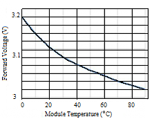 Figure 2: Forward voltage versus Temperature for LED
Stable temperature and dc current as much as possible increases the reliability and guaranties the longest life of LEDs.
3. LEDs Drivers
LEDs need equipment called a “driver” for their supply and control. Many topologies of LED drivers are deployed and many special ICs are available and used to support these different topologies. Two kinds of drivers are commonly employed to drive LEDs:
- Constant-Voltage regulated drivers able to maintain a DC output voltage. regardless variation of input voltage or output current within specified limits.
- Constant-Current regulated drivers able to maintain a DC output current regardless variation of input voltage or output voltage within specified limits [18].
Converter topologies such as buck, boost, or buck-boost converters are widely employed for LED drivers [19]-[23].
3.1. DC-DC converter
Llinear DC-DC converters and switched-mode DC-DC converters are among the converters used for DC-DC conversion function. They can deliver different dc voltage level from dc voltage source and they often provide a regulated output.
· Linear DC-DC converter
Figure 3 shows a linear DC-DC converter.
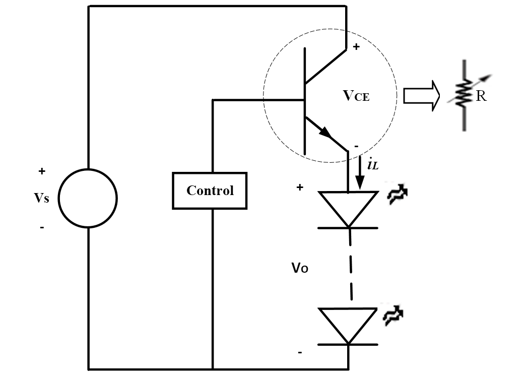 Figure 3: A basic linear regulator
The load current iL is controlled by adjusting the transistor dc biasing, the output voltage may be controlled over a range of 0 to roughly Vs. The transistor in effect operates as a variable resistance. The low efficiency of this circuit is a serious drawback for power applications caused by BJT( Bipolar Junction Transistor) losses.
· Switched-mode DC-DC converters
In a switching mode, the MOSFET operates as an electronic switch by being totally ON or totally OFF [24]. In the chopper circuit of figure 4 (a), the output is the same as the input when the switch is closed during DT, and it’s zero when the switch is open. Figure 4 (b) shows the output voltage across the load.
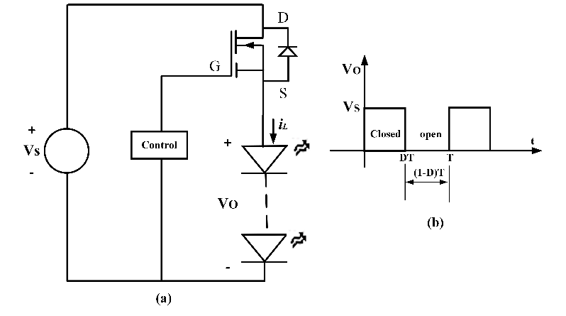 Figure 4: (a) Switching converter (b) Output voltage
The output average voltage is: Vo = DVS and thus it’s less than the input voltage and its dc component can be controlled by adjusting D. Such converter is nominated buck converter. For boost converter, the voltage Vo is always higher than the supply voltage VS. The switch mode solution is more efficient than the linear solution. As shown in Figure 5 and in Figure 6, a filter stage should be inserted in the converter to obtain pure continuous output voltage instead of square wave output [25]-[28]. In Figure 5, during the period where the MOSFET is on and the diode D1 is off, the energy is stored in passive components L and Cout. Conversely, when the MOSFET is off and the diode D1 is on, the power supply Vs is separated from the LEDs load which will be supplied only from the energy stored in inductor L and in the capacitor Cout during the previous period.
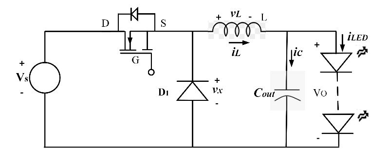 Figure 5: Buck converter
For boost converter in the circuit of Figure 6, during the first interval when the transistor and the diode are switched on and off respectively, the voltage source is supplying the inductor L and the capacitor is providing power to the load formed by a series connection of LEDs. During the second interval when the transistor and the diode are switched off and on respectively, energy is stored in L and in Cout, and provide power to LEDs.
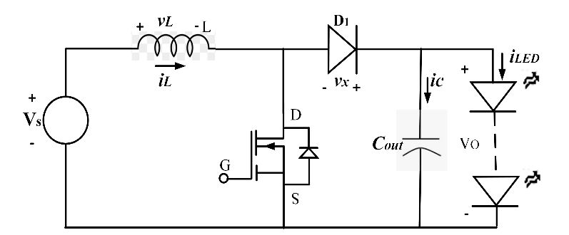 Figure 6: Boost converter
3.2. LED Driver based on Buck converter
A block scheme of a constant-current regulated driver for LED is shown in Figure 7. The output current is set out to a specific value by inserting a resistive current sensor, Rs, in the load branch.
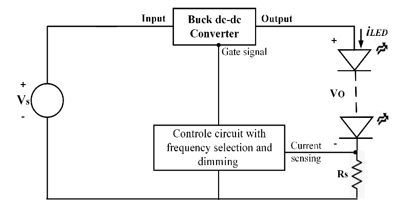 Figure 7: Current controlled LED driver circuit
A block scheme of a constant-voltage boost converter used to drive LED is shown in Figure 8. The output voltage is programmed by placing an appropriate voltage divider, R1-R2, in parallel with the LEDs.
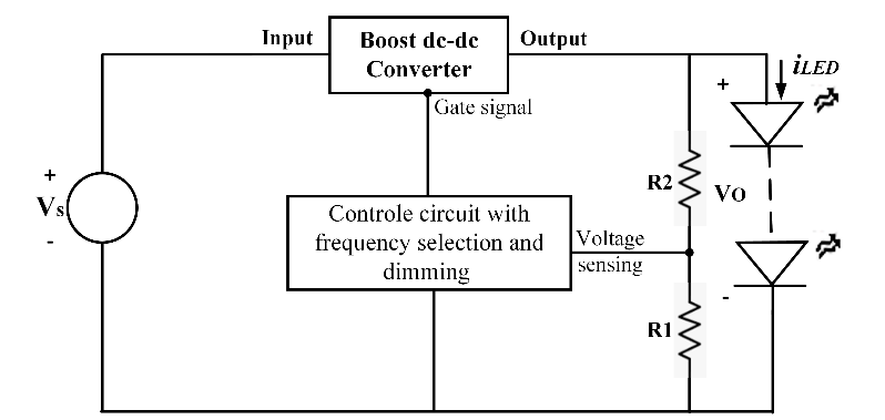 Figure 8: Voltage controlled LED driver circuit
The choice of the switching frequency is a compromise between performance and external component size.
3.3. Constant current versus constant voltage LED driver circuit
LEDs are always driven by a constant current driver. Indeed, based on the LED V-I characteristic in terms of temperature, the forward voltage of LED is decreased when the temperature is increased and vice versa. For a long time, operation of LED under constant voltage, the temperature will raise and consequently the current will raise too which in its turn will cause new increase of temperature. As a result, if the heat created in the LED is not released in an appropriate time, the current will continue raising until the failure of LED. However, in case of constant current source the raise of heat in the LED only results in the drop of forward voltage across it. For applications where the lighting system does specify the voltage, constant voltage driver is used.
4. The design of buck and boost converter
As for any type of converter or driver system, the design aims to satisfy the desired application needs including the load requirements and to determine the system requirements and its parameters.
4.1. Load requirements
The load requirements define the type of light emitting diodes to be used, the rated current, the rated forward voltage, the rated power, the number of LEDs, and the type of connection.
4.2. System requirements and components values
Based on the load requirements, the system requirements is determined by selecting the inductor, the MOSFET, the diode, and the capacitors. The output voltage ripple is reduced by inserting an output ceramic capacitor. Table 1 shows the equations used for calculating the different components [24].
With f: frequency, D: duty cycle, VS: voltage source, VO: output voltage, VDS: Drain Source voltage, Vr: reverse voltage, IF: forward current, IO: output current.
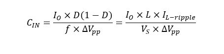
The inductor is selected with a 25% larger current the calculated one in order to avoid its saturation. In addition, the optimal ripple current IL-ripple is 40% of the output current. The input ceramic capacitor is calculated using the following equation
 The requirements for this design are: VS=16V, four 300mA high power LEDs, f=500 kHz, VO-ripple=3%. Based on this, the design parameters required for the converter are:
L=10mH, CIN=2.2mF, Cout =2.2mF, Diode: 1N5819
Table 1: Component selection
| DC-DC buck converter | DC-DC boost converter | |
| Inductor L | ||
| Capacitor Cout | ||
| Diode D1 |
(1-D) |
(1-D) |
| MOSFET |
(1-D) |
5. Simulation and experimental results
5.1. Simulation results
The buck dc-dc- driver circuit of Figure7 is simulated using LTspice. The output voltage VLED, output current ILED, and inductor current IL are shown in Figure. 9, Figure. 10, and Figure. 11. As seen in these figures, the LED current is controlled and it remains constant at 300 mA regardless the variation of the output voltage across the load formed by a series connection of LEDs. By observing the waveform of inductor current it’s clear that its duty cycle is varying according the output voltage variation and its form is a saw-tooth signal as expected.
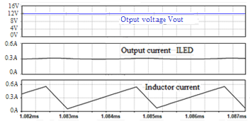 Figure 9: For 4 LEDs: waveforms of VLED, ILED, and IL, f = 500 kHz, and ILED=300 mA
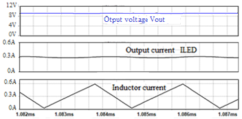 Figure 10: For 3 LEDs: waveforms of VLED, ILED, and IL, f = 500 kHz, and ILED = 300 mA.
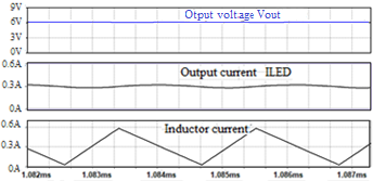 Figure 11: For 2 LEDs: waveforms of VLED, ILED, and IL, f = 500 kHz, and ILED=300 mA.
Table 2 gives numerical values of duty cycle as a response to the change of output voltage for a constant output current as shown in Figures 9 through 11.
Table 2: Duty cycle versus output voltage change for buck converter
| Output voltage (V) | Output current (mA) | Duty cycle |
| 12.6 | 300 | 77.6% |
| 9.4 | 300 | 57.56% |
| 6.2 | 300 | 39.5% |
Regarding dimming capability of the converter, a low frequency pulse width modulation (PWM) signal is used to control the amount of the output current which is closely related to the amount of the emitted light. Simulations conducted for various duty cycles of PWM signal show that the dimming is obtained as illustrated in Figure. 12, Figure. 13, and Figure. 14.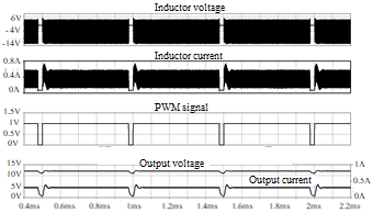 Figure 12: Waveforms of VL, IL, PWM signal, VLED, ILED for dimming level of 95% and ILED–rms =287.2mA.
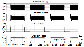 Figure 13: Waveforms of VL, IL, PWM signal, VLED, ILED for dimming level of 70% and ILED, rms =248.22mA
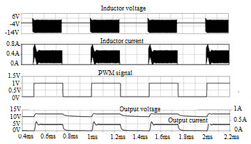 Figure 14: Waveforms of VL, IL, PWM signal, VLED, ILED for dimming level of 50% and ILED, rms =206.69mA
Simulation results for the boost dc-dc- driver circuit of Figure8 show that the voltage across LEDs (VLED) is regulated at 12.8 V regardless the variation of the load current or the input voltage. Figures 15 and 16 depict the output voltage when the load current is changed by connecting in parallel other LEDs. It’s clear that the voltage regulation is achieved by adjusting the duty cycle as a response to the feedback signal issued from the voltage divider connected in parallel with the load.
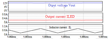 Figure 15: For 4 LEDs: output voltage VLED, output current ILED, and inductor current IL, f = 500 kHz, and VLED = 12.8V
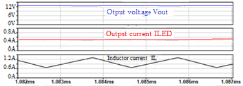 Figure 16: For 8 LEDs (two sets of 4 LEDs connected in parallel): output voltage VLED, output current ILED, and inductor current IL, f = 500 kHz, and VLED = 12.8V
Waveforms displayed in Figure 17, Figure 18, and in Figure 19 show that voltage VLED is also maintained constant when the 6V input voltage is increased or decreased by 1 V in DC-DC boost converter.
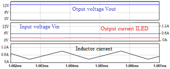 Figure 17: Waveforms of Vout, , ILED, and IL for Vin = 6V, f = 500 kHz, and VLED = 12.8V.
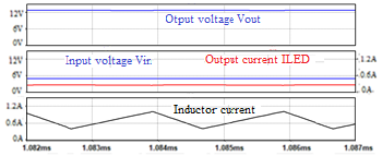 Figure 18: Waveforms of Vout, ILED, and IL for Vin = 7V, f = 500 kHz, and VLED = 12.8V.
Figure 19: Waveforms of Vout, ILED, and IL for Vin = 5V, f = 500 kHz, and VLED = 12.8V.
Table 3 gives numerical values of duty cycle as a response to the change of input voltage for a constant output voltage as shown in Figures 17 through 19.
Table 3: Duty cycle versus input voltage change for boost converter
| Input voltage (V) | Output voltage (mA) | Duty cycle |
| 5 | 12.8 | 60.1% |
| 6 | 12.8 | 54.4% |
| 7 | 12.8 | 43% |
5.2. Experimental results
In previous sections, analysis and design have been performed for buck and boost converter. In this section, experimental results for a prototype of constant-current LED buck converter are presented. The load is formed by four LED light-spot connected in series and mounted on a board as shown in Figure.20 and Figure 21. The reasons for focusing on constant current DC-DC buck converter in experimental study are to ensure that the current doesn’t exceed the rated current, to obtain consistent brightness and color for each LED. In addition, at equal load, the same LC filter has to work much harder in a boost mode compared to buck mode. In the boost case, the capacitor is switching high current and the inductor is carrying high average current. This means that the passive components in the boost converter case must be oversized compared to the buck converter, leading to a higher cost and size. And also means higher ohmic losses and lower efficiency due to the capacitor ESR and inductor ESL. The constant-current LED driver prototype has been built and four LED light-spot have been connected as shown in Figure.20 and Figure 21.
The dimming for LEDs is obtained by application of low frequency pulse width modulation signal with the possibility of duty cycle variation. Various oscilloscope captions are recorded. Figure. 22 depicts the waveform of the output voltage across LEDs when there is no dimming signal.
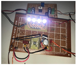 Figure 20: Driver for 4 LED light-spot, f = 500 kHz, and ILED =300 mA.
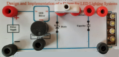
Figure 21: Implementation of the prototype for easy measurements.
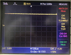 Figure 22: Waveform of VLED for for full duty cycle and ILED = 300 mA
Figure 23 shows the voltage across LEDs and the control signal for pulse width modulation duty cycle set at 0.95
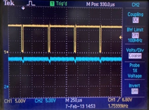 Figure 23: VLED (Bottom) and pulse width modulation signal (Top) with Dcycle = 0.95 and rms current ILED =284mA
Figure 24, shows the voltage cross LEDs and the control signal for duty cycle equal 0.7
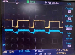 Figure 24: VLED (Bottom) and pulse width modulation signal (Top) with Dcycle = 0.7 and rms current ILED =246mA
Figure 25 shows the voltage cross LEDs and the control signal with pulse width modulation duty cycle set at 0.5.
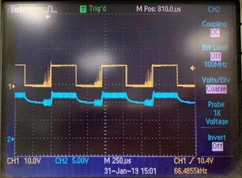 Figure 25: VLED (Bottom) and pulse width modulation signal (Top) with Dcycle = 0.5 and rms current ILED =203mA
Simulation results depicted in Figure. 12, Figure.13, and Figure.14 for 95%, 70%, and 50% dimming levels respectively show good agreement with experimental results conducted under the same conditions of dimming. and presented in Figure. 23, Figure.24, and Figure.25. Indeed, for the three levels of duty cycle 95%, 70%, and 50%, the deviations of LED current in simulation and experimental results are 3.2mA, 2.2mA, and 3.7 mA respectively as shown in Table 2.
Table 2: Dimming of output current: deviation between simulation and experimental result
| Dcycle | 95% | 70% | 50% | |
| ILED, rms
(mA) |
Simulation | 287.2 | 248.2 | 206.7 |
| Experimental | 284 | 246 | 203 | |
| Deviation (mA) | 3.2 | 2.2 | 3.7 | |
6. Conclusion
In this work, design, simulation, implementation, and test of a constant current LED driver with dimming capability have been done. Firstly, during the design stage we started by calculating and selecting the passive components and the semiconductor switches satisfying the system requirements and needs. Then, some simulations and measurements on a prototype of LED driver have been conducted. Comparison of simulation results to those obtained by experiment shows good agreement between them. In addition, regulation of the output current drawn by the LEDs and dimming of the brightness of these LEDs have been achieved. Indeed, the rated output current of the LED is maintained constant at 300 mA regardless the increase or the decrease of the output voltage. Such variation of this voltage is obtained by varying the number of LEDs forming the load. Furthermore, a full dimming is obtained by adjusting the pulse width modulation signal. Each dimming level of the light emitted by LEDs is achieved by controlling their rms current. In addition, a constant voltage LED using boost topology is designed and simulated. The obtained results demonstrated a good driver performance in terms of voltage regulation. This dc-dc boost driver is able to maintain a constant output voltage across the LEDs at 12.8V when the input voltage is adjusted or when the output current is changed by connecting LEDs in parallel.
In both cases, the output voltage is sensed by a voltage divider connected in parallel with the load then applied to a controller to adjust the suitable duty cycle of the signal controlling the power switch.
As a future work, these drivers will be combined in a single buck-boost driver operating as a constant-voltage LED driver (CV) or as a constant-current LED driver (CC) under certain conditions of operation.
Conflict of Interest
The authors declare no conflict of interest.
- H. Yamanaka, H. Yamada, “Dual active bridge DC-DC converter based wide dimming range LED driver with high-speed turn-off for high-brightness LED floodlight,” IEEJ Journal of Industry Applications, 8(3), 556–557, 2019, doi:10.1541/ieejjia.8.556.
- B. Hanna, H. Markus, “Comparison of LED circuits,” OSRAM Opto Semiconductors, 1–10.
- P.S. Almeida, D. Camponogara, M.A.D. Costa, J.M. Alonso, “and Driver Life Spans,” (June 2015), 36–47.
- A.S.O. Ogunjuyigbe, T.R. Ayodele, V.E. Idika, O. Ojo, “Effect of lamp technologies on the power quality of electrical distribution network,” Proceedings – 2017 IEEE PES-IAS PowerAfrica Conference: Harnessing Energy, Information and Communications Technology (ICT) for Affordable Electrification of Africa, PowerAfrica 2017, 159–163, 2017, doi:10.1109/PowerAfrica.2017.7991216.
- Y.K. Cheng, K.W.E. Cheng, “General Study for using LED to replace traditional lighting devices,” 173–177, 2006.
- Y. Jeff, “Solid-state lighting: Lamps, chips, and materials for tomorrow,” IEEE Circuits and Devices Magazine, 20(June), 28–37, 2004, doi:10.1109/MCD.2004.1304539.
- P.A. Meshram, “Investigation and Performance Analysis of Dc-Dc Converter for High Efficiency Led Driver,” 2(12), 444–452, 2016.
- M. Al-Absi, Z. Khalifa, A. Hussein, “A New Capacitor-Less Buck DC-DC Converter for LED Applications,” Active and Passive Electronic Components, 2017, 0–5, 2017, doi:10.1155/2017/2365848.
- LED drivers, LEDs Magazine, (September), 2019.
- R. Xu, H. Li, Y. Li, X. Hou, “Research on a High-Efficiency LED Driving Circuit Based on Buck Topology,” Circuits and Systems, 02(04), 352–357, 2011, doi:10.4236/cs.2011.24048.
- A. Report, “AN-1656 Design Challenges of Switching LED Drivers,” (May), 1–7, 2013.
- S. Rajesh, S.S.C. Bharathi, “A Universal Multistage High Brightness LED Driver for Domestic and Industrial Lighting Application,” 5(4), 107–111, 2014.
- Y. Wang, J.M. Alonso, X. Ruan, “A Review of LED Drivers and Related Technologies,” IEEE Transactions on Industrial Electronics, 64(7), 5754–5765, 2017, doi:10.1109/TIE.2017.2677335.
- T.I. Incorporated, “How to Design a Simple Constant Current/Constant Voltage Buck Converter,” Texas Instruments Incorporated, Application Report, SNVA829, (June), 1–9, 2018.
- D. Agrawal, R.K. Karn, D. Verma, R. Agrawal, “Dc-dc converter topologies for led driver circuit: A review,” International Journal of Circuits, Systems and Signal Processing, 14, 542–547, 2020, doi:10.46300/9106.2020.14.70.
- I.M. Mrabet, “Buck converter Design Supervisor?:”
- H.J. Chiu, Y.K. Lo, J.T. Chen, S.J. Cheng, C.Y. Lin, S.C. Mou, “A high-efficiency dimmable LED driver for low-power lighting applications,” IEEE Transactions on Industrial Electronics, 57(2), 735–743, 2010, doi:10.1109/TIE.2009.2027251.
- M. Nishikawat, Y. Ishizukat, H. Matsuot, K. Shigematsutt, “Circuit with Constant-Output- Current Control and Constant-Luminance Control,” (2), 6–11, 2006.
- P.S. Chavan, M.F.A.R. Satarkar, M.T. Asst, “Overview of control technique for DC-DC Converters,” (May), 51–55, 2015.
- M. Truntic, M. Milanovic, “Voltage and current-mode control for a buck-converter based on measured integral values of voltage and current implemented in FPGA,” IEEE Transactions on Power Electronics, 29(12), 6686–6699, 2014, doi:10.1109/TPEL.2014.2301935.
- U. Nasir, Z. Iqbal, M.T. Rasheed, M.K. Bodla, “Voltage mode controlled buck converter under input voltage variations,” 2015 IEEE 15th International Conference on Environment and Electrical Engineering, EEEIC 2015 – Conference Proceedings, 986–991, 2015, doi:10.1109/EEEIC.2015.7165298.
- J.N. Hemalatha, S.A. Hariprsasad, G.S. Anitha, “Control strategy to generate pwm signals with stability analysis for dual input power converter system,” Indonesian Journal of Electrical Engineering and Informatics, 7(4), 609–619, 2019, doi:10.11591/ijeei.v7i4.976.
- Reshma B R, Arun S Mathew, “Gain Scheduling Implementation in DC/DC Buck Converter using PID Controller,” International Journal of Engineering Research And, V4(07), 1063–1067, 2015, doi:10.17577/ijertv4is070656.
- D.W. Hart, Power elctronics, 2011.
- J. Byun, I. Hong, B. Lee, S. Park, “Intelligent Household LED Lighting System Considering Energy Efficiency and User Satisfaction,” 59(1), 70–76, 2013.
- A. Raciti, S.A. Rizzo, G. Susinni, “Steady-State Electrical Modeling of LED and CF Bulb Lamps Under Variable Voltage on the Main Steady-state electrical modeling of LED and CF bulb lamps under variable voltage on the main,” (June), 2018, doi:10.1109/EEEIC.2018.8494611.
- L. Kukacka, P. Dupuis, R. Simanjuntak, G. Zissis, W. Silver, “Simplified models of LED ballasts for spice,” 1–5, 2014.
- R.V. Monteiro, B.C. Carvalho, G.C. Guimarães, M.A. Tamashiro, “Computational & Math. Modeling of a Buck Driver Type of a Tubular Led Lamp,” IEEE Latin America Trans., 14(5), 2016, doi:10.1109/TLA.2016.7530414.