A Novel Algorithm Design for Locating Fault Distances on HV Transmission Lines

Adv. Sci. Technol. Eng. Syst. J. 7(1), 79–89 (2022);
 DOI: 10.25046/aj070108
The transmission network has been considered among the globe’s prevalent complex systems, comprised of hundreds of electrical transmission lines and other equipment used to transmit electrical energy from one location to another. Over a decade, power engineers have worked tirelessly to ensure that the transmission network operates reliably, transmitting electrical energy from the power station to the consumers without interruption. With growing generation capacity and the recent introduction of renewable energy systems (RES) such as wind turbines and solar energy, the transmission lines are increasingly being forced to run near their design limitations and greater unpredictability on the network operational configuration. As a result, the transmission network faces greater challenges than previously. As a worst-case scenario, large-scale electrical network power outages caused by electrical faults can disrupt electricity availability for several hours, impacting millions of customers and inflicting massive economic damage. These electrical faults must be repaired before electricity is restored to consumers. This necessitates a thorough grasp of the challenge and potential remedies to assure improved power efficiency. In the present work, an expansion of preceding work, a novel algorithm for estimating faults on transmission lines is presented. Impedance-based techniques are susceptible to producing errors or incorrect predictions. The presence of faults induced from high impedance sources produces an extra impedance to the ground, which negates the impedance calculation and produces errors in the distance to the fault. This results in inaccuracies that can affect a distance-to-fault estimation by 1-15 % of the overall line length. In this work, a design of a fault detection-location element (FDLE) algorithm is proposed. This algorithm relies on the dynamics of current and voltage signals on the transmission line while deserting impedance. Comparison research is undertaken against the impedance-based techniques to validate the proposed algorithm. Finally, the proposed algorithm findings are compared to fault location estimations using an impedance-based technique. Extensive trials on a simulated transmission line prove that the proposed algorithm is responsive to faults with an error as low as 1%, reaching a precision of 98.9%.
1. Introduction
This paper is an extension of work originally presented at the 2021 6th Asia Conference on Power and Electrical Engineering (ACPEE) [1]. The transmission network has been considered among the globe’s prevalent complex systems, comprised of hundreds of electrical transmissions such as the addition of wind turbines and solar energy. Therefore, the transmission network faces greater challenges than previously. Over a decade, power designers have worked diligently to guarantee that the transmission network runs adequately, transmitting electrical energy from the power station to customers without disruption. The demand for transmission lines is increasing as the penetration of renewable energy systems (RESs), electric vehicles (EVs), and energy storage systems (ESSs) grows in modern transmission networks [2]. To achieve dependable, efficient, and reliable RESs, significant improvement in the conventional transmission line protection method is necessary. The rapid increase of current during a fault doubles the potential risk of transmission network degradation and thus presents the requirement that faults in RESs be separated by a protection method with the shortest operational time. Due to the increased dependability and stability of RESs, the ring model is the ideal design for RESs because of the bidirectional flow of current in these configurations; the standard protection system would not perform adequately. As a worst-case scenario, large-scale electrical network power outages caused by electrical faults can disrupt electricity availability for several hours, impacting millions of customers and inflicting massive economic damage. These electrical faults must be repaired before electricity is restored to consumers. The introduction of the proposed algorithm may aid in the improvement of these systems.
Many electric utilities have opted to invest minimal, or no effort in electrical transmission fault detection devices in the past, alleging that faults are usually temporary thus do not necessitate location. Moreover, [3] suggested that the data produced by protection relays were not accurate enough to support deploying personnel to check temporary fault locations. As a result, fault location operations were commenced immediately after a fault had become permanent and a solution was required. With the restructuring and privatisation of electric power production enterprises across the globe, such sentiments are beginning to change [4, 5]. To attain the greater plant efficiency levels and increased service reliability regulations that a dynamic industry needs, electricity utilities are increasingly taking a more “pro-active” strategy to most business operations, notably in the field of transmission line fault location. The capability of impedance-based techniques to address the errors and constraints of protection relays was discovered in the mid-20th century when various trial designs were introduced; several of them were converted into industrial uses [6]. Although such designs are more accurate than other methods, they were discontinued due to dependability and maintenance issues, leading to a lack of involvement and credibility. Impedance-based fault location techniques are used repeatedly on transmission lines [7]. Many causes drive the resurgence of impedance-based techniques, the foremost of which is an industry need for quick and precise fault location on economically vital, extremely lengthy high-voltage transmission lines. Precise fault location lowers operational expenses by eliminating costly and time-consuming inspections [8]. Precise fault location speeds up line maintenance and recovery, decreasing revenue shortfall due to outages. Comparison research is undertaken against other techniques to validate the proposed algorithm.
In [9], the authors proposed an artificial intelligence-based approach for detecting faults in photovoltaic (PV) plants and transmission lines. The method is known as recurrent neural networks (RNN). The authors stress that faults in PV plants are usually foreseeable, and while conventional methods are precise, they are not cost-effective for mass application, allowing most PV plants to operate unmonitored. They developed an algorithm for precise fault diagnosis of PV plants that uses satellite weather data and low-frequency inverter sensors. The algorithm enables machine learning-based fault detection even for PV plants with the absence of detectors, and it utilises a recurrent neural network to detect all forms of defects based on the last 24 hours of observations, rather than just the latest detected fault. The authors also demonstrated that the proposed algorithm determines the generated power loss induced by the fault, for example, the fault level, whereas the traditionally utilised techniques are restricted to classifying the fault type. The results show that the algorithm is responsive to as low as 5 % intensity defects, with a precision of 96.9% utilising accurate climate data and 86.4% utilising satellite weather data. The results reveal that the algorithm could also detect unspecified defects, that is, defects that appeared to be not included in the training data.
The authors in [10] presented a closed-loop sinusoidal pulse width modulation (SPWM) monitoring device for the operations of converters utilised in wind turbine plants for utility grid purposes. Wind energy is a major form of clean energy; therefore, windmills are commonly deployed in electrical distribution systems and thus are coupled physically to electrical transmission systems. Wind energy significantly influences the performance of current configuration systems as network saturation improves, resulting in the probability of faults on the transmission lines transporting power to the main grid. The presented technique is utilised to investigate wind turbine efficiency. The authors state that voltage and current inverters produce discrete output waveform signals, harmonic pollution, extra power losses, and higher frequency noises. As a result, to achieve the required current waveforms, large inductors must be connected in line with the related load. The simulated results showed that the mentioned technique has a higher harmonic elimination strength. As a result, the transmission network will require fewer fault detecting and locating devices.
In [11], the authors presented a technique for performing serial fault repair in a wind turbine plant with synchronous actuator and sensor defects. The technique is known as a robust sliding mode observer (SMO). The authors used a diagonal transform matrix and a post-filtering system to design a novel improved model. The novel model then transforms the sensor fault into an actuator fault to locate the fault. The novel model allows the SMO technique to detect and pinpoint faults on transmission lines. The simulated tests indicate how the presented technique can properly restore actuator and sensor defects; thus, the active fault controller can obtain optimum wind power extraction. Although this technique works optimally for a microgrid that operates in an islanded mode, there is no concise evidence of how this technique functions when employed to a transmission line of a microgrid configuration integrated into the main grid.
The theories of the single and double-ended impedance-based fault location techniques are also discussed in this paper and explain the concepts related to fault location and present different impedance-based fault location algorithms. The work aims to investigate numerous network faults and assess the efficiency of fault locators in light of potential causes of inaccuracy [12].
In the present work, an expansion of preceding work [1], a novel algorithm for estimating faults on transmission networks is presented. Impedance-based techniques are susceptible to producing errors or incorrect predictions. The presence of faults induced from high impedance sources produces an extra impedance to the ground, which negates the impedance calculation and produces errors in the distance to the fault. This results in inaccuracies that can affect a distance-to-fault estimation by 1 -15 % of the overall line length. This will have a detrimental impact on the transmission network and renewable energy systems. In this work, a design of a fault detection-location element (FDLE) algorithm is proposed. The model utilises MATLAB/SIMULINK software to study the electrical faults on a transmission line. The proposed algorithm relies on the dynamics of current and voltage signals on the transmission line while deserting impedance. The authors provide simulation results to demonstrate the efficiency of the proposed algorithm. The FDLE algorithm findings are compared to fault location estimations using an impedance-based approach. Extensive trials on a simulated transmission line prove that the proposed algorithm is responsive to faults with an error as low as 1%, reaching a precision of 98.9%.
2. Techniques and Specifications for Fault Diagnosis
Various techniques of predicting fault position are currently in practice in the industry [13]:
- Conventional methods:
- Impedance-based methods [14]:
- Single-ended method, and
- Double-ended method (Synchronized, Unsynchronized, and Unsynchronized Current-only).
- Travelling wave methods [15, 16]:
- Single-ended method, and
- Double-ended method.
- Artificial Intelligence methods:
- Artificial Neural Network (ANN) [17],
- Support Vector Machine (SVM) [18],
- Fuzzy Logic [19], and
- Matching Approach [20].
In this work, comparison research is undertaken against the impedance-based techniques to validate the proposed algorithm and presents the outcomes using real-world simulated faults.
3. Theoretical Foundations of Impedance-based Fault Location Techniques
Various impedance-based fault location techniques have been designed for transmission lines purposes. Single-ended techniques are fault-locating techniques that use information recorded by a fault location detection element at one end-point of the transmission line to locate faults [21]. Double-ended techniques use information from fault location detection elements at both end-points of the connection. The impedance between both the fault locator and the position of the fault is estimated using voltage and current signals collected by fault location detection elements during a fault [22]. The distance to the fault may be precisely determined if the transmission line impedance in ohms is known. When determining the proximity to a fault, each technique has different basic data needs and requires different estimates. These estimates may or may not be valid in a specific fault position case [23]. Selecting the appropriate technique for pinpointing faults within quite a diverse set of impedance-based fault location techniques is thus a challenging effort that demands a diligent grasp of the essential principles of an individual fault-locating technique. Constructed on the preceding knowledge, this paper discusses the fundamental concept of single-ended and double-ended impedance-based fault location techniques. The aims are to properly articulate each fault-finding technique’s input data requirements, explain each technique’s applicability in pinpointing actual transmission line faults, and offer advice on selecting the optimal fault-locating technique.
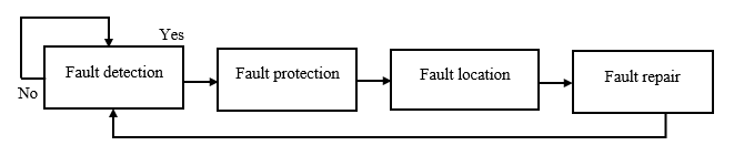 Figure 1: Flow Chart Procedure of a Conventional Technique.
4. Techniques and Prerequisites for Impedance-based Fault Location
The underlying analysis is required for impedance-based techniques:
- Voltage and current amplitudes should be recorded,
- Extract the essential elements,
- Identify the fault category and faulted phasor/s, and
- Employ the impedance-based technique.
Single-ended impedance techniques employ a simplified approach. Hence, links between communicating and off-site data are typically unnecessary [24]. Whereas double-ended techniques are extremely precise. However, they require data from both end-points of the transmission line. For this technique to be executed [25].
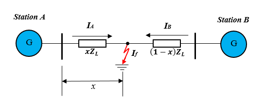 Figure 2: A Single-ended Impedance-based Algorithm.
Table 1: Different Formulae for Fault Types [1].
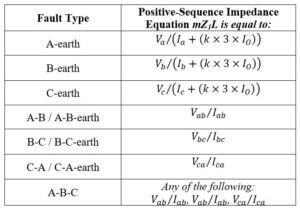
The single-ended impedance-based fault location technique determines the fault position using the detected impedance through examining the transmission line from a single end-point. Every line’s line-to-line and line-to-ground output signal must be recorded to pinpoint all fault forms [12]. The impedance equations shown in Table 1 may be utilised to approximate the fault position assuming zero fault resistance.
Where VA, VB, and VC are the phase voltages,
IA, IB, and IC are the phase currents,
ZO the zero-sequence impedance,
Z1 the positive sequence impedance, and
KO the residual compensation factor and may be expressed as:
 K may be 1 or 3, depending on the fault location detection element design. According to Kirchhoff’s law, the zero-sequence Io in Equation (2) will be zero in a balanced system.

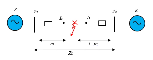
Figure 3: A Double-ended Impedance-based Algorithm.
Where m in Figure 3 denotes the distances to a fault per unit [26], the sending voltage, the receiving voltage, the sending current, the receiving current, and the impedance of the line.
The difficulties in accurately locating faults using single-ended techniques are recognised and documented in numerous publications [27].
To summarise, the preceding circumstances may result in single-ended impedance-based fault location techniques producing errors:
- Imprecise fault-type (faulted phase/s) detection.
- Incorrect line parameters that do not correspond to actual parameters.
- Lack of accuracy of the line model.
- Current and voltage transformer errors.
5. Single-ended Impedance-based Method
5.1. Simple Reactance Technique
The potential difference loss at the sending (S) end of the transmission line, illustrated in Figure 4 is:
![]()
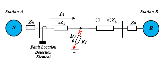 Figure 4: Faulted Transmission Network with Fault Location Detection Element.
For an A phase to earth fault, it must have the following characteristics,
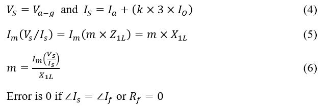 The objective is to reduce the impact of the variable. The basic reactance algorithm divides all variables by (I obtained at the fault location) and excludes the variable .
To achieve this, preserve the imaginary component and solve m.
5.2. Takagi Technique
The Takagi technique needs the collection of pre-fault and fault data. It mostly enhances the simple reactance technique by minimising the influence of fault resistance and lowering the impact of load flow [28].
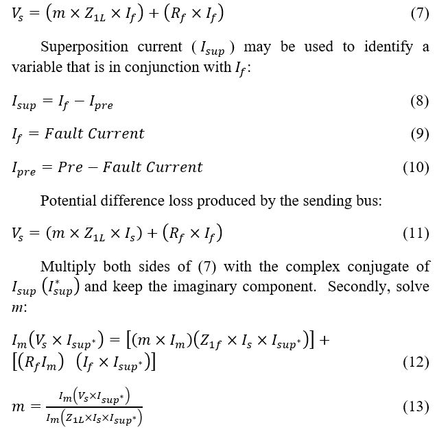
The fact that and angles are the equivalents that are important to the Takagi technique’s efficiency. These angles are the same in a perfect homogenous network. The inaccuracy in the fault position estimation improves as the angle between and improves [29].
5.3. Modified Takagi Technique
For earth faults, the modified Takagi utilises zero-sequence current from the sending end rather than the superposition current. As a result, no pre-fault data is required for this technique. Angle rectification is similarly possible with the Modified Takagi technique. Provided that the user understands the network source impedances, he/she can change the zero-sequence current using angle T to enhance the fault position estimation for a specific transmission line [30].
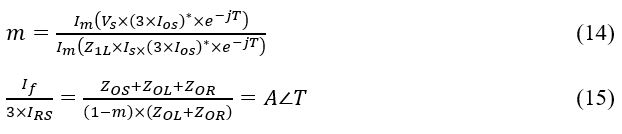
The defined angle T is only applicable for a single fault point within the transmission line. Figure 5 demonstrates methods to compute T.
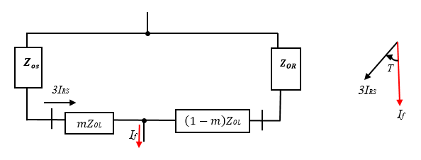 Figure 5: Correction of a Zero Sequence Angle.
Even though the Modified Takagi technique outperforms the Takagi technique, the precision of position estimations is dependent on having the source impedance characteristics precisely.
5.4. Eriksson Technique
This technique employs the generated impedance characteristics to avoid any reactance inaccuracy induced from fault resistance, loads, or non-homogeneity network to determine the distances to the fault. Furthermore, such a technique evaluates the magnitude of fault impedance, which is important in detecting the main reason for a fault and verifying a transmission network short-circuit design [31].
Equation (16) summarises and updates the variables in Equation (14).
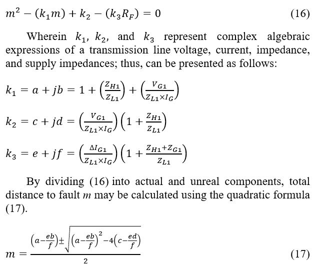
Should m be known, any other unknown variable may be obtained using Equation (17). Given that the fault position prediction has to be smaller than the entire transmission line distance, an m value of between 0 and 1 per unit must be utilised for the distance measurement.
Therefore, Equation (18) may be used to determine fault tolerance:

Assuming that the supply impedance is not known, and the load impedance is precisely calculated, the impedance can be estimated using fault occurrence records as:
5.5. Novosel et al. Technique
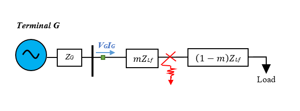 Figure 6: Novosel et al. Technique Applied to a Transmission Network with a Constant Impedance Load.
The Novosel et al. technique is a revised edition of the Eriksson technique for pinpointing faults on a compact, radial transmission line. At downstream of the transmission line, all the loads supplied or connected to the line are combined. Given that there is a fixed load impedance design, the initial action is to determine the load impedance using the pre-fault current and voltage as inputs [14]; this is expressed as:
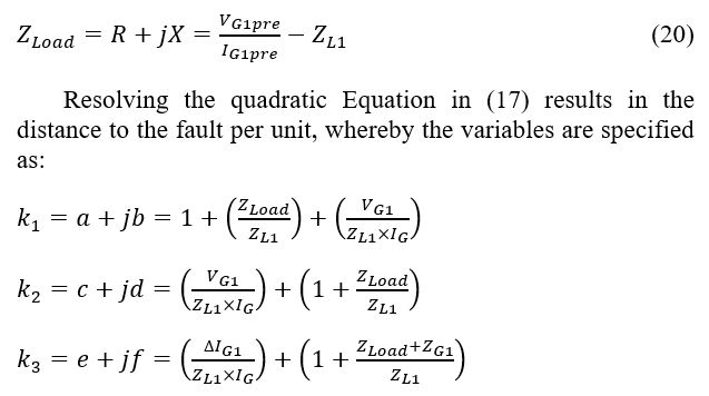
Similar to the Eriksson technique, m can include any of these variables on the Novosel et al. technique. Given that the fault position prediction must be less than the total transmission line distance, several m between 0 and 1 per unit must be used for distance measurement.
6. Double-ended Impedance-based Method
6.1. Synchronised Two-ended Technique
This technique is built on the hypothesis that data from both end-points of a transmission line are coordinated to a similar period response using a global positioning system (GPS). During fault position analysis, any three symmetric variables can be employed. However, utilising negative-sequence elements is highly beneficial because it is unaffected by load current or zero-sequence connected loads feeding to the system. To demonstrate the fault-finding concept, a negative-sequence system amid an imbalanced fault must be considered [32].
Figure 7 illustrates how to compute VF2, the negative-sequence potential difference at the fault location F, using Terminals G and H. The Equations are represented as:
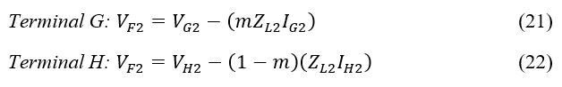
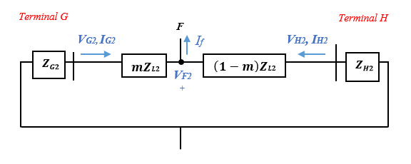 Figure 7: Negative Sequence System during Asymmetrical Fault.
The potential difference VF2 determined on either bus of the transmission line is equivalent. As a result of matching Equations (21) and (22), the distance measurement to a fault is calculated as:
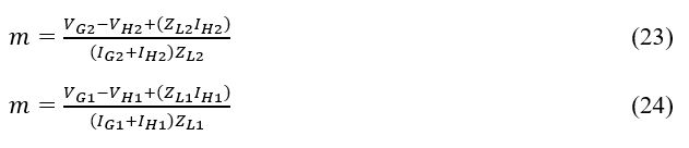 A symmetrical fault may be located using Equation (23). On the other hand, negative-sequence components do not occur when a symmetrical fault is present. In this scenario, the identical fault pinpointing approach is used for the positive sequence system, and the fault distance is calculated as in (24).
6.2. Unsynchronised Two-ended Technique
In this technique, current and voltage signals recorded by fault location detection elements at opposite ends of a transmission line could be out of synchronisation. The GPS sensor could be damaged or barely working properly. Fault location detection elements can also have various sample speeds or pinpoint the fault at marginally varying time intervals [33].
A phase shift can be caused by the communication route that transmits data from one fault location detection element to the other. As a result, must be employed as a synchronising controller to synchronise the voltages and currents measured at Terminals G and H. This process is as follows:

When the algebraic expression in (28) is solved, two parameters of m are obtained. The fault position estimation must have a value of 0 to 1 per unit.
6.3. Unsynchronised Current-only Two-ended Technique
This technique is used when there are data accessibility constraints, assuming that merely current signals at buses G and H are provided for fault analysis and the voltage signals and are either absent or unavailable. is determined from the two buses using just the current as well as the supply impedance characteristics as:

This technique is only convenient for pinpointing imbalanced faults. Given that current data is available, the position predictions’ precision depends on having the supply impedance characteristics precisely [34].
7. Proposed Model
The proposed model is shown in Figure 8. The model is applied to a simulated transmission line design. The sequencing plan of the algorithm utilised to pinpoint the transmission line faults is indicated in Figure 9.
 Figure 8: Proposed Algorithm Model.
Measurements will be obtained, parameters will be computed to construct an appropriate transmission line model utilising MATLAB/SIMULINK software, and several adjustments will be required to achieve a robust and efficient network.
The second process is implementing multiple faults on a selected line at various intervals from a designated end terminal. The pre-fault, fault, and post-fault voltage and current waveforms will be studied. These data can then be utilised to determine the location of the fault. Assuming that all the phases are completed successfully, the precise current and voltage signals are gathered and used to pinpoint the exact position of the fault, as illustrated in Figure 9.
 Figure 9: Proposed Algorithm Flow Chart.
The MATLAB/SIMULINK Model is presented in figure 10.
 Figure 10: Transmission Line Design with a Single-ended Impedance-based Fault Location Technique.
8. Simulation Results
The Simulation results are as fellows
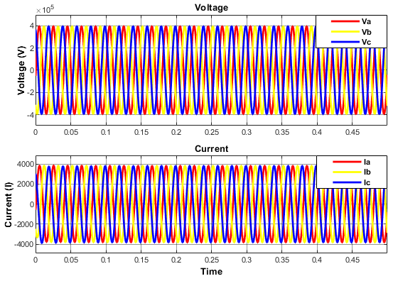 Figure 11: Balanced Voltage & Current Waveforms.
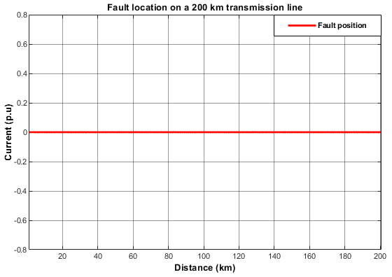 Figure 12: No Located Fault/s.
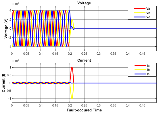 Figure 13: Distorted Voltage & Current Oscillations Induced by L-L Fault.
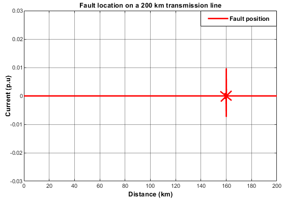 Figure 14: L-L Fault Pin-pointed at 160.5 km.
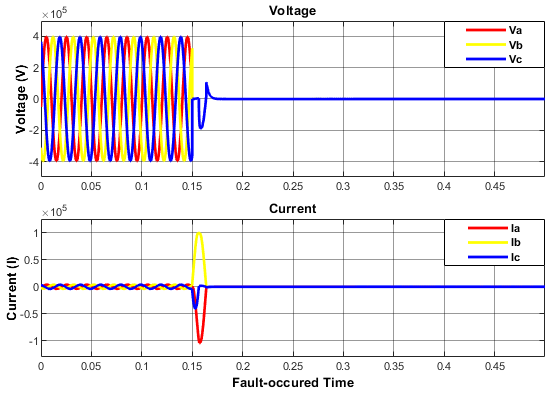 Figure 15: Distorted Voltage & Current Oscillations Induced by L-L-L Fault.
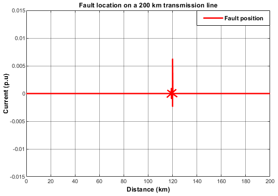 Figure 16: L-L-L Fault Pin-pointed at 119.7 km.
 Figure 17: Distorted Voltage & Current Oscillations Induced by L-G Fault.
 Figure 18: L-G Fault Pin-pointed at 79.9 km.
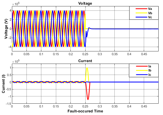 Figure 19: Distorted Voltage & Current Oscillations Induced by L-L-G Fault.
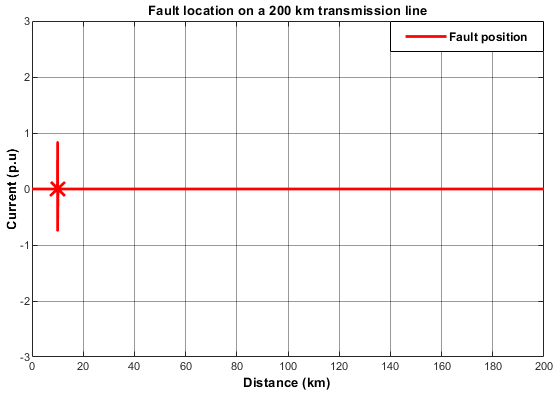 Figure 20: L-L-G Fault Pin-pointed at 10.6 km.
 Figure 21: Distorted Voltage & Current Oscillations Induced by L-L-L-G Fault.
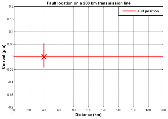 Figure 22: L-L-L-G Fault Pin-pointed at 41 km.
 Figure 23: Distorted Voltage & Current Oscillations Induced by L-G Fault.
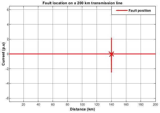 Figure 24: L-G Fault Pin-pointed at 140.9 km.
 Figure 25: Distorted Voltage & Current Oscillations Induced by L-L Fault.
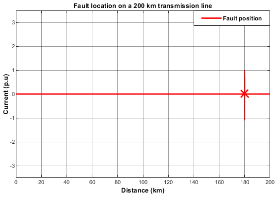 Figure 26: L-L Fault Pin-pointed at 179.2 km.
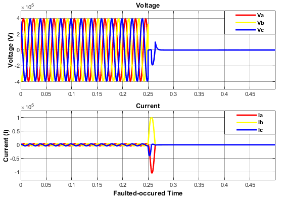 Figure 27: Distorted Voltage & Current Oscillations Induced by L-L-L Fault.
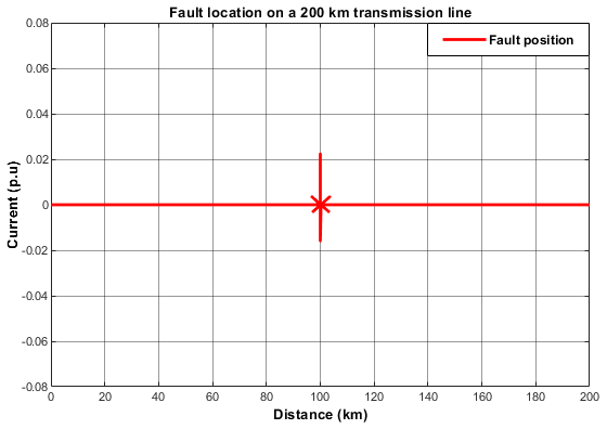 Figure 28: L-L-L Fault Pin-pointed at 98.9 km.
9. Practical Results
In this section, the calculated fault distances using the impedance-based technique are presented in Table 2. The results were obtained from test fault cases involving different faults on a 200 km transmission line. The accuracy of the fault distances was calculated using Equation (32).
(32)
Table 2: Error of Estimation: Impedance-based Technique.
| Length of the Line (km) | Fault Type | Distance of the Fault (km) | Calculated Fault Distance (km) | Error (%) |
| 200 | L-G | 80 | 78.7 | 1.65 |
| 200 | L-L | 160 | 146.8 | 6.6 |
| 200 | L-L-G | 10 | 6.4 | 1.8 |
| 200 | L-L-L | 120 | 115.2 | 2.4 |
| 200 | L-L-L-G | 40 | 32.1 | 3.95 |
| 200 | L-L | 180 | 176.5 | 1.75 |
| 200 | L-G | 140 | 136.7 | 1.65 |
| 200 | L-L-L | 100 | 106.4 | -3.2 |
It is observed that the impedance-based technique achieves accurate estimations that are within 1-15% of the designed transmission line.
10. Results Comparison
This section presents the percentage error of the simulated results utilising the proposed algorithm against the calculated results of the impedance-based technique for the designed transmission line. Table 3 illustrates that the proposed algorithm provides a more accurate fault location than the impedance-based technique in all scenarios.
It is shown in Table 3 that the proposed algorithm gives precise predictions with an approximation of less than 1% from the simulated transmission line. As an outcome, it is evident that the proposed algorithm provides more precision.
Table 3: Error of Estimation: Impedance-based Technique against the Proposed Algorithm.
| Length of the Line (km) | Fault Type | Distance of the Fault (km) | Calculated Fault Distance (km) | Error
(%) |
| 200 | L-G | 80 | 1.65% | 0.05% |
| 200 | L-L | 160 | 6.6% | -0.25% |
| 200 | L-L-G | 10 | 1.8% | -0.3% |
| 200 | L-L-L | 120 | 2.4% | 0.15% |
| 200 | L-L-L-G | 40 | 3.95% | -0.5% |
| 200 | L-L | 180 | 1.75% | 0.4% |
| 200 | L-G | 140 | 1.65% | -0.45% |
| 200 | L-L-L | 100 | -3.2% | 0.55% |
11. Conclusion
This work presents the results of an impedance-based technique to the results of the proposed algorithm on a 200-km transmission line. It was observed that the impedance-based techniques are susceptible to producing errors or incorrect predictions. The presence of faults induced from high impedance sources produces an extra impedance to the ground, which negates the impedance calculation and produces errors in the distance to the fault. This results in inaccuracies that can affect a distance-to-fault estimation by 1-15 % of the overall length. Comparison research was undertaken against the impedance-based techniques to validate the proposed algorithm. The simple reactance technique is considered to be the most basic technique. However, the precision of such a technique suffers in a non-homogenous network due to fault resistance, load current, and distant infeed. The Takagi technique, for instance, is load resistant; however, insensitive to distant infeed. For most scenarios, double-ended impedance-based fault location techniques achieve better outcomes. Studying the fault location usage situation can help determine what extra devices are required to improve the performance of fault-location techniques.
In the present work, an expansion of preceding work [1] introduced a novel algorithm for estimating faults on transmission lines. Extensive trials on a simulated transmission line led to the conclusion of this work. It was observed that the impedance-based technique achieves accurate estimations within 1-15% of the designed transmission line, and the proposed algorithm gives precise predictions with an approximation of less than 1% from the simulated transmission line, reaching a precision of 98.9%. As an outcome, it was evident that the proposed algorithm provides more precision.
In future work, the authors will test the proposed algorithm on a distributed system due to the availability of multiple incomers and feeders connected to the system. Furthermore, the authors will perform a study by simultaneously integrating the proposed algorithm and an artificial neural network (ANN) technique on a complex transmission line and comparing the two algorithms’ accuracy.
Conflict of Interest
The authors declare no conflict of interest.
Acknowledgement
The author wishes to convey his gratitude to the university for offering him the possibility to work with such a stellar supervisor as Dr. PF Le Roux and offer impactful commentary.
- M.K Ngwenyama, P.F Le Roux, L.J. Ngoma, “Conventional Method for Electrical Transmission System Fault Location Detection,” in 2021 6th Asia Conference on Power and Electrical Engineering (ACPEE), 69-76, 2021, doi: 10.1109/ACPEE51499.2021.9437010.
- S.M. Hakimi, A. Hasankhani, M. Shafie-khah, M. Lotfi, J.P. Catalão, “Optimal sizing of renewable energy systems in a Microgrid considering electricity market interaction and reliability analysis,” Electric Power Systems Research, 107678, 2022, doi: 10.1016/j.epsr.2021.107678.
- P. Bunnoon, “Fault detection approaches to power system: state-of-the-art article reviews for searching a new approach in the future,” International Journal of Electrical and Computer Engineering, 553, 2013.
- S.A. Aleem, N. Shahid, I.H. Naqvi, “Methodologies in power systems fault detection and diagnosis,” Energy Systems, 85-108, 2015, doi: 10.1007/s12667-014-0129-1.
- S.S. Gururajapathy, H. Mokhlis, H.A. Illias, “Fault location and detection techniques in power distribution systems with distributed generation: A review,” Renewable and sustainable energy reviews, 949-958, 2017.
- A. Keshavarz, R. Dashti, M. Deljoo, H.R. Shaker, “Fault location in distribution networks based on SVM and impedance-based method using online databank generation,” Neural Computing and Applications, 1-17, 2021.
- J. Wang, Y. Zhang, T. Li, “Equivalent characteristic impedance based hybrid-HVDC transmission line fault location,” Electric Power Systems Research, 107055, 2021, doi: 10.1016/j.epsr.2021.107055.
- X. Tong, H. Wen, “A novel transmission line fault detection algorithm based on pilot impedance,” Electric Power Systems Research, 106062, 2020, doi: 10.1016/j.epsr.2019.106062.
- J. Van Gompel, D. Spina, C. Develder, “Satellite based fault diagnosis of photovoltaic systems using recurrent neural networks,” Applied Energy, 117874, 2022, doi: 10.1016/j.apenergy.2021.117874.
- A.H. Hassanabad, D. Nazeipur, “Design and Simulation of a Control System for Investors in Wind Turbines.”
- X. Wang, Y. Shen, “Fault-tolerant control strategy of a wind energy conversion system considering multiple fault reconstruction,” Applied Sciences, 794, 2018.
- M. Nemati, M. Bigdeli, A. Ghorbani, “Impedance-based fault location algorithm for double-circuit transmission lines using single-end data,” Journal of Control, Automation and Electrical Systems, 1267-1277, 2020, doi: 10.1007/s40313-020-00620-w.
- J. Doria-Garcia, C. Orozco-Henao, L. Iurinic, J.D. Pulgarín-Rivera, “High impedance fault location: Generalized extension for ground faults,” International Journal of Electrical Power & Energy Systems, 105387, 2020, doi: 10.1016/j.ijepes.2019.105387.
- L. De Andrade, T.P. de Leão, “Impedance-based fault location analysis for transmission lines,” in PES T&D 2012, 1-6, 2012, doi: 10.1109/TDC.2012.6281527.
- D.W. Thomas, C. Christopoulos, R.J.d.O. Carvalho, E.T. Pereira, “Single and double ended travelling-wave fault location on a MV system,” 2004, doi: 10.1049/cp_20040098.
- M. Ngwenyama, P. Le Roux, L. Ngoma, “Traveling Wave fault location detection technique for high voltage transmission lines,” in 2021 2nd International Conference for Emerging Technology (INCET), 1-7, 2021, doi: 10.1109/INCET51464.2021.9456334.
- M.T. Hagh, K. Razi, H. Taghizadeh, “Fault classification and location of power transmission lines using artificial neural network,” in 2007 International Power Engineering Conference (IPEC 2007), 1109-1114, 2007.
- S. Ekici, “Support Vector Machines for classification and locating faults on transmission lines,” Applied soft computing, 1650-1658, 2012, doi: 10.1016/j.asoc.2012.02.011.
- A. Prasad, J.B. Edward, C.S. Roy, G. Divyansh, A. Kumar, “Classification of faults in power transmission lines using fuzzy-logic technique,” Indian Journal of Science and Technology, 1-6, 2015, doi: 10.17485/ijst/2015/v8i30/77065.
- L. Wei, W. Guo, F. Wen, G. Ledwich, Z. Liao, J. Xin, “Waveform matching approach for fault diagnosis of a high-voltage transmission line employing harmony search algorithm,” IET generation, transmission & distribution, 801-809, 2010, doi: 10.1049/iet-gtd.2010.0104.
- L. Ji, X. Tao, Y. Fu, Y. Fu, Y. Mi, Z. Li, “A new single ended fault location method for transmission line based on positive sequence superimposed network during auto-reclosing,” IEEE Transactions on Power Delivery, 1019-1029, 2019, doi: 10.1109/TPWRD.2019.2901835.
- A. Di Tomasso, G. Invernizzi, G. Vielmini, “Accurate single-end and double-end fault location by traveling waves: a review with some real applications,” in 2019 AEIT International Annual Conference (AEIT), 1-6, 2019.
- F. Aboshady, D. Thomas, M. Sumner, “A new single end wideband impedance based fault location scheme for distribution systems,” Electric Power Systems Research, 263-270, 2019, doi: 10.1016/j.epsr.2019.04.034.
- J. Barati, A. Doroudi, “Novel modified impedance-based methods for fault location in the presence of a fault current limiter,” Turkish Journal of Electrical Engineering & Computer Sciences, 1881-1893, 2018, doi: 10.3906/elk-1711-127.
- F. Wang, X. Feng, L. Zhang, Y. Du, J. Su, “Impedance‐based analysis of grid harmonic interactions between aggregated flyback micro‐inverters and the grid,” IET Power Electronics, 453-459, 2018, doi: 10.1049/iet-pel.2017.0356.
- A. Abu-Siada, M.I. Mosaad, S. Mir, “Voltage–current technique to identify fault location within long transmission lines,” IET Generation, Transmission & Distribution, 5588-5596, 2020, doi: 10.1049/iet-gtd.2020.1012.
- K. Morgan, W. Gamal, K. Samuel, S.D. Morley, P.C. Hayes, P. Bagnaninchi, J.N. Plevris, “Application of impedance-based techniques in hepatology research,” Journal of clinical medicine, 50, 2020, doi: 10.3390/jcm9010050.
- D. Guillen, C. Salas, L. Fernando Sanchez‐Gomez, L.M. Castro, “Enhancement of dynamic phasor estimation‐based fault location algorithms for AC transmission lines,” IET Generation, Transmission & Distribution, 1091-1103, 2020, doi: 10.1049/iet-gtd.2019.0051.
- C. Zhang, Y. Yu, Y. Wang, M. Zhou, “Takagi–Sugeno fuzzy neural network hysteresis modeling for magnetic shape memory alloy actuator based on modified bacteria foraging algorithm,” International Journal of Fuzzy Systems, 1314-1329, 2020, doi: 10.1007/s40815-020-00826-9.
- A. Macioł, P. Macioł, B. Mrzygłód, “Prediction of forging dies wear with the modified Takagi–Sugeno fuzzy identification method,” Materials and Manufacturing Processes, 700-713, 2020, doi: 10.1080/10426914.2020.1747627.
- S. Roostaee, M.S. Thomas, S. Mehfuz, “Experimental studies on impedance based fault location for long transmission lines,” Protection and Control of Modern Power Systems, 1-9, 2017.
- M.N. Hashim, M.K. Osman, M.N. Ibrahim, A.F. Abidin, “Investigation of features extraction condition for impedance-based fault location in transmission lines,” in 2017 7th IEEE International Conference on Control System, Computing and Engineering (ICCSCE), 325-330, 2017, doi: 10.1109/ICCSCE.2017.8284428
- A. Dalcastagne, S. Zimath, “A study about the sources of error of impedance-based fault location methods,” in 2008 IEEE/PES transmission and distribution conference and exposition: Latin America, 1-6, 2008, doi: 10.1109/TDC-LA.2008.4641697
- K. Ramar, H. Low, E.E. Ngu, “One-end impedance based fault location in double-circuit transmission lines with different configurations,” International Journal of Electrical Power & Energy Systems, 1159-1165, 2015, doi: 10.1016/j.ijepes.2014.09.006.